


Samlex America SK User Manual

SK Series
Pure Sine Wave Inverter
User’s Manual

Table of Contents
1. Important Safety Information.……………………………………………… 1
1-1 General Safety Precautions…………………………………………… 1
1-2 Battery Precautions………………………..………………………….. 1
2. Features………………………………………………………………………... 2
2-1 Application………………………………………………………………. 2
2-2 Electrical Performance………………………………………………… 3~7
2-3 Mechanical Drawings………………………………………………….. 8~9
3. Introduction…………………………………………………………………… 10
3-1 Front Panel operation….……………………………………………... 10~13
3-2 Rear Panel operation.………………………………………………… 14~15
3-3 Protections Features…………………………………………………… 15
3-4 Installation………………………………………………………………. 16
3-5 Making DC Wiring Connections ……………………………………... 17~19
3-6 AC Safety Grounding………………………………………………….. 20
3-7 Inverter Operation……………………………………………………… 21
4. Troubleshooting guide……………………………………………………… 22
5. Maintenance…………………………………………………………………… 23
6. Warranty……………………………………………………………………….. 23
1. Important Safety Instructions
WARNING!
Before using the Inverter, read and save the safety
instructions.
1-1. General Safety Precautions
1-1-1. Do not expose the Inverter to rain, snow, spray, bilge or dust.
To reduce risk of hazard, do not cover or obstruct the ventilation
openings. Do not install the Inverter in a zero-clearance compartment.
Overheating may result.
1-1-2. To avoid a risk of fire and electronic shock, make sure that existing
wiring is in good electrical condition and not undersized.
Do not operate the Inverter with damaged or substandard Wiring.
1-1-3. There are some components in the inverter can cause arcs and sparks.
To prevent from fire or explosion, do not put batteries, flammable
materials, or anything should be ignition–protected around the inverter.
1-2. Precautions When Working with Batteries
1-2-1. If battery acid contacts skin or clothing, you shall wash it out with soap
and water immediately. If battery acid contacts your eyes, you shall
wash it out with cold running water for at least 20 minutes and get
medical attention i
1-2-2.
1-2-3. Do not drop a metal tool on the battery. The resulting spark or
1-2-4. Remove personal metal items such as rings, bracelets, necklaces,
Never smoke or make a spark or flame in the vicinity of the battery or
the engine.
short-circuit on the battery of other electrical part may cause an
explosion.
and watches when operating with a lead-acid batteries.
mmediately.
Doing so may cause short circuit and very high temperature, which can
melt metal items and even burn you.
1

2. Features
Pure sine wave output (THD < 3%)
Output frequency:50 / 60Hz switch selections
Input & output fully isolated design
Power Saving Mode to conserve energy
High efficiency 89~94%
Driving highly reactive & capacitive loads at start moment
Tri-Color indicators show input voltage & output load level
Loading controlled cooling fan
Advanced microprocessor
Protection:Input low voltage Overload Short circuit
Low battery alarm Input over voltage Over temperature
2-1. Application
2-1-1. Power tools – circular saws, drills, grinders, sanders, buffers, weed
and hedge trimmers, air compressors, etc.
2-1-2. Office equipment – computers, printers, monitors, facsimile machines,
scanner, etc.
2-1-3. Household appliances – vacuum cleaners, fans, fluorescent and
incandescent lights, shavers, sewing machines.
2-1-4. Kitchen appliances – coffee makers, blenders, ice markers, toasters,
etc.
2-1-5. Industrial equipment – metal halide lamp, high – pressure sodium lamp,
etc.
2-1-6. Home entertainment electronics – television, VCRs, video games,
stereos, musical instruments, satellite equipment, etc.
2
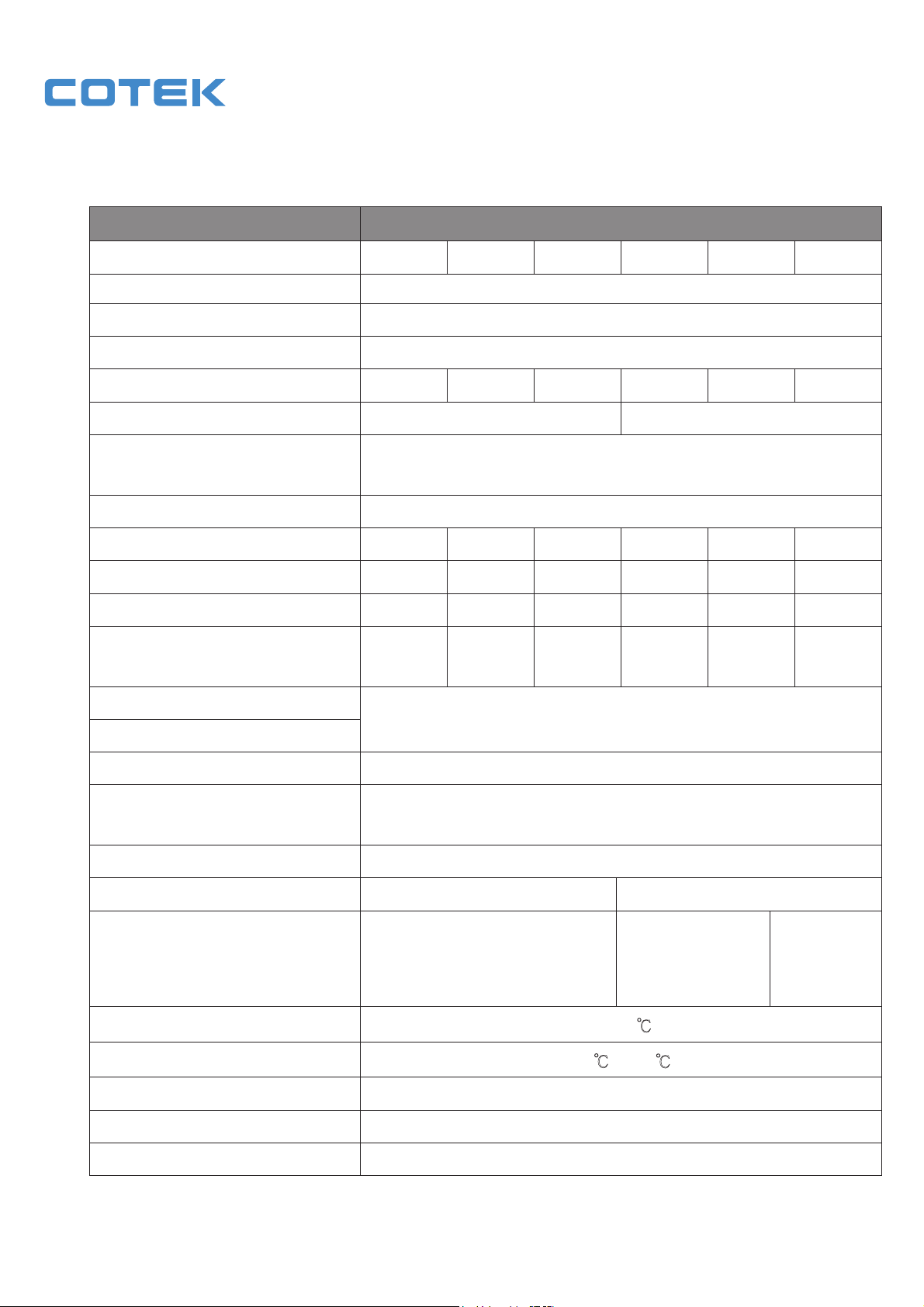
2-2. Electrical Performance
Specification
Item
SK700-112 SK700-124 SK700-148 SK700-212 SK700-224 SK700-248
Model No.
W007 rewoP tuptuO suounitnoC
W077 rewoP tuptuO mumixaM
W0041 ).xaM( gnitaR egruS
Input voltage 12V 24V 48V 12V 24V 48V
Output Voltage
100 / 110 / 120V +/- 5% 220 / 230 / 240V +/- 3%
Frequency
50 / 60Hz +/- 0.05%
(Switch Selections)
) %3 < DHT ( evaW eniS eruP mrofevaW tuptuO
Efficiency (full load) Max.
*1
89.0% 91.0% 92.0% 91.0% 93.0% 94.0%
No Load Current Draw (Max.) 1.25A 0.64A 0.31A 1.20A 0.60A 0.28A
Stand-By Current Draw (Max.) 0.25A 0.15A 0.08A 0.25A 0.15A 0.08A
10.5-15
21.0-30
42-60
10.5-15
21.0-30
42-60
Input Voltage Regulation
VDC
VDC
VDC
VDC
VDC
VDC
Input Level Indicator
Load Level Indicator
Protection
Safety Cert. Meet UL458 EN60950-1
Operating Temperature Range
Storage Temperature Range
Dimensions 273(L)*179(W)*71.5(H)mm / 10.75(L)*7.05(W)*2.81(H) Inch
Red / Orange / Green LED
DEL deR rotacidnI eruliaF
Overload, Short Circuit, Reverse Polarity (Fuse),
Over / Under Input Voltage, Over Temperature.
lanoitpO 8-RC / 6-RC tinU lortnoC etomeR
EN55022: 1997
A ssalC CCF CME
EN55024: 1997
EN61000-3-2: 1998
EN61000-3-3: 1995
e-mark
e13 022986
0 - 40 ℃
-30 to 70
℃
℃
naf gnilooc dellortnoc gnidaoL gnilooC
.sbL 4.5 / gk7.2 thgieW
Note: The specifications are subject to change without notice.
3

Specification
Model No.
Item
SK1000-112 SK1000-124 SK1000-148 SK1000-212 SK1000-224 SK1000-248
W0001 rewoP tuptuO suounitnoC
W0011 rewoP tuptuO mumixaM
W0002 )xaM( gnitaR egruS
Input voltage 12V 24V 48V 12V 24V 48V
Output Voltage
100 / 110 / 120V +/- 5% 220 / 230 / 240V +/- 3%
Frequency
50 / 60Hz +/- 0.05%
(Switch Selectable)
) %3 < DHT ( evaW eniS eruP mrofevaW tuptuO
Efficiency (full load) Max.
*1
89.0% 92.0% 93.0% 91.0% 94.0% 95.0%
No Load Current Draw (Max.) 1.43A 0.75A 0.38A 1.25A 0.65A 0.35A
Stand-By Current Draw (Max.) 0.25A 0.15A 0.09A 0.25A 0.15A 0.09A
10.5-15
21.0-30
42-60
10.5-15
21.0-30
42-60
Input Voltage Regulation
VDC
VDC
VDC
VDC
VDC
VDC
Input Level Indicator
Red / Orange / Green LED
Load Level Indicator
Protection
Operating Temperature Range
Storage Temperature Range
Dimensions 340(L)*182(W)*88(H)mm / 13.39(L)*7.17(W)*3.46(H) Inch
Note: The specifications are subject to change without notice.
DEL deR rotacidnI eruliaF
Overload, Short Circuit, Reverse Polarity (Fuse),
Over / Under Input Voltage, Over Temperature.
lanoitpO 8-RC / 6-RC tinU lortnoC etomeR
1-05906NE 854LU noitacifitreC ytefaS
A ssalC CCF CME
0 - 40
-30 to 70
℃
EN55022: 1997
EN55024: 1997
EN61000-3-2: 1998
EN61000-3-3: 1995
℃
℃
e-mark
e13 022694
naf gnilooc dellortnoc gnidaoL gnilooC
.sbL 8.8 / gk 4 thgieW
4

Specification
Model No.
Item
Input voltage 12V 24V 48V 12V 24V 48V
Output Voltage
Frequency
(Switch Selectable)
Efficiency (full load) Max.
No Load Current Draw (Max) 1.45A 0.75A 0.40A 1.40A 0.70A 0.40A
Stand-By Current Draw (Max) 0.28A 0.15A 0.09A 0.28A 0.15A 0.09A
Input Voltage Regulation
Input Level Indicator
Load Level Indicator
SK1500-112 SK1500-124 SK1500-148 SK1500-212 SK1500-224 SK1500-248
W0051 rewoP tuptuO suounitnoC
W0561 rewoP tuptuO mumixaM
W0003 )xaM( gnitaR egruS
100 / 110 / 120V +/- 5% 220 / 230 / 240V +/- 3%
50 / 60Hz +/- 0.05%
) %3 < DHT ( evaW eniS eruP mrofevaW tuptuO
*1
88.0% 91.0% 92.0% 90.0% 93.0% 94.0%
10.5-15
VDC
21.0-30
VDC
Red / Orange / Green LED
42-60
VDC
10.5-15
VDC
21.0-30
VDC
42-60
VDC
DEL deR rotacidnI eruliaF
Protection
Safety Certification Meet UL458 EN60950-1
Overload, Short Circuit, Reverse Polarity (Fuse),
Over / Under Input Voltage, Over Temperature.
lanoitpO 8-RC / 6-RC tinU lortnoC etomeR
EN55022: 1997
A ssalC CCF CME
EN55024: 1997
EN61000-3-2: 1998
EN61000-3-3: 1995
Operating Temperature Range
Storage Temperature Range
Dimensions 370(L)*191(W)*88(H)mm / 14.57(L)*7.52(W)*3.46(H) Inch
0 - 40 ℃
-30℃
to 70℃
Note: The specifications are subject to change without notice.
e-mark
e13 22876
naf gnilooc dellortnoc gnidaoL gnilooC
.sbL 65.01 / gk 8.4 thgieW
5

Specification
Model No.
Item
Input voltage 12V 24V 48V 12V 24V 48V
Output Voltage
Frequency
(Switch Selectable)
Efficiency (full load) Max.
No Load Current Draw (Max) 2.8A 1.5A 0.7A 2.64A 1.32A 0.65A
Stand-By Current Draw (Max) 0.60A 0.30A 0.15A 0.60A 0.25A 0.15A
Input Voltage Regulation
Input Level Indicator
Load Level Indicator
SK2000-112 SK2000-124 SK2000-148 SK2000-212 SK2000-224 SK2000-248
W0002 rewoP tuptuO suounitnoC
W0022 rewoP tuptuO mumixaM
W0004 )xaM( gnitaR egruS
100 / 110 / 120V +/- 5% 220 / 230 / 240V +/- 3%
50 / 60Hz +/- 0.05%
) %3 < DHT ( evaW eniS eruP mrofevaW tuptuO
*1
89.0% 92.0% 93.0% 91.0% 94.0% 95.0%
10.5-15
VDC
21.0-30
VDC
Red / Orange / Green LED
42-60
VDC
10.5-15
VDC
21.0-30
VDC
42-60
VDC
DEL deR rotacidnI eruliaF
Protection
Safety Certification Meet UL458 EN60950-1
Overload, Short Circuit, Reverse Polarity (Fuse),
Over / Under Input Voltage, Over Temperature.
lanoitpO 8-RC / 6-RC tinU lortnoC etomeR
EN55022: 1997
A ssalC CCF CME
EN55024: 1997
EN61000-3-2: 1998
EN61000-3-3: 1995
Operating Temperature Range
Storage Temperature Range
Cooling
Dimensions 368(L)*209(W)*166(H)mm / 14.49(L)*8.23(W)*6.53(H) Inch
Loading controlled cooling fan ( 65℃
0 - 40 ℃
-30℃
to 70℃
.sbL 8.91 / gk 9 thgieW
Note: The specifications are subject to change without notice.
e-mark
e13 22846
ON , 45℃ OFF)
6