

Page 1

N + 1
DC Power
System
Owner's
Manual
Please read this
manual BEFORE
installing the
unit
SEC-4825BRM
11001-SEC-4825BRM-0114.indd 1 14-01-07 1:15 PM
Page 2

OWNER'S MANUAL | Index
SECTION 1
Safety Instructions ................................................................. 3
SECTION 2
Layout, Dimensions & Input/Output Connections ................ 5
SECTION 3
Design & Principle of Operation ........................................... 7
SECTION 4
Protections ........................................................................ 19
SECTION 5
Installation ........................................................................ 21
SECTION 6
Operation ........................................................................ 23
SECTION 7
Limiting Electro-Magnetic Interference (EMI) ...................... 25
SECTION 8
Troubleshooting Guide ....................................................... 28
SECTION 9
Speci cations ..................................................................... 31
SECTION 10
Warranty ........................................................................ 33
2 | SAMLEX AMERICA INC.
11001-SEC-4825BRM-0114.indd 2 14-01-07 1:15 PM
Page 3
SECTION 1 | Safety Instructions
IMPORTANT SAFETY INSTRUCTIONS
SAVE THESE INSTRUCTIONS
This manual contains important Safety and Operating Instructions. Please read
before using this unit .
The following safety symbols will be used in this manual to highlight safety
and information:
Please read these instructions before installing or operating the unit to prevent
personal injury or damage to the unit.
1. DO NOT OPEN TO REDUCE RISK OF FIRE OR ELECTRIC SHOCK. THERE ARE NO USER
2. The unit should be grounded to reduce the risk of electric shock. It comes with
3. It is recommended that you return your power supply to a qualied dealer for any
4. To reduce the risk of electric shock, unplug the power supply from the outlet before
5. To reduce risk of damage to electric plug and cord, pull by plug rather than cord
6. An extension cord should not be used unless absolutely necessary. If an extension
WARNING!
!
Indicates possibility of physical harm to the user in case of non-compliance.
!
CAUTION!
Indicates possibility of damage to the equipment in case of non-compliance.
!
WARNINGS!
SERVICEABLE PARTS INSIDE—REFER TO QUALIFIED SERVICE PERSONNEL.
attached power cord that has a 3 prong, grounded 30A, NEMA L5-30P plug. The
grounding prong of the plug is internally connected to the chassis of the unit. When
the power cord is plugged into the corresponding NEMA L5-30R outlet, the chassis
of the unit is automatically connected to the Earth Ground through the Equipment
Grounding Conductor that is connected to the grounding slot of the outlet. The power cord must be plugged into a corresponding NEMA L5-30R outlet that is properly
installed and grounded in accordance with all local codes and ordinances. Never alter
the power cord that has been provided. If the plug of the cord will not t the outlet,
have a proper outlet installed by a qualied electrician. Improper connection can
result in risk of electric shock.
service or repair. Incorrect assembly may result in electric shock or re.
attempting any maintenance or cleaning. Turning off controls will not reduce this risk.
when disconnecting the unit.
cord is used, make sure that it has 3-prong, grounded male plug (NEMA L5-30P) and
SAMLEX AMERICA INC. | 3
11001-SEC-4825BRM-0114.indd 3 14-01-07 1:15 PM
Page 4
SECTION 1 | Safety Instructions
3-prong, grounded female receptacle (NEMA L5-30R). The size of the current carrying
conductors should be at least AWG#10 for NEMA L5-30.
7. Place the unit in an area that will allow air to ow freely around the unit. DO NOT
block or obstruct vent openings on the sides and at the back or install the unit in an
enclosed compartment.
8. Keep the unit away from moisture and water.
9. NEVER OPERATE TWO OR MORE UNITS IN PARALLEL.
10. Precautions when working with batteries.
- Batteries contain very corrosive diluted Sulphuric Acid as electrolyte. Precautions should be
taken to prevent contact with skin, eyes or clothing.
- Batteries generate Hydrogen and Oxygen during charging resulting in evolution of explosive gas mixture. Care should be taken to ventilate the battery area and follow the battery
manufacturer’s recommendations.
- NEVER smoke or allow a spark or ame near the batteries.
- Use caution to reduce the risk of dropping a metal tool on the battery. It could spark or
short circuit the battery or other electrical parts and could cause an explosion.
- Remove metal items like rings, bracelets and watches when working with batteries. The
batteries can produce a short circuit current high enough to weld a ring or the like to metal
and thus cause a severe burn.
- If you need to remove a battery, always remove the Negative Ground Terminal from the
battery rst. Make sure that all the accessories are off so that you do not cause a spark.
CAUTIONS!
!
1. Please ensure that the battery is connected with correct polarity - Positive of the battery to the “Battery +” terminal and the Negative of the battery to the “Battery -”
terminal. Reversal of polarity will blow external Fuse F1. DAMAGE DUE TO REVERSE
POLARITY IS NOT COVERED UNDER WARRANTY.
2. Protect the unit against AC line input transients. Use Transient Suppressor in line with
the AC input.
4 | SAMLEX AMERICA INC.
11001-SEC-4825BRM-0114.indd 4 14-01-07 1:15 PM
Page 5
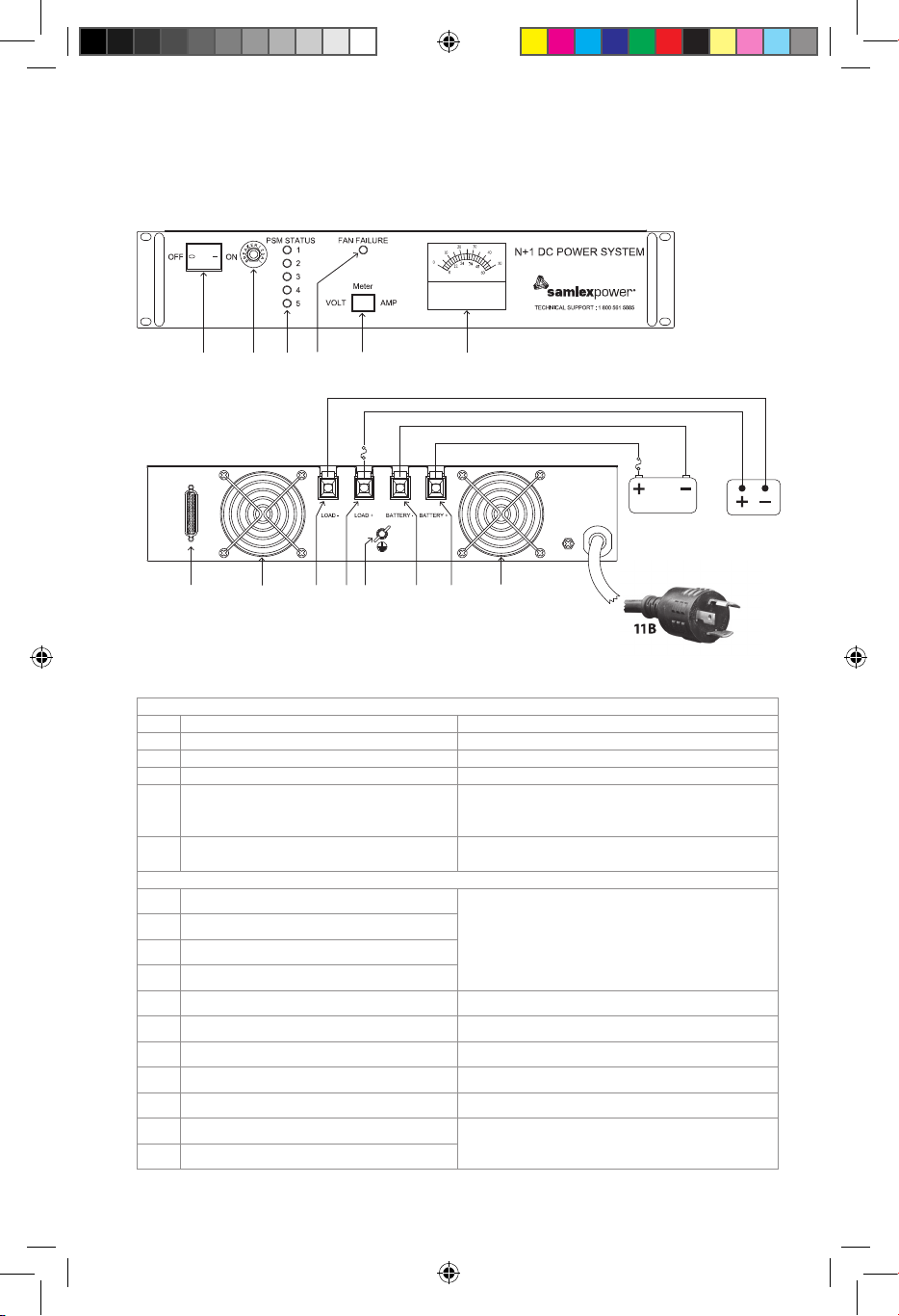
SECTION 2 | Layout, Dimensions &
Fig. 2.1 FRONT VIEW
1
1B
Input/Output Connections
1 2 5 346
F2
F1
48V Battery
12 9 98A8B107A7B 11A
Fig. 2.1 BACK VIEW
11B
Fig. 2.1 Layout and Input/Output Connections
Legend - Fig 2.1
FRONT VIEW
1
AC Power ON/OFF Switch Illuminates RED when ON
2
AC Input Breaker 25A.
3
DC Volt Meter / Ammeter Voltage / current on Load Terminals
4
Voltmeter / Ammeter Selector Switch Switches display on Voltmeter / Ammeter (3)
Green LED for Power Supply Modules (PSM)
5
1 to 5
Red LED for fan failure or over temperature
6
of heat sink on the PSM
BACK VIEW
7A Positive (+) Load Terminal
7B Negative (−) Load Terminal
8A Positive (+) Battery Terminal
8B Negative (−) Negative Terminal
9 Cooling Fan 2 x 48V fans. Run continuously
10 Grounding Lug Connect to Earth Ground / System Ground
11A Attached AC Input Power Cord 3 Conductors - each AWG #12
11B AC Input Power Cord Plug 30A, NEMA L5-30P
12 DB-25, D-Sub Connector For remote signaling (Pin Out - Fig 3.2)
F1 External Battery Side Fuse
F2 External Load Side Fuse
STEADY ON: PSM is operating normally
BLINKING: No output. PSM is not synchronizing
OFF: No output. Defective
STEADY ON: Fan failure or PSM over temperature
TUBULAR HOLE: 5/16” Diameter
SET SCREW: 5/16” X 3/8” Long x 24 TPI
25A, 80V (Not supplied)
- ATO Style, FKS Series by Littelfuse
- Part No. 166.7000.525
48V Load
SAMLEX AMERICA INC. | 5
11001-SEC-4825BRM-0114.indd 5 14-01-07 1:15 PM
Page 6
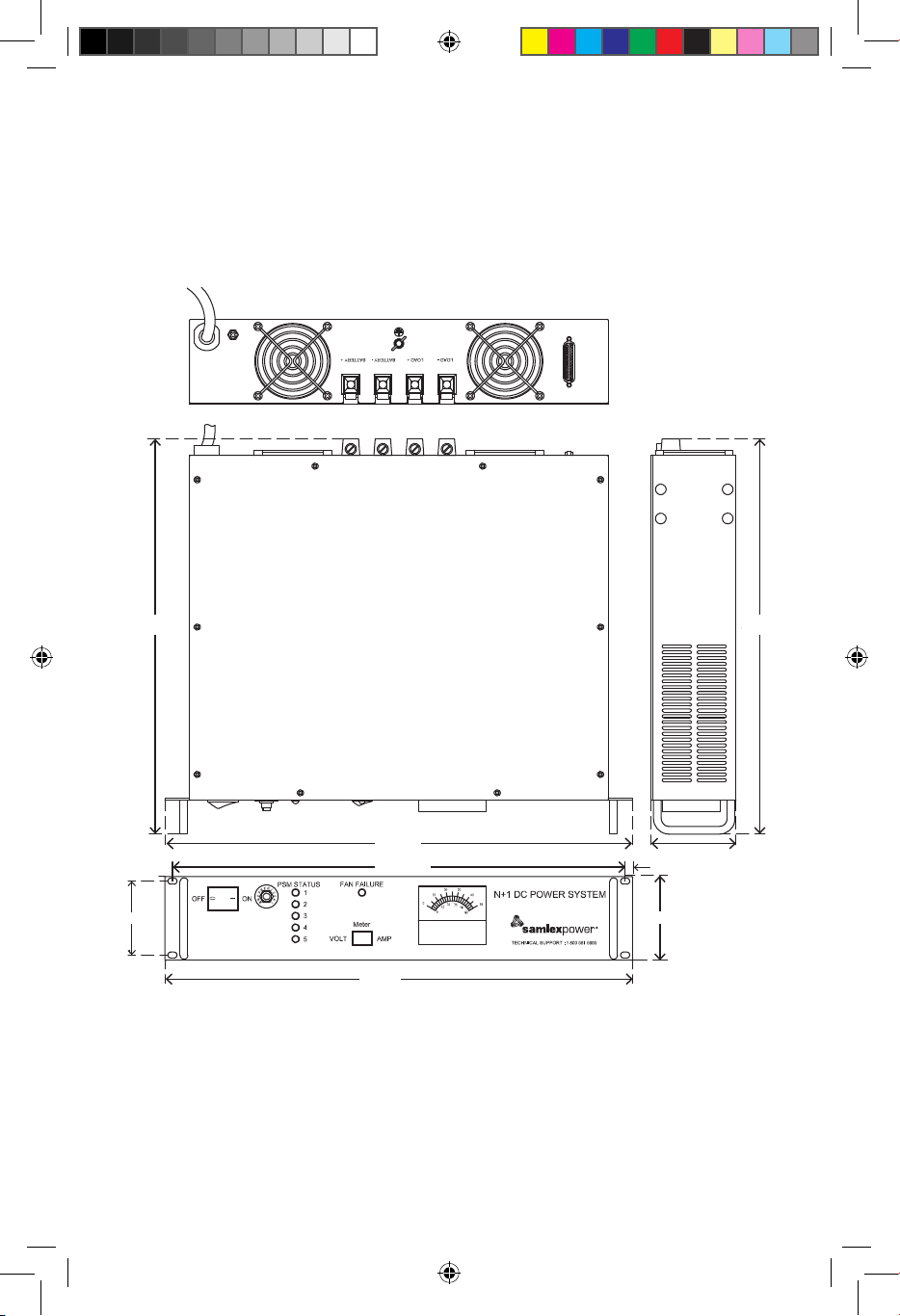
SECTION 2 | Layout, Output Connection
& Dimensions
1. Dimensions Overall
(including protrusions)
Wide(W): 482.6 mm / 19.00”
Depth (D) : 407.6 mm / 16.05”
407.6
407.6
Height (H): 87.7 mm / 3.45”
2. Dimensions (Mounting Holes)
Width (W): 466.73 mm / 18.38”
Height (H): 76.2 mm / 3.00”
407.6
407.6
482.6
466.73
76.2
482.6
Fig. 2.2 Dimensions
6 | SAMLEX AMERICA INC.
11001-SEC-4825BRM-0114.indd 6 14-01-07 1:15 PM
7.94
87.7
87.7
Page 7

SECTION 3 | Design & Principle of Operation
DESCRIPTION
SEC-4825BRM is a Switch Mode Power Supply (SMPS), which converts 120 VAC, 50/60 Hz
to 48VDC Nominal (actually 54.8VDC at no load to 54.2V at 25A). It has additional provision for 48V battery backup with 2A charging in conjunction with external 48V Lead
Acid Battery (not supplied).
FEATURES
• 19”,2U(3.5”)heightRackMountdesign
• AdvancedSwitchModeTechnology
• N+1Redundancy:5x5APowerSupplyModulesoperateinparallelunder
forced current share control
• RemotemonitoringthroughOptoIsolated,OpenCollector/OpenEmitter
output signals
• Reliable,48VDCUninterruptiblePowerSource(DCUPS)inconjunction
with external 48V Lead Acid backup Battery (not supplied)
• Highefciencyandcompact
• Protectedagainstshortcircuit,overload,overvoltageandovertemperature
PRINCIPLE OF OPERATION
The unit consists of 2 Sections - Switch Mode Power Supply (SMPS) Section and Battery
Backup and Charging Section.
The SMPS Section is designed using advanced switch-mode technology and active load
share circuitry for high reliability, high efciency and minimum size and weight. It is
modular in construction consisting of 5 x 5A Power Supply Modules (PSM) that are
connected in parallel and operate under forced current share control to deliver a total
of 25A. Each PSM is a stand-alone, 55V Power Supply, which delivers up to a maximum
of 5A continuous. By equalizing the output currents, uniform thermal stress of the
individual PSMs is ensured which has utmost importance for long-term reliability of electronic components. The operating principle of current share mechanism is to measure
the output current of each PSM and to modify the output voltages of the 5 PSMs until
all the 5 PSMs deliver equal output current. Typically, the output currents of the 5 paralleled PSMs will be within 10% of each other at full output current. The module with
the highest voltage at switching ON automatically assumes the role of a Master and the
others operate as Slaves. Each PSM is required to be interconnected with one another to
a common “SHARE BUS” through a pair of parallel pins marked “JUMP 1” and jumper
wires (Fig. 3.5).
For proper operation of Current Share Control Circuitry / Master - Slave operation, a minimum load current is required to ow through each PSM to produce adequate feed back
signal. This minimum pre-load current is provided by the sum of the currents drawn by
the 2 cooling fans and by an internal static load resistor connected across the load output
terminals. This internal pre-load current* is kept to the minimum to reduce dissipation.
SAMLEX AMERICA INC. | 7
11001-SEC-4825BRM-0114.indd 7 14-01-07 1:15 PM
Page 8

SECTION 3 | Design & Principle of Operation
* NOTE: It is likely that due to drift in the pre-set values of components, the minimum
internal preload current may not be suf cient to provide adequate feedback signal
strength resulting in shut down of one or more modules when no external load is
present (The associated PSM Status LED will ash and also, the associated signal for
remote indication will oscillate between High and Low). As soon as external load is
applied to the unit, the feed back signal strength will increase and the PSM(s) that
were shut down will also operate normally.
The output is delivered through an isolating Schottky diode to enable connection of
external 48V battery (not supplied) for un-interrupted DC power output. The external
backup battery is kept charged by “Taper Type of Float Voltage Charging” through a
current limiting series resistor that limits the maximum charging current to 2A when the
battery is completely discharged.
The SMPS Section along with the Battery Backup and Charging Section work as a DC
Uninterruptible Power Source (DC UPS) in conjunction with an external 48V, Lead Acid
backup battery (battery is not supplied). As long as 120VAC input power is available,
the unit will put out 54.8VDC to 54.2VDC at the Load Terminals (7A, 7B - Fig 2.1). At
the same time, charging current of up to a maximum of 2A (when battery is completely
discharged to Standing Voltage of 42.8V) will be fed through the Battery Terminals (8A,
8B - Fig 2.1) to charge the external battery. The voltage at the Battery Terminals (8A, 8B
- Fig 2.1) will always be clamped to the actual voltage of the battery corresponding to its
State of Charge. If AC input power fails, the DC load will be instantaneously transferred
to the external 48V backup battery and the battery will start discharging. When AC
input power is restored, the DC load will once again be transferred instantaneously to
the Power Supply Section and the external backup battery will be recharged and kept in
charged condition all the time at oat Voltage of 54V to 54.6V (when fully charged). If
battery backup function is not used (external 48V backup battery is not connected), the
unit will work as a normal 48V nominal Power Supply.
N+1 Redundancy
5 Power Supply Modules operating in parallel with equal current sharing provides
redundancy. Chance of failure of all the 5 modules is reduced tremendously. If say one
module fails, the remaining 4 modules will share the load current equally. Such redundancy is also called N+1 redundancy i.e. if “N” number of paralleled modules are
required to service a certain load, the unit should have 1 additional module (total “N+1”
modules) to provide redundancy. For example, if the rated load drawn from this unit is
20A, 4x5A modules will be required. Using 1 additional 5A module (total 25A) will have
the capacity to service the full load of 20A even if 1 module fails.
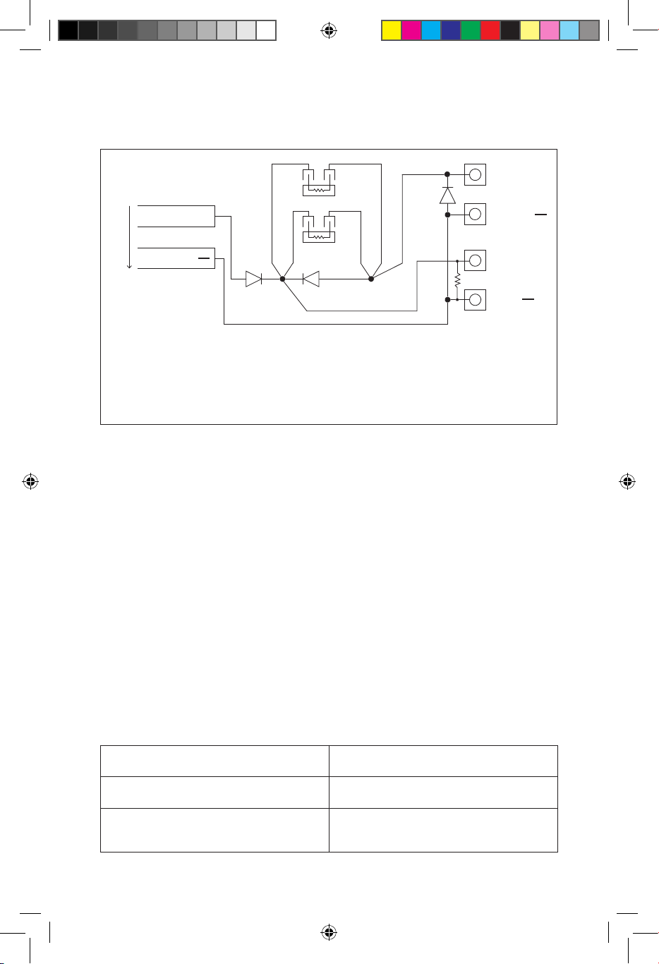
OPERATION OF BATTERY BACK-UP AND CHARGING SECTION
Please refer to the schematic at Fig 3.1 (page 9).
Regulated output voltage of 55VDC from the modules (measured at screw terminals
S5 and S6 (Fig. 3.4) is fed to the Positive and Negative DC bus bars and from there to
the output terminals LOAD (+) and LOAD (−) through the isolating Schottky Diode D1.
Although the output voltage at the module terminals S5 and S6 (Fig.3.4) or at the
8 | SAMLEX AMERICA INC.
11001-SEC-4825BRM-0114.indd 8 14-01-07 1:15 PM
Page 9
SECTION 3 | Design & Principle of Operation
R
BATTERY
BATTERY
LOAD
+
LOAD
POSITIVE BUS BAR
55V
from
PSM
NEGATIVE BUS BAR
+
R1
D3
R2
D2D1
LEGEND
D1, D2 Schottky Diode, 40CPQ060 by International Rectier
D3 10A, 600V Diode “10A6” for reverse polarity protection
R1, R2 Power Resistor 12 Ohm, 35W
R Static Load Resistor, 1K, 5W
Fig 3.1 Schematic - Battery Backup
common DC bus bar (before the Schottky Diode D1) is tightly regulated at the preset
value of 55VDC, the voltage at the output terminals Load (+) and Load (−) will vary
slightly due to the forward voltage drop “Vf” of the isolating Schottky Diode D1 and
the drop along the DC bus bar and wiring. The voltage at the output terminals LOAD
(+) and LOAD (−) will be as follows:
• Atnoexternalload Approximately54.8VDC
• At25Aload Approximately54.2VDC
+
When there is a requirement of un-interrupted DC power to the load, an external 48V
battery should be connected at the terminals Battery (+) and Battery (−). When input
AC power is available, the load current is supplied by the Power Supply Section through
Isolating Schottky Diode D1. At the same time, the battery is charged to Float Voltage
Level by “Taper Type of Charging” through 2 x 12 Ohm resistors R1 & R2 in parallel with
an effective series resistance of 6 Ohm. This effective series resistance of 6 Ohm will limit
the maximum charging current to 2A. The charging current will be determined by the
following equation (Battery’s internal impedance and battery cable resistance have been
disregarded as their values are negligible as compared to the 6 Ohm effective series
resistance):
Charging Current = (Load Terminal Voltage – Battery’s Intrinsic
Maximum Charging Current (At completely
discharged voltage of 42.8V)
Charging current when fully charged to maximum Float Voltage of 54.6V
State of Charge Voltage) ÷ 6 Ohm
= (54.8V – 42.8V) ÷ 6 Ohm = 2A
25 mA (0.1% of Ah capacity of the battery to
compensate for self-discharge. Battery with
25Ah capacity has been considered)
SAMLEX AMERICA INC. | 9
11001-SEC-4825BRM-0114.indd 9 14-01-07 1:15 PM
Page 10

SECTION 3 | Design & Principle of Operation
From the above equation, it will be seen that the battery will be charged at a maximum
charging current of around 2A when the battery is completely discharged to Standing Voltage of 42.8V and the charging current will taper to a very low value of around
25mA when the battery is charged to Float Voltage Level of 54.6V.
If input A.C. power is interrupted, the external battery feeds the load instantaneously
through the Schottky Diode D2 (D2 will be forward biased and will by-pass resistors R1
& R2). Voltage available to the load will be approximately 0.2V lower than the battery
voltage due to forward voltage drop across D2. Availability of AC power is signaled for
remote monitoring through opto-isolated signal through D-Sub Connector (Pins 2 and
16 of D-Sub Connector, Fig 3.2. Also see below under “Remote Monitoring of Operational Status”). This signal may also be used to indicate that the load is being powered
by battery (In case external battery is used for battery back-up). When AC input power
returns, load current will be supplied by the Power Supply Section, Diode D2 will be reverse biased and the discharged battery will be taper charged through 6 Ohm effective
resistance of R1& R2.
* NOTE: The value of charge limiting resistors R1 and R2 is based on a typical 48V,
25Ah deep cycle marine battery. If a different type of battery is used, the value of
the resistor should be adjusted to meet associated charging requirements.
REMOTE MONITORING OF OPERATIONAL STATUS
A provision has been made for remote monitoring of the following operational
conditions and parameters:
a) Operational status of the 5 Power Supply Modules (PSM)
b) Failure condition of the cooling fan(s)
c) Availability of AC input power (Through 120VAC to 5VAC transformer)
d) Output voltage measurement (Across Load Terminals)
e) Output current measurement (Voltage across an internal shunt with Shunt Ratio of
25 mV / 50A or 0.5 mV per Amp)
Signals for remote monitoring of operating conditions at Srls (a), (b) and (c) above are
transmitted to the remote receiving device through open Collector and open Emitter
pins of phototransistor of internal Opto-Isolator (Figs 3.2 & 3.3A).
Outputs for voltage and current measurements at Serials (d) and (e) above are direct
analogue voltages.
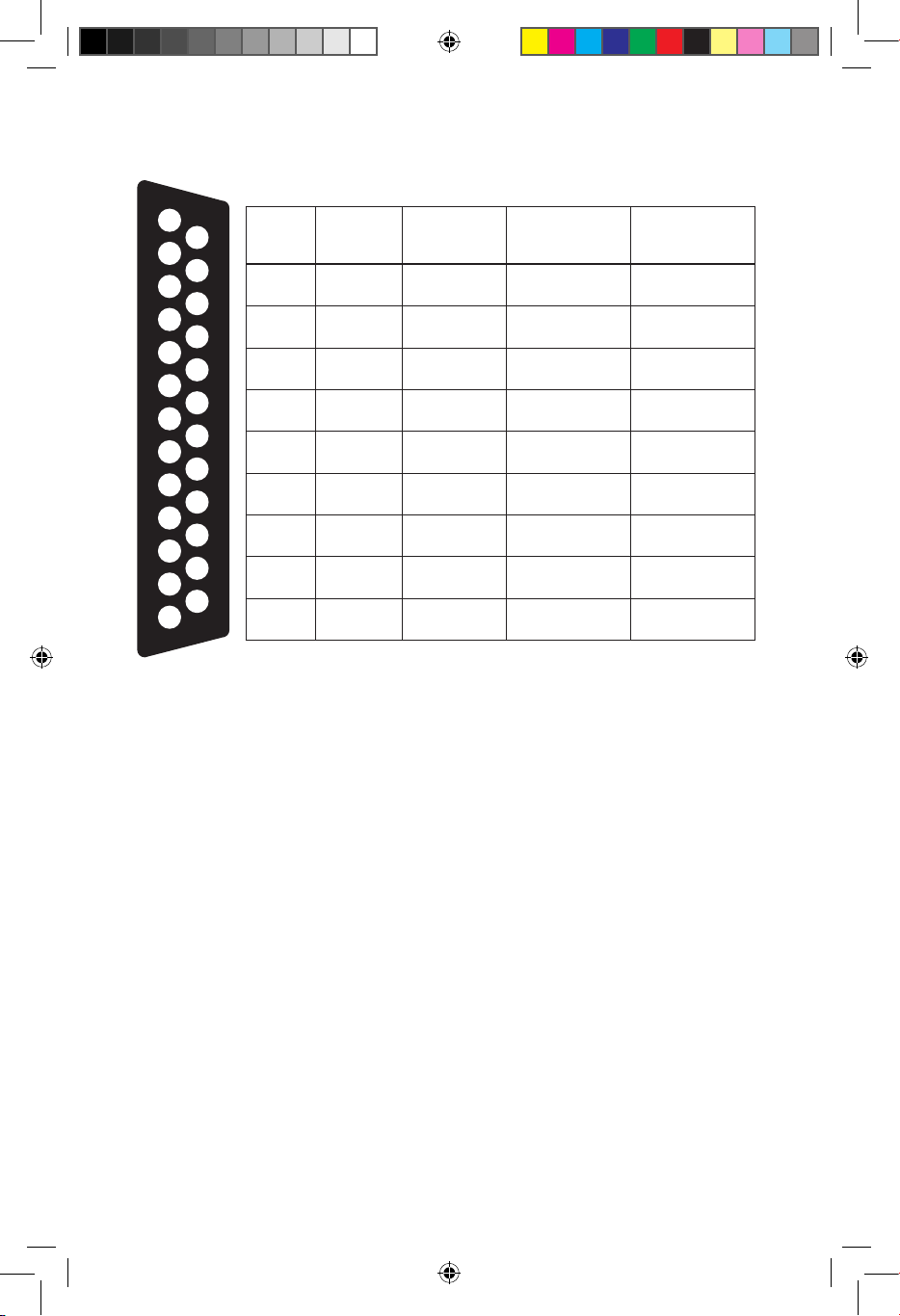
The Pin Out of the 25 Pin D-Sub Connector (12, Fig 2.1) providing the above signals for
user interface is given at Fig 3.2.
10 | SAMLEX AMERICA INC.
11001-SEC-4825BRM-0114.indd 10 14-01-07 1:15 PM
Page 11
SECTION 3 | Design & Principle of Operation
1
2
3
4
5
6
7
8
9
10
11
12
13
14
15
16
17
18
19
20
21
22
23
24
25
Item Pin No.
1
2
3
4
5
6
7
8
9
2
16
12
19
7
20
8
21
9
22
10
23
11
24
25
13
18
6
Color Code
of Wire
Black
White
Orange
Green
Gray
Violet
Violet
Blue
Blue
Greeb
Green
Yellow
Yellow
Orange
Red
Black
Gray
Blue
Output Pins of
Opto Isolator
Collector
Emitter
Collector
Emitter
Collector
Emitter
Collector
Emitter
Collector
Emitter
Collector
Emitter
Collector
Emitter
- Voltmeter +
- *Ammeter +
Notes:
† For operational conditions at Items 1 to 7, the Transistor Switch inside the
Opto Isolator is in “Saturation” condition (near short circuit between
Collector and Emitter terminals)
* Shunt Ratio 25mV/50A or 0.5mV/Amp.
Fig. 3.2 Pin Out of 25 Pin D-Sub Connector (12, Fig 2.1) for Remote Monitoring
†Operational
Condition or
Parameter (High)
AC input is
available
Fan failure
PSM 1 Normal
PSM 2 Normal
PSM 3 Normal
PSM 5 Normal
PSM 5 Normal
Voltmeter -
*Ammeter -
OPTO-ISOLATED TRANSFER OF SIGNALS FOR REMOTE MONITORING
In this power supply, signals for remote indication of operating conditions at Serials (a),
(b) and (c) on page 10 are transmitted to the remote receiving device through open
Collector and open Emitter pins of NPN phototransistor of internal Opto-Isolator (Fig 3.2
above and Fig 3.3A on page 12). The NPN phototransistor can provide a maximum of
50 mA with a Collector to Emitter voltage of up to 35V. Use of opto-isolated signal
transfer ensures the following at the receiving location:
• Isolatesnoise,groundloops,and/orhighvoltagesfromthepowersupply
from being fed to the external remote monitoring device.
• The+Vccvoltagethatisconnectedtothepull-upresistor(s)/alarmsandrelaysfor
generating alarm signals at the receiving monitoring device (Figs 3.3 B to D, page 12)
comes from an external voltage source and hence, maximum isolation is provided
• AbilitytogenerateTTLlogicsignalswithVccof3.3V/5V(Fig3.3Bfor5VVcc)
• Driverelays/LEDswithVcc of up to 35VDC (e.g. 5V / 12V / 24V) and drive current of
up to 50 mA (Figs 3.3C and 3.3D)
• Abilitytocombinethesignals(OR’d)toformasinglesignalsharingcommon
Logic Ground
11001-SEC-4825BRM-0114.indd 11 14-01-07 1:15 PM
SAMLEX AMERICA INC. | 11
Page 12

SECTION 3 | Design & Principle of Operation
PSM1 PCB
“M-20-48V”
5V
PSM GND
LED 1
PIN 1 is
HIGH (5V)
when PSM 1
is Normal
GR AY
VIOLET
Opto-Isolator
PCB “M-20-P”
IC-1
1 4
C
E
2
VCE – Max 35V
IC – Max 50mA
DB-25 Connector
GR AY
VIOLET
3
Fig. 3.3A: Schematic for Remote Signalling for “PSM 1 Normal”
+ Vcc = 5V
R
= 10K
Pull Up
From Fig. 3.3A
7
20
Vcc Ground
To Micro-controller
Fig. 3.3B: 5V TTL Logic Drive
+ V
= 5V / 12V / 24V (Max. 35V)
cc
NC
Common
NO
From Fig. 3.3A
IN4001
7
20
Vcc Ground
Relay 5V / 12V / 24V:
Choose coil resistance
to limit coil current
to < 50 mA
7
7
To Figures:
3.3B/3.3C/3.3D
20
20
PSM 1 Normal – Low (0 to 0.5V)
PSM 1 Defective – High (2.7V to 5V)
PSM 1 Normal – Relay energizes
PSM 1 Defective – Relay de-energized
Fig. 3.3C: 5V / 12V / 24V Relay Drive
+ Vcc = 5V/12V/24V (Max. 35V)
1.5K
7
From Fig. 3.3A
20
PSM 1 Normal – LED “ON”
LED
PSM 1 Defective – LED “OFF”
Vcc Ground
Fig. 3.3D: LED Drive
12 | SAMLEX AMERICA INC.
11001-SEC-4825BRM-0114.indd 12 14-01-07 1:15 PM
Page 13

SECTION 3 | Design & Principle of Operation
Principle of operation is explained in Figs 3.3A to 3.3D below using example of remote
monitoring of the operational status of Power Supply Module No. 1 (PSM1).
Operation Inside the Power Supply
Please refer to Fig 3.3A.
When PSM1 is operating normally, 5V (HIGH) drive signal is fed to Pins 1 and 2 of Infrared Diode inside the Opto-Isolator “IC1”. The diode conducts and optically transfers
HIGH Base drive condition to the NPN Photo-Transistor with Pin 4 (Open Collector) and
Pin 3 (Open Emitter). The Photo-Transistor will be in “Saturated” condition (near short
circuit between Collector (Pin 4) and Emitter (Pin 3). Pins 4 and 3 are connected to Pins 7
and 20 respectively of the DB25 Connector (Fig 3.2).
Operation at Remote Monitoring Location
Monitoring of status from the DB-25 Connector can be undertaken at the remote
monitoring location in 3 ways shown in Fig 3.3B, 3.3C and 3.3D.
S3
S4
S1
L N
S2
+
LED 1
LED 2
VR1
F1
VCC
+
S-5
JUMP 1
S6
NOT TO SCALE
Legend
S1 to S4 Holes for 4 screws to fasten the module to the chassis
S5 & S6 Holes for 2 screws to connect to the Positive & Negative output BUS Bars
L & N L (Line) and N (Neutral) terminals for 120V, 60 Hz input power supply wires
LED 1 Terminal for remote indication of PSM status
LED 2 Terminal for “LED” PSM status (Front Panel)
JUMP 1 Jumper terminal for connecting share BUS wire
VCC Connector for feeding Vcc to PCB for fan monitoring
F1 Fuse: 250V, 4A
VR1 Potentiometer for output voltage adjustment
Figure 3.4 Layout of Power Supply Module “M20-48V”
SAMLEX AMERICA INC. | 13
11001-SEC-4825BRM-0114.indd 13 14-01-07 1:15 PM
Page 14

SECTION 3 | Design & Principle of Operation
1
2
1
2
1
2
1
2
1
2
PSM 1 PSM 2
PSM 3
PSM 4 PSM 5
PCB (Printed Circuit Board)
Jump 1 Jump 1 Jump 1 Jump 1 Jump 1
PSM 1 PSM 2
Jump 1 Jump 1 Jump 1 Jump 1 Jump 1
LEGEND:
1. Female terminal for the Daisy Chain Wire Connector
2. Male, 2-pin terminal marked “Jump 1” on the Power Supply Module
PSM 3
1
2
1
2
PSM 4 PSM 5
1
2
PCB (Printed Circuit Board)
Fig 3.5 Daisy Chaining of Share Bus Jumps (Jump 1)
Unused
female
socket
Shorting Link
1
2
1
2
Fig 3.6 Shorting Unused Jump 1 Daisy Chain Wire Connector
OUTPUT VOLTAGE ADJUSTMENT
As explained earlier, the Power Supply Section of this unit has 5 Power Supply Modules
operating in parallel under forced current share control. Each module has rated current
output of 5A and hence, the total rated current output of the unit is 25A. For the forced
current share / Master –Slave operation to work properly, it is important that the “set
output voltage” of each of the 5 modules is exactly the same. If the output voltage of
any module is below the “set voltage”, its current share control circuitry (slave operation) will not function properly and it’s associated “PSM x” LED will start ashing. The
other modules which are putting out the “set voltage” will function normally under
Master/ Slave operation and their “PSM x” LEDs will remain continuously lighted and
the output voltage of the common DC bus (before Schottky Diode D1) will be equal to
the “set voltage”. If the output voltage of any module is higher than the “set voltage”,
it will become the Master and it’s associated “PSM x” LED will remain continuously
lighted. However, the other Modules with voltage lower than the “set voltage” will
14 | SAMLEX AMERICA INC.
11001-SEC-4825BRM-0114.indd 14 14-01-07 1:15 PM
Page 15

SECTION 3 | Design & Principle of Operation
not be able to function normally as Slaves and their associated LEDs “PSM x” will ash
randomly.
The output voltage of the common DC bus (before Schottky Diodes D1) will read the
higher voltage of this module.
The output voltage of each module measured at the module output pads under S-5
and S-6 (See Fig.3.4) is factory pre-set at 55V to provide no load voltage of 54.8V at the
Load Terminals. A precision multi-turn potentiometer VR1 is provided for ne adjustment of the output voltage of each of the modules. The adjustment range of module
output voltage is 53V to 56.3V.
If the output voltage of the modules is required to be set to a value other than the
preset value of 55V, the individual output voltage of each of the 5 modules will be required to be adjusted one by one to the same new “set voltage” within the adjustment
range of 53V to 56.3V. This is done by feeding AC input power to only the module
under adjustment and disconnecting AC input power to the other modules. Similarly,
during operation and during replacement of defective module with new module, the
output voltage of the all the individual modules will be required to be adjusted to the
desired value.
As explained under Operation Of Battery Back Up And Charging Section on page 8,
although the output voltage of the module at terminals S5 and S6 (Fig.3.4) or at the
common DC bus (before the Schottky Diode D1) is tightly regulated at the preset value
of 55V, the voltage at the output terminals Load (+) and Load (−) will vary due to the
forward voltage drop of the isolating Schottky Diode D1 and the drop along the DC
bus and wiring. Table 3.1 below gives details of voltage settings and actual voltages
available under no load and under loaded conditions.
TABLE 3.1 VOLTAGE SETTINGS
Module Output
Voltage at Terminals
S5 and S6 (Fig 3.4)
Preset Voltage 55V
Adjustment range:
53V to 56.3V
Load Current
(Combined Current of
5 paralleled Modules)
No load (0A) 0.2V 54.8V
15A 0.6V 54.4V
25A 0.8V 54.2V
No Load 0.2V 52.8V to 56.1V
15A 0.6V 52.4V to 55.7V
25A 0.8V 52.2V to 55.5V
Forward Voltage drop
“Vf” Across Schottky
Diode D1
Voltage Available at
Load Terminals Load (+)
and Load (−)
(Module Voltage - “Vf”)
Procedure for Adjusting Output Voltage of Modules
1. Switch OFF the unit and unplug the AC input power cord.
2. The output voltage of each individual module is adjusted one by one starting from
say, the left most module – PSM 1 and progressing to the right most module – PSM
SAMLEX AMERICA INC. | 15
11001-SEC-4825BRM-0114.indd 15 14-01-07 1:15 PM
Page 16

SECTION 3 | Design & Principle of Operation
No. 5. AC input is connected only to the module being adjusted. AC input to the
remaining modules is disconnected.
Procedure for Adjusting Output Voltage of Modules (continued)
3. Prepare PSM 1 for adjustment by Removing AC input connections (female quick
connect terminals connected to the L and N male tab terminals on the module –
Fig. 3.4) from PSM Nos. 2, 3, 4 and 5. Temporarily insulate these female quick connect terminals with insulating tape for safety. Now, only PSM No. 1 can be
energized.
4. Switch ON the power supply. Only PSM No. 1 will operate. Adjust the output
voltage of this module to the desired “set value” with the help of potentiometer
VR1 (Fig.3.4). Measure output voltage of the module at the screw terminals S5
and S6 (Fig. 3.4).
5. Switch OFF the power supply. Remove the AC input connections from PSM No. 1.
Temporarily insulate these terminals with insulation tape.
6. Prepare PSM No 2 for adjustment by removing temporary insulation from the
AC connectors for PSM 2 and connect them to PSM 2. Now only PSM 2 can be
energized.
7. Switch ON the power supply. Only PSM No. 2 will operate. Adjust the output
voltage of this module to the same “set value” with the help of potentiometer
VR1 (Fig. 3.4). Measure the output voltage of the module at the screw terminals
S5 and S6 (Fig. 3.4)
8. Continue to adjust the voltage of the remaining Module Nos. 3, 4 and 5 individually as explained above making sure that the AC input power is connected to only
the module being adjusted.
9. After the output voltage of all the 5 modules has been adjusted to the same
“set value”, connect the AC input back to all the ve modules.
10. Power ON the unit and check that all the 5 “PSM Status” LEDs are lighted. This
will con rm that the voltage adjustment has been completed successfully.
NOTE: As explained under Principle of Operation on page 7, it is likely that the
minimum internal preload current for the new value of the output voltage may not
be suf cient to provide adequate feedback signal strength resulting in shut down of
one or more PSM(s) when no external load is present (The associated PSM Status
LED will ash and also, the associated signal for remote indication will oscillate
between High and Low). In such a case, apply an external load to increase the feed
back signal strength. If there is no other defect, the PSM(s) that were shut down will
also operate normally.
16 | SAMLEX AMERICA INC.
11001-SEC-4825BRM-0114.indd 16 14-01-07 1:15 PM
Page 17

SECTION 3 | Design & Principle of Operation
INSTALLATION AND REMOVAL OF POWER SUPPLY MODULES
Please refer to Figs. 3.4, 3.5 and 3.6 (pages 13 & 14).
Replacing Defective Module with new Module
Replacement Module can be ordered under Model No. “SEC-0548MPSB”.
The optional module comes with an LED and LED holder. It’s output voltage is
pre-set at 55V.
Removal and replacement procedure is given below:
1. Switch OFF 120 VAC, 60 Hz input power and unplug the power cord from the
main outlet.
2. Remove the top cover plate by unscrewing the 10 screws.
3. Remove the AC input power supply wires from terminals “L” and “N” of the
defective module (Fig 3.4).
4. Remove connectors from terminals “LED 1 & LED 2” (Fig 3.4). Terminal marked
LED2 is used for the front panel LED under “PSM Status”. Terminal marked LED1 is
used to feed 5V “PSM ON” drive signal to the associated Infrared Diode of optocoupler on the small opto-coupler PCB & from there it is fed to DB-25 Connector as
Open Collector / Open Emitter signal for remote indication.
5. Remove female connector of the Daisy Chained “SHARE BUS” wire loop connected to male terminal “JUMP1” on the module (Fig 3.4, Fig 3.5).
6. Each module sits on 6 stand-offs under holes S1 to S6 (Fig.3.4). Remove these
screws and then remove the defective Module.
7. If this module has Temperature Sensor mounted on its heat sink, remove the Temperature Sensor by removing its holding screw.
8. Place the new module on the stand-offs with the L an N terminals (Fig. 3.4)
towards the front panel. Align the holes and x the module with the 6 screws.
WARNING! Please ensure that screws S5 and S6 are very tight as the pads under
these two screws connect the output of the module to the DC bus bar underneath. A loose connection under these screws will result in sparking, overheating
and consequent damage to the module.
9. As explained earlier under “Procedure for Adjusting Output Voltage of Modules”
(page 15), the output voltage at the individual modules (measured at points
S5 & S6 of the module as shown at Fig. 3.4) is required to be set exactly at the
same voltage for proper current share control. Each module is factory preset at a
voltage of 55V with the help of potentiometer VR1. Although the new module
SEC-0548MPSB is factory preset at 55V, it may differ slightly due to tolerance. It is,
therefore, necessary to ensure that the voltage of all the 5 individual paralleled
modules i.e. the existing modules and the new replaced module is set exactly at
55V. For this, follow instructions given under “Procedure for Adjusting Output
Voltage of Modules” (page 15).
SAMLEX AMERICA INC. | 17
11001-SEC-4825BRM-0114.indd 17 14-01-07 1:15 PM
Page 18

SECTION 3 | Design & Principle of Operation
10. Replace the top cover. Power on the unit and con rm that the “PSM Status”
LEDs of all the installed modules are lighted.
Bypassing Defective Module - (Pending Replacement with New Module)
Assume one of the 5 modules is defective and a new replacement module is not available. In this case, the defective module can be bypassed. As only 4 modules will be
sharing the current, only 20A will be available. Assuming battery-charging current of
maximum 2A, the load current should be limited to < 18A.
1. Switch OFF 120VAC, 60 Hz input power and unplug the power cord from the
main outlet.
2. Remove the top cover plate by unscrewing the 10 screws.
3. Remove the AC input power supply wires from terminals “L” and “N” of the
defective module (Fig 3.4). Insulate temporarily with insulation tape.
4. Remove connectors from terminals “LED 1 & LED 2” (Fig 3.4).
5. Remove female connector of the Daisy Chained “SHARE BUS” wire loop connected
to male terminal “JUMP1” on the module (Fig 3.4, Fig 3.5).
6. It is mandatory to short the two female sockets on this unused female connector with
a shorting link. (See Fig. 3.6). This will ensure that there is no break in the “Share
Bus” Daisy Chain and that all the “Jump1” terminals are interconnected.
7. It is necessary to ensure that the voltages of the 4 remaining active individual paralleled modules are set exactly at 55V. For this, follow instructions given under “Procedure for Adjusting Output Voltage of Modules” (page 16).
8. Replace the top cover. Power on the unit and con rm that the “PSM Status” LEDs for
the 4 modules are lighted.
COOLING
Due to modular design, each Power Supply Module has its own heat sink that is
mounted on its PCB. As these heat sinks are not thermally connected to the metal chassis of the unit, cooling by convection through the surface area of the metal chassis is
not adequate. Hence, 2 fans (running all the time) are used for cooling of the modules.
These fans suck cool air from the ventilation slots on the sides and discharge through
the fan openings at the back (9, Fig 2.1).
The unit is protected against over temperature by monitoring the operation of the 2
cooling fans and heat sink temperature of one of the Power supply Modules. In case of
abnormal conditions, buzzer and LED alarm are activated locally and alarm signal is also
provided for remote signaling. Details are given below:
• Incaseanyoneofthe2fansfails(opencircuit,shortcircuit,lowRPM),buzzeralarm
will be sounded and front panel Red LED “Fan Failure” (6, Fig 2.1) will be lighted. At
the same time, alarm signal will be provided for remote signaling (Pins 12 and 19 of
DB-25 Connector at the back of the unit - 12, Fig 2.1)
• OneofthePowersupplyModuleshasaTemperatureSensormountedonitsheat
18 | SAMLEX AMERICA INC.
11001-SEC-4825BRM-0114.indd 18 14-01-07 1:15 PM
Page 19

SECTION 3 | Design & Principle of Operation
sink. If the fans are operating normally but the ambient temperature of cooling air is
higher than 40°C and the unit is operating at full load, the temperature of the heat
sink will rise. When the temperature exceeds allowable threshold, buzzer alarm will
be sounded and front panel Red LED “Fan Failure” (6, Fig 2.1) will be lighted. At the
same time alarm signal will be provided for remote signaling (Pins 12 and 19 of
DB-25 Connector at the back of the unit - 12, Fig 2.1).
WARNING!
!
In both the above conditions, immediate remedial action must be taken to
ensure adequate cooling. Defective fan(s) should be replaced / availability
of cool airow should be checked and ensured / load should be decreased.
PLEASE NOTE THAT THE UNIT WILL NOT SHUT DOWN AUTOMATICALLY AND
PROLONGED OPERATION IN THE ABOVE OVER TEMPERATURE CONDITIONS
MAY DAMAGE THE UNIT.
SECTION 4 | Protections
NOTE: Please refer to Figs 2.1 & 3.1, and explanation under Section 3 “Design &
Principles of Operation”.
OVER LOAD / SHORT CIRCUIT CURRENT PROTECTION
Battery Backup Function is not Used - External Battery is not Connected and
the Unit is Used as a Power Supply
In this case, the entire load current will be supplied by the Power Supply Section and will
be limited to a maximum of 30A by its Current Limit Circuitry. If the load tries to draw
a higher current than the current limit value of 30A, the output voltage at the Load
Terminals and the Battery Terminals will not be regulated and will drop below
58.5V± 0.3V. If the load impedance is further reduced, the current will remain limited at
30A but the voltage will drop further. In case of short circuit, maximum limited current
of 30A will continue to be supplied into the short circuit but the voltage will drop to
< 2V in case of a near dead short (Load impedance will be very low – say < 100 milli Ohm).
If over-load / short-circuit current of 30A continues over prolonged period, the external
25A load side Fuse (F2) will blow and will disconnect the load. If the overload / short
circuit is removed before the external 25A load side Fuse (F2) blows, the output voltage
at the Load / Battery Terminals will automatically recover when the load current drops
to less than the current limit value of 30A.
Battery Backup Function is Used - External Battery is Connected
If the load tries to draw current higher than the current limit value of 30A of the Power
Supply Section, the output voltage of the Power Supply Section will not be regulated
and the voltage at the Load Terminals will drop. Portion of overload current beyond
SAMLEX AMERICA INC. | 19
11001-SEC-4825BRM-0114.indd 19 14-01-07 1:15 PM
Page 20

SECTION 4 | Protections
30A will now be fed from the battery and the battery will start draining at this differential current. For example, if the overload current was 40A, the Power Supply Section will
provide 30A and the battery will provide the balance 10A. The battery will start draining
at 10A. The voltage at the Battery Terminals will start dropping and will be equal to the
voltage corresponding to its actual State of Charge. The voltage at the Load Terminals
will be around 0.3 ± 0.1V below the voltage at the Battery Terminals. External 25A Fuse
(F2) on the load side will blow only on sustained current ≥ 25A, but will not blow at
higher short duration surge currents determined by its Time Current characteristics. For
example, based on the Time Current Characteristics of 80V, 25A fuse Type 166.7000.525
from Littelfuse, the fuse can pass extremely high currents for shorter durations
as follows:
- 150A for 20 ms to 100 ms.
- 88A for 40 ms to 500 ms.
- 50A for 150 ms to 20 secs.
- 28A continuous for 100 min.
In case of short circuit on the load side, the external 25A Fuse (F2) on the load side will
blow because of very high additional current supplied by the battery (Additional battery
current supplied into the short circuit on the load side = Short circuit current - 30A from
the Power Supply Section). For example, if a short circuit current of 150A tries to ow for
> 100 ms, 30A will be supplied by the Power Supply Section and the balance 120A will be
supplied by the battery. As the external 25A Fuse (F2) on the load side will see 150A and
the external 25A Fuse (F1) on the battery side will see 120A, the external 25A load side
Fuse (F2) will blow rst.
PROTECTION AGAINST REVERSE POLARITY OF BATTERY CONNECTION
Please ensure that the external 48V battery is connected with correct polarity.
In case of reverse polarity of battery connection, internal Diode (D3, Fig 3.1) connected
across the battery terminals will be forward biased and the external 80V, 25A Fuse 1
(Fig 2.1) will blow.
OVER TEMPERATURE PROTECTION
CAUTION!
!
Keep the unit in a well-ventilated, cool and open area. DO NOT block the vent
holes on the sides or the discharge openings of the cooling fan at the back
of the unit.
The unit is protected against over temperature by monitoring the operation of the 2
cooling fans and heat sink temperature of one of the Power supply Modules. In case of
abnormal conditions, buzzer and LED alarm are activated locally and alarm signal is also
provided for remote signaling.
20 | SAMLEX AMERICA INC.
11001-SEC-4825BRM-0114.indd 20 14-01-07 1:15 PM
Page 21

SECTION 4 | Protections
Details are given below:
• Incaseanyoneofthe2fansfails(opencircuit,shortcircuit,lowRPM),buzzeralarm
will be sounded and front panel Red LED “Fan Failure” (6, Fig 2.1) will be lighted. At
the same time, alarm signal will be provided for remote signaling (Pins 12 and 19 of
DB-25 Connector at the back of the unit - 12, Fig 2.1).
• OneofthePowersupplyModuleshasaTemperatureSensormountedonitsheat
sink. If the fans are operating normally but the ambient temperature of cooling air is
higher than 40°C and the unit is operating at full load, the temperature of the heat
sink will rise. When the temperature exceeds allowable threshold, buzzer alarm will
be sounded and front panel Red LED “Fan Failure” (6, Fig 2.1) will be lighted. At the
same time alarm signal will be provided for remote signaling (Pins 12 and 19 of DB25 Connector at the back of the unit - 12, Fig 2.1).
!
In both the above conditions, immediate remedial action must be taken to ensure adequate cooling. Defective fan(s) should be replaced / availability of cool airow should
be checked and ensured / load should be decreased. PLEASE NOTE THAT THE UNIT WILL
NOT SHUT DOWN AUTOMATICALLY AND PROLONGED OPERATION IN THE ABOVE OVER
TEMPERATRE CONDITIONS MAY DAMAGE THE UNIT.
WARNING!
SECTION 5 | Installation
!
PLEASE READ “SECTION 1 - SAFETY INSTRUCTIONS” FOR SAFE INSTALLATION.
NOTE:
Please refer to Fig 2.1 - Layout & Input/Output Connections
LOCATION, MOUNTING AND SAFETY
The unit is required to be installed in a safe, well-ventilated and dry location. Please see
details given under Section 1 "Safety Instructions". The unit can be mounted horizontally or vertically. When mounting vertically, please ensure that the Output Terminals
are pointing up.
AC INPUT CONNECTION
An attached power cord has been supplied (11, Fig 2.1). Plug the power cord into the
AC outlet. Please ensure that the voltage of AC input power at the outlet is 120 VAC,
50/60 Hz.
11001-SEC-4825BRM-0114.indd 21 14-01-07 1:15 PM
WARNINGS!
SAMLEX AMERICA INC. | 21
Page 22

SECTION 5 | Installation
DC OUTPUT CONNECTIONS
The Load Terminals (7A, 7B - Fig 2.1)and the Battery Terminals (8A, 8B - Fig 2.1) have
5/16” diameter tubular hole with set screw (5/16” x 3/8”long x 24TPI).
For ensuring rm connection under the set screw, 4 pieces of Pin Type of Terminal Lugs
“PTNB10-12” have been provided for crimping to the bare ends of stranded wires for the
load and battery connections. The terminal can accept wire of up to 10 mm
After crimping the Terminal Lugs, use insulating heat shrink tubing or tape to insulate
the bare cylindrical portion of the lug.
Load Connection: The load is connected to the terminals marked “Load +” and
“Load - ” (7A, 7B - Fig 2.1) through Fuse (F2) (See details below under heading
“External Fuses on Battery & Load Sides”). Please ensure that the polarity of the connection is correct - Positive of the load to the “Load +” terminal and the Negative of the
load to the “Load - ” terminal.
Battery Connection: The Positive of the battery is connected to the “Battery +” terminal
(8A, Fig 2.1) and the Negative of the battery to the “Battery - ” terminal (8B, Fig 2.1)
through 80V, 25A Fuse (F1) (See details below under heading “External Fuses on
Battery and Load Sides”). Please ensure that the polarity of connection is correct.
Recommended Battery Capacity: Battery should not be charged at very high current.
Normally, as a Rule of Thumb, the maximum charging current should be limited to 10%
of the Ah capacity at 20 Hour Rate unless higher current is allowed by the manufacturer.
Higher charging current produces higher heating which reduces the life of the battery.
Further, higher charging current will not re-charge the battery to full 100% capacity
unless the charging voltage is increased proportionately. It is recommended that the
capacity of the battery used with this unit should be in the range of 10 to 25 Ah.
DC OUTPUT WIRE SIZING
Use AWG #10, 90°C / 194°F insulation wire for the load and battery connections for a
distance of up to 10 ft. Thicker wire will be required for distance longer than 10 ft.
2
/ AWG #8.
EXTERNAL FUSES ON THE BATTERY AND LOAD SIDES
A battery is an unlimited source of current that can drive thousands of Amperes of cur-
rent into a short circuit leading to overheating and burning of wiring / circuit compo-
nents along the path from the battery terminals to the point of short circuit. This can
cause injury and is a re hazard. Similarly, a power source is also be capable of driving
considerably high value of current into a short circuit on the load side and causing
damage as above (the current will, however, be limited to the maximum rated overload
current and not unlimited as in the case of a battery). Appropriate fuse should, there-
fore, be used in series with the battery Positive post / Load terminal of power source to
protect against the above safety hazard.
22 | SAMLEX AMERICA INC.
11001-SEC-4825BRM-0114.indd 22 14-01-07 1:15 PM
Page 23

SECTION 5 | Installation
!
For effective protection, appropriate sizes of fuses should be located as follows:
• ExternalBatterySideFuse(F1)shouldbeLOCATEDasclosetothebatteryPositive
post as possible, preferably within 7” of the battery Positive post
• ExternalLoadSideFuse(F2)shouldbeinstalledascloseaspossibletothePositive
Load Terminal
For this unit, external fuses must be used for protection against reverse polarity and
short circuit as follows (please see specs for F1 & F2, Fig 2.1, page 5):
• 80V,25AfastactingFuse(F1)inserieswiththePositivebatterywirewithin7”from
the battery Positive post. This fuse provides the following protections:
- Prevents overheating and burning of wiring due to very heavy current fed from the
battery into a short circuit along the length of wiring from the battery to the Battery
Input Terminals (8A, 8B, Fig 2.1).
- Prevents damage to the unit and to the load due to reverse polarity of battery connection.
• 80V,25AfastactingFuse(F2)inserieswiththePositiveloadwireandwithin7”of
the Positive Load Terminal (7A, Fig 2.1). This fuse protects against overload and short
circuit on the load side.
SECTION 6 | Operation
Please refer to Fig 2.1, page 5 - Layout & Input/Output Connections.
CAUTION!
1. If AC input power is not available and a battery has been connected for backup function, the load will be powered by the battery and the battery will continue to discharge
as long as the load is in ON condition. When the load is not delivering power, it still
draws current for its self-consumption (called "No Load Current"). When AC input
power is not available, switch OFF the load if not required, otherwise the battery will
get discharged because of the "No Load Current" drawn by the load.
2. When AC input power is NOT available/switched OFF, battery has been connected for
backup and load has been switched OFF. The battery will still discharge around
100 mA through the static load resistor connected across the load terminals (for module synchonization under no/low load conditions). In this situation, please remove Fuse
F1 to prevent unnecessary discharge of the battery.
SWITCHING ON / OFF
Switching ON (Without Battery Backup - No External Battery -
Unit Operates as a Normal Power Supply):
- Check that the load has been connected to the Load Terminals (7A, 7B - Fig 2.1)
and NOT TO THE BATTERY TERMINALS (8A, 8B, Fig 2.1)
- Switch ON the unit with the help of the Red Power ON / OFF Switch (1). If AC power is
available and the AC input breaker (2, Fig 2.1) is not tripped, the ON / OFF Switch will be
lighted Red indicating that the Power Supply Section is in ON condition
- After a few milli sec, 54.8V will be available at the Load and Battery Terminals
- Switch ON the load
SAMLEX AMERICA INC. | 23
11001-SEC-4825BRM-0114.indd 23 14-01-07 1:15 PM
Page 24

SECTION 6 | Operation
Switching ON (With Battery Backup - External Battery is Connected):
- Check that the load has been connected to the Load Terminal (7A, 7B, Fig 2.1) and NOT to
the Battery Terminals (8A, 8B - Fig 2.1).
- Check that the load has been connected to the Load Terminals (7A, 7B - Fig 2.1) through
external 25A Load Side Fuse (F2).
- Check that the external battery has been connected to the Battery Terminals (8A,
8B - Fig 2.1) through external 25A Battery Side Fuse (F1).
- Switch ON the unit with the help of the Red Power ON / OFF Switch (1). If AC power is available and the internal AC side fuse is intact, the ON / OFF Switch will be lighted Red indicating that the Power Supply Section is in ON condition.
- After a few milli sec, 54.8V will be available at the Load Terminals (7A, 7B - Fig 2.1)and the
external battery will start charging at current of up to 2A determined by its State of Charge.
The voltage at the Battery Terminals (8A, 8B - Fig 2.1) will get clamped to the actual terminal voltage of the battery corresponding to its State of Charge.
- Switch ON the load.
- The Power Supply Section will supply all the current consumed by the load (up to its rated
current limit value) and the external battery will be maintained in charged condition all the
time at Float Voltage of 54V to 54.6V (when fully charged), depending on the value of load
current being supplied.
Switching OFF:
- Switch OFF the load rst
- Switch OFF the unit with the help of the Red Power ON / OFF Switch (1). Red light inside the
ON /OFF switch will switch OFF
CHARGING AND BACKUP OPERATION
Charging current will be proportional to the discharged state of the battery and is limited to maximum of 2A when the battery is completely discharged (Standing Voltage of
42.8V). The current will taper down from 2A as the battery gets charged and its voltage
rises. When the battery is fully charged, the current will drop down to 0.1% of the Ah
capacity of the battery to compensate for self-discharge. When fully charged, the voltage at the Battery Terminals (8A, 8B - Fig 2.1) will be the Float Voltage of 54V to 54.6V
depending on value of load current.
Battery should not be charged at very high current. Normally, as a Rule of Thumb, the
maximum charging current should be limited to 10% of the Ah capacity at 20 Hour Rate
unless higher current is allowed by the manufacturer. Higher charging current produces
higher heating, which reduces the life of the battery. Further, higher charging current
will not re-charge the battery to full 100% capacity unless the Absorption Voltage is
increased proportionately. This may not be possible with chargers that do not have programmable charging voltages. It is, therefore, recommended that the capacity of the
battery used with this unit should be in the range of 10 to 25Ah which is appropriate for
2A charging current.
The voltage seen at the Battery Terminals (8A, 8B - Fig 2.1) will be the actual terminal
voltage of the battery (assuming no voltage drop in the battery cables) and will be
proportional to its State of Charge. When the battery is fully charged, the voltage at the
Battery Terminals (8A, 8B - Fig 2.1) will be 54V to 54.6V.
24 | SAMLEX AMERICA INC.
11001-SEC-4825BRM-0114.indd 24 14-01-07 1:15 PM
Page 25

SECTION 6 | Operation
If AC input power fails, the DC load(s) will be instantaneously transferred to the external
48V backup battery and the battery will start discharging. When the battery is supplying
the load, the voltage seen at the Load Terminals will be 0.3V ± 0.1V less than the voltage
at the Battery Terminals. When AC input power is restored, the DC load will once again
be transferred instantaneously to the Power Supply Section and the external backup
battery will be recharged and kept in charged condition all the time at Float Voltage of
54V to 54.6V.
SURGE POWER CAPABILITY IN DC UPS BATTERY BACKUP MODE
When operating in DC UPS Battery Backup Mode (external 48V battery is connected),
the unit is capable of providing short term surge current determined by the Time versus
Current Characteristics of the load side Fuse F2.
Current = the current limit value, will be provided by the Power Supply Section and
balance will be supplied by the battery.
During the period of this short term overload, the voltage seen by the load will
be = (battery voltage – 0.3V± 0.1V).
OPERATION AS NORMAL POWER SUPPLY WITHOUT EXTERNAL BATTERY
If battery backup function is not used (external backup battery is not connected), the
unit will work as a normal power supply with ability to supply 25A continuous at 54.5V
± 0.3 VDC at the Load Terminals (
limited to 30A. Under overload conditions, the output voltage will not be regulated and
will drop.
7A, 7B, Fig 2.1). The maximum overload current will be
SECTION 7 | Limiting Electro-Magnetic
Interference (EMI)
CAUTION!
!
Conducted and radiated noises in this unit are reduced to acceptable limits by appropriate
ltration.
This unit generates, uses and can radiate radio frequency energy and, if not installed and
used in accordance with the instructions, may cause harmful interference to radio communications. However, this does not guarantee that interference will not occur in a particular installation. If this equipment does cause harmful interference to radio or television reception,
which can be determined by turning the equipment off and on, the user is encouraged to try
to correct the interference by one or more of the measures recommended in the following
paragraphs.
UN-INTENTIONAL RF NOISE GENERATED BY SWITCHED
MODE POWER SUPPLIES (SMPS)
Switched Mode Power Supplies (SMPS) employ high frequency switching and thus, are
a source of radio interference, a recipient of radio interference and a conduit of radio
interference. (Older Linear Type, low frequency 50 / 60 Hz transformer based power
SAMLEX AMERICA INC. | 25
11001-SEC-4825BRM-0114.indd 25 14-01-07 1:15 PM
Page 26

SECTION 7 | Limiting Electro-Magnetic
Interference (EMI)
supplies do not employ high frequency switching voltages and will be quieter as compared to SMPS).
The primary emission sources originate in the switching devices due to their fast
switching current transitions: harmonics of the switching frequency and broadband
noise created by under-damped oscillations in the switching circuit. The secondary
source is from the bridge recti er, both recti er noise and diode recovery. The AC
input recti er / capacitor in the front end of the SMPS (excepting those with Power
Factor correction) generate power supply harmonics due to the non-linear input current waveform. The noise is both conducted and radiated through the input power
cord and the DC output wiring to the radio.
FILTRATION OF CONDUCTED NOISE
The conducted RF noise from this SMPS unit is limited to acceptable levels by internal
ltration. The ltered RF noise currents (< few hundred micro Amps) are bypassed to
the chassis of the power supply. The chassis is, in turn, connected to the Earth Ground
pin of the AC input power cord (for Class 1 units). Thus, the ltered noise currents are
intentionally leaked to the Earth Ground. This is termed as the “Earth Leakage Current”.
EXCESSIVE RF OUTPUT INTERFERENCE BY SMPS DUE TO INCOMING
RF INTERFERENCE WHEN POWERING RADIO TX / RX
SMPS are also recipients of radio interference. The normal operation of the power supply can be disturbed due to RF noise getting coupled into the power supply. Thus, the
power supply may generate excessive RF noise and lose output voltage regulation due
to excessive transmitter energy being coupled through the AC / DC lines to the power
supply’s regulator feedback path. This may be due to antenna being too close or due
to the antenna or feed system not radiating properly. First check the antenna system
SWR. Then, if necessary, relocate either the antenna or the power supply farther apart.
The receiver may “hear” the power supply. A slowly moving, slightly buzzing carrier
heard in the receiver may be caused by the antenna being too close. As with the transmitter related noise pick up, a loose coaxial connector or a broken or a missing ground
may aggravate this problem. Normally, this noise will be below the background or
“band” noise. Increase the separation between the power supply and the receiving antenna. Use an outdoor antenna. This will reduce the amount of signal picked up from
the power supply and also increase the amount of the desired signal.
ADDITIONAL GUIDELINES FOR REDUCING RF NOISE
• UseadditionalappropriateACRadioFrequencyInterference(RFI)PowerLineFilter
rated for minimum 25A immediately before the AC input of the power supply.
• UseadditionalappropriateDCradiofrequencyinterference(RFI)powerlinelter
rated for minimum 30A immediately after the DC output of the power supply.
• TwistthePositiveandNegativewiresfromtheoutputofthepowersupplytotheradio.
• TheDCsidePositiveandNegativeoutputsofthesepowersuppliesareisolatedfrom
26 | SAMLEX AMERICA INC.
11001-SEC-4825BRM-0114.indd 26 14-01-07 1:15 PM
Page 27

SECTION 7 | Limiting Electro-Magnetic
Interference (EMI)
the chassis. As explained earlier, the noise currents are ltered to the chassis of the
unit and the chassis is connected to the Earth Ground through the Earth Ground Pin
of the AC power outlet receptacle. Avoid connecting (referencing) the DC Negative
output terminal of the power supply to the Earth Ground.
• Connecta¼”wavelengthofwireontheNegativeterminalofthepowersupply.
Connect one end of the wire to the Negative terminal and leave the other end free.
The wavelength corresponds to the wavelength of the interfering frequency. (May
not be practical for long wave lengths).
[Formula: Wave length (Meters) = 300 / frequency in MHz]
COMBINED FILTERED NOISE CURRENTS FROM MULTIPLE SMPS ON A BRANCH
CIRCUIT MAY TRIP GROUND FAULT CIRUIT INTERRUPTER (GFCI)
During malfunction or an accident, the metal chassis of a device may get energized to
unsafe voltage due to internal high voltage section coming in contact with the chassis.
If a person standing on Earth touches this energized chassis, a leakage current
proportional to the person’s skin resistance will ow through the person’s body to Earth
Ground. The leakage current through the body is higher when the skin contact resist-
ance is lower i.e. if the skin is wet or wounded. This leakage current does not return to
the power source but is dissipated in Earth Ground. A leakage current of > 5mA could
produce lethal electrical shock. Ground Fault Circuit Interrupter (GFCI) is used for safety
against electrical shock due to leakage. GFCI measures the difference between the
current sent to the load and returned from the load and will trip and disconnect the
power circuit if the difference is > 5 mA. GFCIs are normally installed in AC Branch
Circuits feeding power outlets in wet areas like marine craft, RVs, spas, hot-tubs,
kitchens, washrooms, etc.
As explained earlier, RF noise ltration circuits in SMPS generate intentional Earth Leak-
age Current. SMPS are used extensively as DC power sources in modern day electrical
/ electronic devices e.g. Audio / Video / Computing devices, power supplies, battery
chargers etc. A single GFCI outlet / GFCI breaker may be serving multiple SMPS loads
and therefore, will be sensing the sum of all the Earth Leakage Currents and, if the sum
is > 5mA after connecting this unit, the GFCI will trip. In such a case, disconnect other
SMPS based device(s) being served by this GFCI one by one till the net leakage current is
reduced to < 5mA and the GFCI does not trip. Other solution is to power this unit from
a GFCI outlet / GFCI breaker that does not have any SMPS load or power from an outlet
that is not protected by GFCI.
SAMLEX AMERICA INC. | 27
11001-SEC-4825BRM-0114.indd 27 14-01-07 1:15 PM
Page 28

SECTION 8 | Troubleshooting Guide
1. GENERAL
Symptom Possible Cause Remedy
ON/OFF Switch is ON
and is lighted. One or
more “PSM Status” LED
(s) is not lighted
Associated Power supply Module has
become defective.
• The unit will still operate normally
as the remaining working module(s)
will share a higher load. If backup
battery is connected, it will supply
balance load if the load is higher
than the combined capacity of the
remaining working module(s)
• If backup battery is not connected,
the output voltage will drop if the
value of load current is more than
the rated combined current limit
values of the remaining working
module(s)
Remove the defective module(s) and
replace with new module(s)
ON/OFF Switch is ON
and is lighted. One or
more “PSM Status”
LED(s) ash
• The output voltage of individual
modules is not equal
• Internal static load is not suf cient
for effective activation of Master/
Slave operation for forced current
share
• Forced Share Control Circuitry of
the module(s) is defective
• Adjust the output voltage of all the
modules to exactly 55V as explained
in the Adjustment Procedure at
page 15
• If after carrying out the above
adjustment, the problem still exists
under no load, then apply 5A load.
If ashing stops under load, it means
that the internal static load is not
suf cient for effective activation of
Master/Slave operation. Disregard
ashing under no load as the
module(s) will operate normally
• If the ashing continues even after
loading, the module(s) are defective.
Please call Technical Support
2. OPERATION AS A SIMPLE POWER SUPPLY - ONLY LOAD IS CONNECTED.
NO EXTERNAL BATTERY AND NO BATTERY BACKUP.
Symptom Possible Cause Remedy
ON / OFF Switch is ON
• Switch is NOT lighted
• No DC output
No AC power from the
AC outlet
AC Input Breaker on the unit is
tripped (2, Fig 2.1)
Check AC power is available at the AC
outlet. Breaker feeding the AC outlet may
have tripped. Reset the breaker
If the breaker trips again, the input
section is damaged. Please call Tech
Support
28 | SAMLEX AMERICA INC.
11001-SEC-4825BRM-0114.indd 28 14-01-07 1:15 PM
Page 29

SECTION 8 | Troubleshooting Guide
Symptom Possible Cause Remedy
ON / OFF Switch is ON
• Switch is lighted
• DC Output voltage
drops
GFCI outlet / GFCI breaker
supplying AC power to
the unit trips when the
unit is switched ON
3. BATTERY BACKUP OPERATION - EXTERNAL BATTERY IS CONNECTED
Symptom Possible Cause Remedy
ON / OFF Switch is ON
• Switch is NOT lighted
• Load is ON and is operating
normally
• Output voltage at the Battery
Terminals is < 54V to 54.6V
and is dropping
• Output voltage at the Load
Terminals is 0.3V ± 0.1V lower
than the Battery Terminals and
is dropping
ON / OFF Switch is ON
• Switch is lighted
• Load is ON
• Output voltage at the Load
Terminals loses regulation and
drops below 54.2V
• Output voltage at the Load
Terminals is 0.3 ± 0.1V lower
than the Battery Terminals and
is dropping
If the voltage loses regulation
and drops to < 54.2V, the unit is
overloaded and is in current limit.
The load is trying to draw ≥ the
current limit value of 30A
If the voltage drop is considerable
with voltage < 2V, the load side is
seeing a short circuit
Additional RF noise currents from
the unit that are ltered to Earth
Ground increase the net Leakage
Current on the GFCI outlet / GFCI
breaker to > 5mA
No AC power from the
AC outlet
AC Input Breaker is tripped
Power Supply Section is overloaded and is in current limit
condition. The load is trying to
draw excessive current ≥ the current limit value of 30A. The Time
Current Characteristic of the 25A
Fuse (F2) in the Load circuit will
determine the allowable value of
overload current > 30A and the
time it can be sustained before
the fuse blows. The allowable
value will be higher for shorter
duration of overload.
Power Supply Section provides
30A in current limit condition and
the balance of current is fed from
the battery and the battery starts
discharging at current = (Overload
current - 30A)
Reduce the current drawn by the load to
less than the continuous rating of 25A.
Switch OFF the load. Remove the short
circuit on the load side.
Switch OFF other SMPS devices operating
from the same GFCI outlet / GFCI breaker
to reduce the net leakage current to
< 5mA
Move the unit to another GFCI outlet /
GFCI breaker that has lesser number of
SMPS load(s) or no SMPS load
Power the unit from normal, non GFCI
outlet or from an outlet not protected by
GFCI breaker
Check AC power is available at
the AC outlet. Breaker feeding
the AC outlet may have tripped or
there may be power outage.
Reset the breaker.
If breaker trips again, please call
Technical Support.
Remove the cause of overload
SAMLEX AMERICA INC. | 29
11001-SEC-4825BRM-0114.indd 29 14-01-07 1:15 PM
Page 30

SECTION 8 | Troubleshooting Guide
3. BATTERY BACKUP OPERATION - EXTERNAL BATTERY IS CONNECTED (continued)
Symptom Possible Cause Remedy
ON / OFF Switch is ON
• Switch is lighted
• There is no voltage at the at
the load end and the load is
shut down
• Voltage at the Load Terminals
is 54.8V
• Voltage at Battery Terminals is
0.3V ± 0.1V lower than the
voltage at the Load terminals
ON / OFF Switch is ON
• Switch is lighted
• Load is ON
• Voltage at the Load Terminals
is 54.8V to 54.2V
• Voltage at Battery Terminals is
the same as the Load Terminals
• Battery backup function does
not operate – Load shuts OFF
when AC power is interrupted
GFCI outlet / GFCI breaker
supplying AC power to the
unit trips when the unit is
switched ON
25A Fuse (F2) in the Load circuit is
blown due to:
- Excessive short time overload
current > 25A exceeding the
Time Current Characteristics of
the 25A fuse, or
- Short circuit in the load circuit
25A Fuse F1 in the battery circuit
is blown due to short circuit in
battery wiring or reversal of
battery polarity
Additional RF noise current from
the unit that is ltered to Earth
Ground increases the net Leakage
Current on the GFCI outlet / GFCI
breaker to > 5mA
Remove the cause of the overload
or short circuit.
Check that the polarity of battery
connections is correct. Replace
the fuse.
Check for short circuit in the
battery wiring and correct.
Replace the fuse.
Switch OFF other SMPS devices
operating from the same GFCI
outlet / GFCI breaker to reduce
the net leakage current to < 5mA.
Move the unit to another GFCI
outlet / GFCI breaker that has
lesser number of SMPS load(s) or
no SMPS load.
Power the unit from normal, non
GFCI outlet or from an outlet not
protected by GFCI breaker.
The unit is not in use. ON/OFF
Switch is OFF
• Battery is connected to the
Battery Terminals
• Load is OFF/disconnected
• Battery is getting discharged
Battery is draining by 100 mA
through the Static Load Resistor connected across the Load
Terminals
Remove Battery Fuse F1 when the
unit is not in use.
30 | SAMLEX AMERICA INC.
11001-SEC-4825BRM-0114.indd 30 14-01-07 1:15 PM
Page 31

SECTION 9 | Specications
PARAMETER SPECIFICATION
NO OF MODULES - 5
Input Voltage 120 VAC Nominal (+6% / -10%), 50/60 Hz
AC INPUT
DC OUTPUT
EXTERNAL
BACKUP BATTERY
PROTECTIONS
COOLING Type Forced air circulation: 2 fans running all the time
BREAKER & FUSES
REMOTE
MONITORING
Input Current 20A @ 120 VAC
Peak Efciency > 83%
Power Factor 0.74 at 25A load
Output Voltage at Load Terminals No Load: 54.8V / 25A Load: 54.2V
Output Voltage at Battery
Terminals (Without battery)
Output Voltage at Battery
Terminals (With battery)
Output Voltage Noise and Ripple Ripple: 200 mV Peak to Peak
Continuous Output Current at
Load Terminals
Maximum Charging Current at
Battery Terminals (Battery Backup)
Output Current Limit at Load
Terminals
Battery Charging/type of Charging Taper Type of Float Charging at 54V to 54.6V
Output Current Limit at Battery
Terminals (Battery Backup)
Peak Efciency 85% ± 5%
Type & Voltage Lead Acid, 48V
Capacity 10Ah to 25 Ah
Short Circuit, Overload External 25A Load Side Fuse F2 will blow
Over Voltage Regulated by PWM Controller
Over Temperature / Fan Failure
Alarm
Reversal of polarity on battery
terminals
Internal Module Fuse
AC Input Breaker
External Battery Side Fuse (By User) 80V, 25A, Fast Acting
External Load Side Fuse (By User) 80V, 25A, Fast Acting
Type of Monitoring
No Load: 54.8V / 25A Load: 54.2V
Actual battery voltage corresponding to
State of Charge; 54V to 54.6V when fully charged
Noise: 2V Peak to Peak
25A (Without battery backup);
23A (With battery backup)
Up to 2A (When battery is completely discharged
to Standing Voltage of 42.8V)
• 30A when no backup battery is connected
(External 25A Fuse F2 will blow after some time)
• Surge > 30A based on Time vs Current
Charateristics of 25A Fuse F2
2A (When battery is completely discharged to
Standing Voltage of 45.4V)
Over temperature of PSM Heat sink or fan failure
activates buzzer & RED LED “Fan Failure”
External 25A Battery Side Fuse F1 will blow
250V, 4A
250V, 25A
Opto Isolated, Open Collector/Open Emitter
Signalling (Max, 35V, 50 mA):
• ON status of 5 Power Supply Modules (PSM)
• Fan failure /over temperature
• AC input available
• Output Voltage & Current
SAMLEX AMERICA INC. | 31
11001-SEC-4825BRM-0114.indd 31 14-01-07 1:15 PM
Page 32

SECTION 9 | Speci cations
PARAMETER SPECIFICATION
AC Input Connection Attached Power Cord:
INPUT / OUTPUT
CONNECTIONS
ENVIRONMENTAL Operating Temperature Range 0°C / 32°F to 40°C / 104°F
DIMENSIONS
& WEIGHT
NOTE: Above speci cations are subject to change without notice
DC Output Connectors for Load
and Battery Connections
Battery wires Minimum AWG #10
Dimensions (W x D x H)
Weight
• 3 x 12 AWG, 5 ft.
• 30A Plug, NEMA 15-30P
Terminal with Tubular Hole - Diameter 5/16”and
set screw (5/16”, 24 TPI, 3/8” long)
482.6 x 407.6 x 87.7 mm
19.00 x 16.05 x 3.45 in
11.4 kg
25 lb
32 | SAMLEX AMERICA INC.
11001-SEC-4825BRM-0114.indd 32 14-01-07 1:15 PM
Page 33

SECTION 10 | Warranty
2 YEAR LIMITED WARRANTY
SEC-4825BRM manufactured by Samlex America, Inc. (the “Warrantor“) is warranted to
be free from defects in workmanship and materials under normal use and service. The
warranty period is 2 years for the United States and Canada, and is in effect from the
date of purchase by the user (the “Purchaser“).
Warranty outside of the United States and Canada is limited to 6 months. For a warranty
claim, the Purchaser should contact the place of purchase to obtain a Return Authorization Number.
The defective part or unit should be returned at the Purchaser’s expense to the authorized location. A written statement describing the nature of the defect, the date of purchase, the place of purchase, and the Purchaser’s name, address and telephone number
should also be included.
If upon the Warrantor’s examination, the defect proves to be the result of defective
material or workmanship, the equipment will be repaired or replaced at the Warrantor’s option without charge, and returned to the Purchaser at the Warrantor’s expense.
(Contiguous US and Canada only)
No refund of the purchase price will be granted to the Purchaser, unless the Warrantor
is unable to remedy the defect after having a reasonable number of opportunities to do
so. Warranty service shall be performed only by the Warrantor. Any attempt to remedy
the defect by anyone other than the Warrantor shall render this warranty void. There
shall be no warranty for defects or damages caused by faulty installation or hook-up,
abuse or misuse of the equipment including exposure to excessive heat, salt or fresh
water spray, or water immersion.
No other express warranty is hereby given and there are no warranties which extend
beyond those described herein. This warranty is expressly in lieu of any other expressed
or implied warranties, including any implied warranty of merchantability, tness for the
ordinary purposes for which such goods are used, or tness for a particular purpose, or
any other obligations on the part of the Warrantor or its employees and representatives.
There shall be no responsibility or liability whatsoever on the part of the Warrantor or
its employees and representatives for injury to any persons, or damage to person or
persons, or damage to property, or loss of income or prot, or any other consequential
or resulting damage which may be claimed to have been incurred through the use or
sale of the equipment, including any possible failure of malfunction of the equipment,
or part thereof. The Warrantor assumes no liability for incidental or consequential damages of any kind.
Samlex America Inc. (the “Warrantor”)
www.samlexamerica.com
SAMLEX AMERICA INC. | 33
11001-SEC-4825BRM-0114.indd 33 14-01-07 1:15 PM
Page 34

Notes
34 | SAMLEX AMERICA INC.
11001-SEC-4825BRM-0114.indd 34 14-01-07 1:15 PM
Page 35

Notes
11001-SEC-4825BRM-0114.indd 35 14-01-07 1:15 PM
Page 36

Contact
Information
Toll Free Numbers
Ph: 800 561 5885
Fax: 888 814 5210
Local Numbers
Ph: 604 525 3836
Fax: 604 525 5221
Website
www.samlexamerica.com
USA Shipping Warehouse
Kent WA
Canadian Shipping Warehouse
Delta BC
Email purchase orders to
orders@samlexamerica.com
11001-SEC-4825BRM-0114
11001-SEC-4825BRM-0114.indd 36 14-01-07 1:15 PM
 Loading...