

Page 1

Switch Mode
DC Power
Supply
with Battery
Backup
SEC-1223BBM-CE
Owner's
Manual
Please read this
manual BEFORE
installing unit
Page 2

OWNER'S MANUAL | Index
SECTION 1
Safety Instructions ................................................................. 3
SECTION 2
Layout, Output Connection & Dimensions .......................... 7
SECTION 3
Description & Principle of Operation .................................... 8
SECTION 4
Protections ........................................................................ 14
SECTION 5
Installation ........................................................................ 16
SECTION 6
Operation ........................................................................ 21
SECTION 7
Limiting Electro-Magnetic Interference (EMI) ...................... 24
SECTION 8
Troubleshooting Guide ....................................................... 27
SECTION 9
Specications ..................................................................... 30
SECTION 10
Warranty ........................................................................ 32
Disclaimer of Liability
UNLESS SPECIFICALLY AGREED TO IN WRITING, SAMLEX AMERICA INC.:
1. MAKES NO WARRANTY AS TO THE ACCURACY, SUFFICIENCY OR SUITABILITY OF ANY TECHNICAL OR OTHER INFORMATION
PROVIDED IN ITS MANUALS OR OTHER DOCUMENTATION.
2. ASSUMES NO RESPONSIBILITY OR LIABILITY FOR LOSSES, DAMAGES, COSTS OR EXPENSES, WHETHER SPECIAL, DIRECT,
INDIRECT, CONSEQUENTIAL OR INCIDENTAL, WHICH MIGHT ARISE OUT OF THE USE OF SUCH INFORMATION. THE USE OF
ANY SUCH INFORMATION WILL BE ENTIRELY AT THE USERS RISK.
Samlex America reserves the right to revise this document and to periodically make changes to the content
hereof without obligation or organization of such revisions or changes.
Copyright Notice/Notice of Copyright
Copyright © 2018 by Samlex America Inc. All rights reserved. Permission to copy, distribute and/or modify this
document is prohibited without express written permission by Samlex America Inc.
2 | SAMLEX AMERICA INC.
Page 3

SECTION 1 | Safety Instructions
!
!
1.1 IMPORTANT SAFETY INSTRUCTIONS
This manual contains important Safety and Operating Instructions. Please read before
using this unit.
1.2 SAFETY SYMBOLS
The following safety symbols will be used in this manual to highlight safety
and information:
Indicates possibility of physical harm to the user in case of non-compliance.
Indicates possibility of damage to the equipment in case of non-compliance.
WARNING!
MISE EN GARDE!
L’utilisateur pourrait se blesser lorsque les consignes de sécurité ne sont pas
suivies.
CAUTION!
ATTENTION!
Il y a un risque d’endommager l’équipement lorsque l’utilisateur ne suit
pasles instructions.
1.3 INSTRUCTIONS
Please read these instructions before installing or operating the unit to prevent personal
injury or damage to the unit.
!
a) DO NOT OPEN TO REDUCE RISK OF FIRE OR ELECTRIC SHOCK. THERE ARE NO USER
b) The unit should be grounded to reduce the risk of electric shock. It comes with a de-
WARNINGS!
SERVICEABLE PARTS INSIDE—REFER TO QUALIFIED SERVICE PERSONNEL.
tachable power cord that has a 2-Pole, 3 Wire grounding European CEE-7/7 “Schuko”
plug. The grounding contact of the plug gets connected to the chassis of the unit.
When the power cord is plugged into the corresponding European CEE-7/7 “Schuko”
receptacle in the power outlet, the chassis of the unit is automatically connected to
the Earth Ground through the Equipment Grounding Conductor that is connected
to the grounding contact of the European CEE-7/7 “Schuko” outlet. The power cord
must be plugged into a European CEE-7/7 “Schuko” outlet that is properly installed
and grounded in accordance with all local codes and ordinances. Never alter the
power cord that has been provided. If the plug of the cord will not t the outlet,
have a proper outlet installed by a qualied electrician. Improper connection can
result in risk of electric shock.
Page 4

SECTION 1 | Safety Instructions
c) It is recommended that you return your power supply to a qualied dealer for any
service or repair. Incorrect assembly may result in electric shock or re.
d) To reduce the risk of electric shock, unplug the power supply from the outlet before
attempting any maintenance or cleaning. Turning off controls will not reduce this risk.
e) To reduce risk of damage to electric plug and cord, pull by plug rather than cord
when disconnecting the unit.
f) An extension cord should not be used unless absolutely necessary. If an extension
cord is used, make sure that it has 2-Pole, 3 Wire Grounding, European CEE-7/7
“Schuko” conguration with current carrying capacity of at least 10A.
g) Place the unit in an area that will allow air to ow freely around the unit. DO NOT
block or obstruct vent openings on the sides and at the bottom or install the unit in
an enclosed compartment.
h) Keep the unit away from moisture and water.
i) NEVER OPERATE TWO OR MORE UNITS IN PARALLEL.
j) Precautions when working with batteries.
- Batteries contain very corrosive diluted Sulphuric Acid as electrolyte. Precautions
should be taken to prevent contact with skin, eyes or clothing.
- Batteries generate Hydrogen and Oxygen during charging resulting in evolution
of explosive gas mixture. Care should be taken to ventilate the battery area and
follow the battery manufacturer’s recommendations.
- NEVER smoke or allow a spark or ame near the batteries.
- Use caution to reduce the risk of dropping a metal tool on the battery. It could
spark or short circuit the battery or other electrical parts and could cause an
explosion.
- Remove metal items like rings, bracelets and watches when working with batteries. The batteries can produce a short circuit current high enough to weld a
ring or the like to metal and thus cause a severe burn.
- If you need to remove a battery, always remove the Negative Ground Terminal
from the battery rst. Make sure that all the accessories are off so that you do
not cause a spark.
MISE EN GARDE!
a) N’OUVREZ PAS DE RÉDUIRE LES RISQUES D’INCENDIE OU DE CHOC ÉLECTRIQUE.
Il N’Y A AUCUNE PIÈCE RÉPARABLE PAR L’UTILISATEUR, REPORTEZ-VOUS À UN
PERSONNEL QUALIFIÉ.
b) L’appareil doit être mis à la terre pour réduire le risque de choc électrique.
Il est livré avec un cordon d’alimentation amovible qui a un 2 pôles, Prise
européenne “Schuko” CEE-7/7 à la terre avec 3 ls. Le contact de mise à la terre
de la che est reliée au châssis de l’unité. Lorsque le cordon d’alimentation est
4 | SAMLEX AMERICA INC.
Page 5

SECTION 1 | Safety Instructions
branché dans la CEE-7/7 européens correspondants “Schuko” dans la prise de
courant, le châssis de l’unité est automatiquement connecté à la terre à travers
le conducteur qui est connecté à la terre au contact de l’CEE-7/7 “Schuko” de
courant. Le cordon d’alimentation doit être branché dans un espace européen
CEE-7/7 “Schuko” prise de courant correctement installée et mise à la terre
conformément à tous les codes et règlements locaux. Ne modiez jamais le
cordon d’alimentation qui a été fournie. Si la che du cordon ne s’adapte pas
la prise, faites installer une prise adéquate par un électricien qualié. Une
connexion incorrecte peut entraîner un risque de choc électrique.
c) Il est recommandé que votre déclaration votre bloc d’alimentation à un
revendeur qualié pour tout service ou réparation. Un montage incorrect peut
entraîner un choc électrique ou un incendie.
d) Pour réduire le risque de choc électrique, débranchez le cordon d’alimentation de
la prise secteur avant l’entretien ou le nettoyage. Commandes de désactivation
ne permettra pas de réduire ce risque.
e) Pour réduire les risques de dommages à la che électrique et un cordon
d’alimentation, tirez par che et non sur le cordon lorsque la déconnexion de
l’unité.
f) Une rallonge électrique ne doit pas être utilisé à moins qu’absolument
nécessaire. Si une rallonge est utilisée, assurez-vous qu’elle a une conguration
européenne «Schuko» à 2 pôles, 3 ls, CEE-7/7 avec une capacité de charge
courante d’au moins 10A.
g) Placer l’appareil dans une zone qui permettra à l’air de circuler librement
autour de l’unité. N’obstruez pas les ouvertures de ventilation ou de l’entraver
sur les côtés et en bas ou installer l’unité dans un compartiment fermé.
h) Garder l’appareil à l’abri de l’humidité et l’eau.
i) NE JAMAIS FAIRE FONCTIONNER DEUX OU PLUSIEURS UNITÉS EN PARALLÈLE.
j) Précautions lors de l’utilisation des piles.
- Les batteries contiennent de très corrosif de l’acide sulfurique dilué comme
électrolyte. Des précautions doivent être prises pour éviter tout contact avec
la peau, les yeux ou les vêtements.
- Générer de l’hydrogène des batteries et de l’oxygène au cours de la charge
résultant de l’évolution du mélange de gaz explosifs. Il faut prendre soin de
bien aérer la zone de la batterie et de suivre les recommandations du fabricant.
- NE JAMAIS fumer ou permettre qu’une étincelle ou une amme à proximité
des batteries.
- Procédez avec précaution pour réduire le risque de chute d’un outil
métallique sur la batterie. Il pourrait déclencher ou court-circuit de la batterie
ou d’autres pièces électriques et pourraient provoquer une explosion.
Page 6
!
!
SECTION 1 | Safety Instructions
- Retirer les objets métalliques tels que bagues, bracelets et montres lors de
travaux avec des batteries. Les piles peuvent produire un courant de courtcircuit sufsamment haut pour souder un anneau ou similaires à metal et
donc provoquer des brûlures sévères.
- Si vous avez besoin de retirer la batterie, retirez toujours la borne de masse
négatif de la batterie en premier. S’assurer que tous les accessoires sont off
an de ne pas provoquer une étincelle.
CAUTIONS!
a) Please refer to Fig 2.1. Please ensure that the battery is connected with
correct polarity - Positive of the battery to the “Battery +” terminal (6, Fig
2.1) and the Negative of the battery to the “Battery -” terminal (5, Fig 2.1).
Reversal of polarity will blow external Fuse F1. Reversal of polarity may
result in permanent damage to the unit and to the load. DAMAGE DUE TO
REVERSE POLARITY IS NOT COVERED UNDER WARRANTY.
b) Protect the unit against AC line input transients. Use Transient Suppressor in
line with the AC input.
ATTENTION!
a) Veuillez vous référer à la gure 2.1. Veuillez vous assurer que la batterie
est connectée avec la polarité correcte - Positif de la batterie à la borne
“Battery +” (6, Fig 2.1) et le négatif de la batterie à la borne “Battery -” (5,
Fig 2.1). Inversion de polarité externe fera sauter le fusible F1. Inversion de
polarité peut causer des dommages permanents à l’unité et à la charge.
LES DOMMAGES DUS À L’INVERSION DE POLARITÉ N’EST PAS COUVERT
PAR LA GARANTIE.
b) Protéger l’appareil contre les transitoires de ligne. Utiliser suppresseur de
6 | SAMLEX AMERICA INC.
transitoire conformément à l’entrée CA.
Page 7
SEC-1223BBM-CE
SEC-1223BBM-CE
F1
F2
12V BATTERY 12V DC LOAD
SECTION 2 | Layout & Dimensions
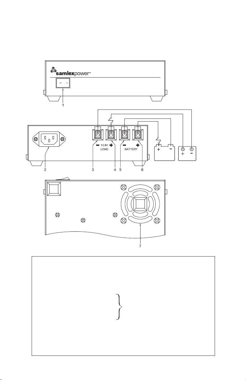
2.1 LAYOUT
SEC-1223BBM-CE
F2
F1
12V BATTERY 12V DC LOAD
BOTTOM VIEW
LEGEND
1. Lighted Power ON /OFF Rocker Switch (Lights Red when ON)
2. AC Power Cord Inlet – Type “IEC 60320-C14” (Detachable Power Cord with
“IEC 60320-C13” connector on one end and CEE-7/7 “Schuko” Plug on the other
end is provided with the unit)
3. Black Negative (-) DC Load Terminal
4. Red Positive (+) DC Load Terminal
5. Black Negative (-) Battery Terminal
6. Red Positive (+) Battery Terminal
7. Vent opening for cooling fan discharge (Bottom of the unit)
F1. Fast blow Fuse: 32V, 25A
F2. Fast blow Fuse: 32V, 25A
*NOTE 1: 5/64” Hex Key and 2 spare set screws have been provided.
Tubular hole Dia 5 mm/0.2” and set screw
(5/64” Hex Socket Head, #10, 24 TPI,
5/16” long)
Fig. 2.1 Layout and Output Connections
See NOTE 1
*
Page 8
SECTION 2 | Layout & Dimensions
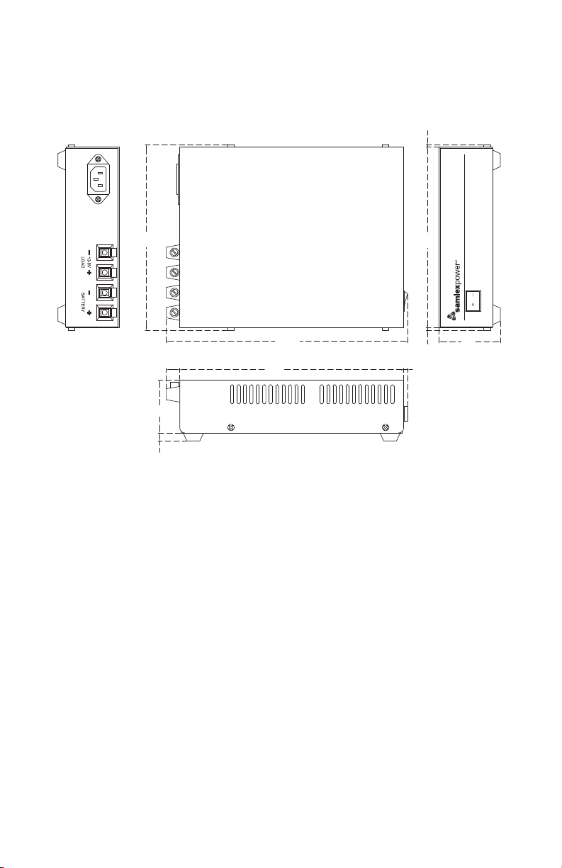
2.2 DIMENSIONS
2.5
SEC-1223BBM-CE
223
TOP VIEW
240.5
180
2.5
4
61
185
13.5
53.3
7.7
Fig 2.2 Dimensional Drawing
SECTION 3 | Description & Principle of Operation
3.1 DESCRIPTION
SEC-1223BBM-CE is a Switch Mode Power Supply (SMPS), which converts 230 VAC,
50/60 Hz to regulated 14.0 VDC at 23A continuous. It has additional provision for battery
backup with charging in conjunction with external 12V Lead Acid Battery. The battery is
oat charged to 13.5 ± 0.2V (when fully charged).
3.2 FEATURES
• Advanced Switch Mode Technology
• Reliable, 12V DC Uninterruptible Power Source (DC UPS) in conjunction with external
12V Lead Acid Battery backup
• Under battery backup function, short time overload of up to 50A for < 1 sec can be
supplied to allow starting of devices that require higher starting surge current.
• High efciency, compact and portable
8 | SAMLEX AMERICA INC.
Page 9

SECTION 3 | Description & Principle of Operation
• Protected against short circuit, overload, over voltage and over temperature
• Cooling by temperature controlled fan improves efciency and prolongs life of the fan
• CE marked for safety and EMI / EMC compliance
3.3 PRINCIPLE OF OPERATION
V
= 0.2 VDC
f
AC Input
230 VAC
L
N
SMPS
SECTION
14 VDC
Fig 3.1 Schematic Diagram - Battery Charging / Backup
Please refer to the schematic diagram at Fig 3.1.
The unit consists of 2 Sections:
a) High efciency Switched Mode Power Supply (SMPS) Section (See details at Section 3.3.1)
b) Battery Charging and Backup Section (See details at Section 3.3.2)
13.8 VDC
R1=1.2Ω
D1
R2=1.2Ω
BATTERY CHARGING AND
BACKUP SECTION
D2
D3
3 4 5 6
F2
12V LOAD
F1
BACKUP
BATTERY
3.3.1 High Efciency Switched Mode Power Supply (SMPS) Section
Refer to Fig 3.1
This Section is a high efciency SMPS that converts 230 VAC, 50/60 Hz to regulated DC
voltage of 14.0V. It uses Switched Mode controller with Pulse Width Modulation (PWM)
Control.
3.3.2 Battery Charging and Backup Section
Refer to Fig 3.1
3.3.2.1 In battery charging and backup application, the SMPS Section (details at Section
3.3.1 above) will supply the load current as well as the battery charging current to keep
the battery charged to Float Voltage of 13.5V± 0.2V as long as AC input to the SMPS
is available and the SMPS is working normally. If the AC input to the SMPS Section
fails or if the SMPS Section itself fails, the battery will act as backup power source and
instantaneously supply power to the load.
3.3.2.2 Regulated 14.0VDC from the SMPS Section (details at Section 3.3.1 above) is fed
to the Battery Charging / Backup Section through Schottky Diode “D1” that provides
isolation between the SMPS Section and the battery to prevent the battery from feeding
back into the SMPS Section. When current passes through a diode, there will be a nonlinear Forward Voltage Drop (Vf) across it. As the power dissipated across the diode will
Page 10

SECTION 3 | Description & Principle of Operation
be equal to Forward Voltage Drop (Vf) multiplied by the diode current, it is desirable
that the Forward Voltage Drop (Vf) has a lower value to reduce power dissipation and
hence, improve efciency. Therefore, “Schottky” type of diode has been used that has
lower Forward Voltage Drop (Vf) of 0.4A at 23A. Schottky Diode “D1” has a non linear
Forward Voltage Drop (Vf) as follows:
TABLE 3.1 FORWARD VOLTAGE DROP (VF) AND VOLTAGE AT CATHODE OF
SCHOTTKY DIODE “D1” (FIG 3.1)
Diode “D1”
(Column 1)
Forward Voltage Drop
(Vf) for Diode “D1”
Voltage at Cathode
of Diode “D1”
(14.0V – Vf)
It will be seen from Table 3.1 above that the Forward Voltage Drop (Vf) of Schottky
Diodes “D1” ” varies from 0V at 0A (no load) to 0.4V at 23A. Hence, the voltage at the
Cathode of Schottky Diode “D1” will be = 14.0VDC – Forward Voltage Drop across “D1”
and will range from 14.0 V to 13.6V (or say 13.8 ± 0.2V).
3.3.2.3 14.0V to 13.6V (or say 13.8 ± 0.2V) from the Cathode of Schottky Diode “D1” is
fed to 2 branches as follows:
a) Branch 1 for DC Load: To the Positive Load Terminal (4, Fig 3.1) directly
b) Branch 2 for Battery Charging and Backup: To the Battery Positive Terminal (6
in Fig 3.1) through 2 x 1.2 Ohm parallel connected resistances R1 and R2 (2 x 1.2
Ohm parallel connected resistances will present effective series resistance of 1.2
Ohm ÷ 2= 0.6 Ohm). The battery charging current will be determined by the
following approximate equation:
Charging
Current
= [Voltage at Cathode of Diode “D1” – Voltage at the Battery Terminals] ÷ 0.6 Ohm …Equation 1
current = 0A
(Column 2)
0V 0.25V 0.4V
14V 13.75V 13.6V
Diode “D1”
current =0.1 to 5A
(Column 3)
Diode “D1” Current
= 19 to 23 A
(Column 4)
3.3.2.4 Using Equation 1 above, it will be seen that the effective series resistance of
0.6 Ohm will limit the charging current. The charging current will be higher when the
battery is more discharged and will progressively reduce as the battery voltage rises
when charged. The rated charging current of 4A is based on the unit supplying 19A to
load and at the same time, charging a typical 100 Ampere Hour (Ah) battery discharged
to 11.1V (70% discharged at Discharge Rate of 23A i.e. at around 5 Hr Discharge Rate of
C/5). When the battery is charged to Float Voltage of 13.5V± 0.2V, the charging current
will reduce to a very low value of around 0.1% of its Ampere Hour (Ah) capacity to
compensate for its self discharge. For example, assuming that 100Ah capacity battery
is being used, the Float Charging Current will be 0.1% of 100Ah or, 0.1A. Therefore,
applying Equation 1 at Section 3.3.2.3 above, the voltage at the Battery Terminals
(5, 6 in Fig and 3.1) will be as given in Tables 3.2.1 and 3.2.2:
10 | SAMLEX AMERICA INC.
Page 11

SECTION 3 | Description & Principle of Operation
TABLE 3.2.1 CHARGING VOLTAGE AT BATTERY TERMINALS – LOAD CURRENT 0A
• Load Current = 0A
• Float Charging Current = 0.1A
• Total SMPS Current = 0.1A
• Load Current = 0A
• Full Charging Current = 4.0A
• Total SMPS Current = 4.1A
Column (1)
Voltage at Battery
Terminals based
on Equation 1
(Section 3.3.2.3)
TABLE 3.2.2 CHARGING VOLTAGE AT BATTERY TERMINALS – LOAD CURRENT 19A
Column (1)
Voltage at Battery
Terminals based
on Equation 1
(Section 3.3.2.3)
3.3.2.5 When the AC input to the SMPS Section fails or if the SMPS itself fails, the
battery will provide backup power to the load instantaneously through Schottky Diode
“D2”. Please note that current from the battery to the load will NOT pass through
Resistors R1 and R2 because Schottky Diode “D2” will bypass these resistors due to its
lower resistance.
3.3.2.5.1 Current ow through Schottky Diode “D2” will produce non-liner Forward
Voltage Drop (Vf) as given in Table 3.3 below:
TABLE 3.3 FORWARD VOLTAGE DROP (VF) OF SCHOTTKY DIODES “D2”
(Column 1)
Forward Voltage
Drop (Vf) for Diode
“D2”
Voltage at Cathode
of Diode “D2”
13.75V * – (0.1A x 0.6 Ohm) =
13.69V
*Based on Table 3.1, Column (3)
• Load Current = 19A
• Charging Current = 4.0A
• Total SMPS Current = 23A
13.6V** – (4.0A x 0.6 Ohm) =
11.2V
**Based on Table 3.1, Column (4)
Diode “D2” Current
Battery Voltage – 0V Battery Voltage – 0.25V Battery Voltage – 0.4V
Column (2)
13.75V * – (4.0A x 0.6 Ohm) =
11.35V
*Based on Table 3.1, Column (3)
• Load Current = 19A
• Charging Current = 0.1A
• Total SMPS Current = 19.1A
Column (2)
13.6V** – (0.1A x 0.6 Ohm) =
13.54V
**Based on Table 3.1, Column (4)
= 0A
(Column 2)
0V 0.25V 0.4V
Diode “D2” Current
= 0.1A
(Column 3)
Column (3)
Column (3)
Diode “D2” Current
= 19 to 23A
(Column 4)
Page 12

SECTION 3 | Description & Principle of Operation
3.3.2.6.1 The voltage available at the Load Terminals (3,4 in Figs 2.1 and 3.1) during
battery backup will be as per Equation 2 below:
Voltage at Load Terminals when battery is
supplying the load
Battery Voltage – Forward
=
Voltage Drop across
Schottky Diode “D2”
...Equation 2
3.3.2.6.2 Examples of voltages at the Battery Terminals (5, 6 in Fig 3.1) at different
states of charge / discharge are given at Table 3.4 below:
TABLE 3.4 VOLTAGE AT BATTERY TERMINALS WHEN AC INPUT POWER HAS FAILED
AND THE BATTERY IS SUPPLYING THE LOAD
• Load current = 19A
• Load current = 19A
• Battery voltage at Floating
Voltage of 13.55V
• Battery voltage of say 11.4V
at 80% discharged state based
on 100Ah capacity discharging
at 5 Hr Discharge Rate of C/5
Column (1)
Column (2)
Column (3)
Voltage at battery
terminals (5, 6
in Fig 3.1) when
AC input power
has failed and
the battery is
13.54V* – 0.4**V = 13.14V
*Based on Table 3.2.2, Column (3)
** Based on Table 3.3, Column (4)
11.4V – 0.4*V = 11.0V
* Based on Table 3.3, Column (4)
supplying the load
[Based Equation 2
(Section 3.3.2.6.1)]
3.3.3 Output Voltage Adjustment at No Load
The no load output voltage is factory preset at 14.0V (13.8VDC ± 0.2V) at both the Load
and Battery Terminals. Potentiometer marked “VR1” is provided in the SMPS Circuit
Board for no load output voltage adjustment range of 10.8 VDC to 16.2 VDC.
3.3.4 Normal Power Supply Function when Battery Backup is not used
If battery backup function is not used (external backup battery is not connected), the
unit will work as a normal power supply with ability to supply 23A continuous at 13.8 ±
0.2 V at the Load Terminals (3, 4 in Figs 3.1 and 2.1).
3.4 COOLING AND OVER TEMPERATURE PROTECTION
The unit is cooled by convection and in addition, has a temperature-controlled fan
located at the bottom for forced air-cooling. Two Normally Closed Thermal Switches are
mounted on the windings of the Switching Power Transformer – one for fan control and
the other for over temperature shut down. When the temperature of the transformer
windings rises to ≥ 60°C ± 5°C / 140°F ± 9°F, Thermal Switch for fan control will open
and will activate fan switching circuit to switch ON the fan. When the transformer
windings cool down to ≤ 40°C ± 5°C / 104°F ± 9°F, the switch will close and de-activate
fan switching circuit to switch OFF the fan.
12 | SAMLEX AMERICA INC.
Page 13
!
!
SECTION 3 | Description & Principle of Operation
NOTE: The fan may not switch ON at all in case of low loads or in colder ambient
temperatures because the temperature of the transformer windings may not rise to
threshold of ≥ 60°C ± 5°C / 140°F ± 9°F under these conditions.
In case the fan fails or if the cooling is not adequate due to higher ambient temperature,
inadequate air circulation or blockage of ventilation openings, the temperature of the
transformer windings will rise. At temperature ≥ 105°C ± 5°C / 221°F ± 9°F, Thermal Switch for
over temperature shut down will open and will activate over-temperature protection circuit
to shut down the Power Supply Section. When the windings cool down to temperature ≤ 75°C
± 5°C / 167°F ± 9°F, the switch will close, shut down circuit will be de-activated and the output
power from the Power Supply Section will be restored automatically. During the time the
Power Supply Section is shut down due to over temperature, the backup battery will supply
the load and will start discharging. When the Power Supply Section cools down and resets, it
will once again start supplying the load and re-charge the battery.
CAUTION!
The fan draws cool air from the vent openings on the sides of the unit and
discharges hot air through vent openings at the bottom of the unit. PLEASE
ENSURE THAT THESE VENT OPENINGS ARE NOT OBSTRUCTED.
ATTENTION!
Le ventilateur aspire l’air froid de l’ouvertures de ventilation sur les côtés
de l’unité et les rejets d’air chaud par les ouvertures d’aération au bas de
l’unité. VEUILLEZ VOUS ASSURER QUE CES OUVERTURES DE VENTILATION
NE SONT PAS OBSTRUÉES.
Page 14

SECTION 4 | Protections
4.1 OVER LOAD / SHORT CIRCUIT CURRENT PROTECTIONS
4.1.1 Battery Backup Function is not Used - External Battery is not Connected
and the Unit is Used as a Power Supply
In this case, the entire load current will be supplied by the Power Supply Section and will
be limited to a maximum of 25A by its Current Limit Circuitry. If the load tries to draw
a higher current than the current limit value of 25A, the output voltage at the Load
Terminals (3, 4 in Fig 2.1) and the Battery Terminals (5, 6 in Fig 2.1) will not be regulated
and will drop below 13.8V± 0.2V. If the load impedance is further reduced, the current will
remain limited at 25A but the voltage will drop further. In case of short circuit, maximum
limited current of 25A will continue to be supplied into the short circuit but the voltage
will drop to < 2V in case of a near dead short (Load impedance will be very low – say
< 100 milli Ohm). If over-load / short-circuit current of 25A continues over prolonged
period (> 100 sec), the external 25A load side Fuse (F2, in Fig 2.1) will blow and will
disconnect the load. If the overload / short circuit is removed before the external 25A
load side Fuse (F2, in Fig 2.1) blows, the output voltage at the Load / Battery Terminals
will automatically recover when the load current drops to less than 25A.
4.1.2 Battery Backup Function is Used - External Battery is Connected
If the load tries to draw current higher than the current limit value of 25A of the Power
Supply Section, the output voltage of the Power Supply Section will not be regulated and the
voltage at the Load Terminals (3, 4, Fig 2.1) will drop. Portion of overload current beyond 25A
will now be fed from the battery and the battery will start draining at this differential current.
For example, if the overload current was 40A, the Power Supply Section will provide 25A and
the battery will provide the balance 15A. The battery will start draining at 15A. The voltage
at the Battery Terminals (5, 6, Fig 2.1) will start dropping and will be equal to the voltage
corresponding to its actual State of Charge. The voltage at the Load Terminals (3, 4 in Fig 2.1)
will be up to 0.4 VDC below the voltage at the Battery Terminals (5, 6 in Fig 2.1) because of
forward voltage drop across diode D2 (Fig 3.2). This drop will depend on the current being
supplied through this diode (TABLE 3.3). External 25A Fuse (F2, Fig 2.1) on the load side will
blow only on sustained current ≥ 25A for > 100 sec but will not blow at higher short duration
surge currents determined by its Time Current characteristics. For example, based on the Time
Current Characteristics of 32V, 25A fuse Type ATC-25 from Cooper Bussmann, the fuse can pass
extremely high currents for shorter durations is as follows:
• 550A for 10 ms
• 170A for 100 ms
• 40A for 1 sec
• 25A continuous (for > 100 sec)
In case of short circuit on the load side, the external 25A Fuse (F2) on the load side will
blow because of very high additional current supplied by the battery (Additional battery
current supplied into the short circuit on the load side = Short circuit current - 25A from
the Power Supply Section). For example, if a short circuit current of 170A tries to ow
for > 100 ms, 25A will be supplied by the Power Supply Section and the balance 145A
will be supplied by the battery. As the external 25A Fuse (F2, Fig 2.1) on the load side
will see 170A and the external 25A Fuse (F1, Fig 2.1) on the battery side will see 145A,
the external 25A load side Fuse (F2, Fig 2.1) will blow rst.
14 | SAMLEX AMERICA INC.
Page 15
SECTION 4 | Protections
!
!
!
!
4.2 PROTECTION AGAINST REVERSE POLARITY OF BATTERY CONNECTION
In case of reverse polarity of battery connection, internal Diode connected across the
battery output terminals (D3, Fig 3.1) will be forward biased and the external 32V, 25A
battery side Fuse (F1, Fig 2.1) will blow.
CAUTION!
Reversal of polarity may result in permanent damage to the unit and to the load.
DAMAGE DUE TO REVERSE POLARITY IS NOT COVERED UNDER WARRANTY.
ATTENTION!
Inversion de polarité peut causer des dommages permanents à l’unité et
à la charge. LES DOMMAGES DUS À L’INVERSION DE POLARITÉ N’EST PAS
COUVERT PAR LA GARANTIE.
4.3 OVER TEMPERATURE PROTECTION
CAUTION!
Keep the unit in a well-ventilated, cool and open area. DO NOT block the vent
holes on the sides or the discharge openings of the cooling fan at the bottom
of the unit.
ATTENTION!
La placer dans un endroit bien aéré, frais et ouvert. N’obstruez pas les orices
de ventilation sur les côtés ou les ouvertures de décharge du ventilateur de
refroidissement au bas de l’unité.
In case the fan fails or if cooling is not adequate due to higher ambient temperature
or inadequate air circulation or blockage of air ventilation openings, the temperature
of the output power transformer windings will rise and at temperature ≥ 105°C ± 5°C
/ 221°F ± 9°F, Thermal Switch mounted on the windings will open and will activate
over-temperature protection circuit to shut down the Power Supply Section. When the
windings cool down to temperature ≤ 75°C ± 5°C / 167°F ± 9°F, the Switch will close, shut
down circuit will be de-activated and the Power Supply Section will be reset automatically. During the time the Power Supply Section is shut down due to over temperature,
the backup battery will supply the load and will start discharging. When the Power
Supply Section cools down and resets, it will once again start supplying the load and
re-charge the battery.
4.4 OVER VOLTAGE PROTECTION
Over voltage protection is provided through the internal PWM controller.
Page 16
SECTION 5 | Installation
5.1
!
5.2 INSTALLATION DIMENSIONS
Refer to Section 2, Figs 2.2 for installation dimensions.
5.3 LOCATION OF INSTALLATION
Please ensure that the following requirements are met:
WARNING!
a) Before commencing installation, please read the safety instructions explained
in Section 1.
b) It is recommended that the installation should be undertaken by a qualied,
licensed / certied electrician.
c) Various recommendations made in this manual on installation will be super-
seded by the National / Local Electrical Codes related to the location of the
unit and the specic application.
MISE EN GARDE!
a) Avant de commencer l’installation, veuillez lire les consignes de sécurité
décrites dans la section 1.
b) Il est recommandé que l’installation doit être effectuée par un technicien
qualié, autorisé / électricien certié.
c) Différentes recommandations faites dans ce manuel sur l’installation
sera remplacée par la National / les codes électriques locaux liés à
l’emplacement de l’unité et l’application spécique.
Working Environment: Indoor use.
Cool: Heat is the worst enemy of electronic equipment. Hence, please ensure that the
units are installed in a cool area that is also protected against heating effects of direct
exposure to the sun or to the heat generated by other adjacent heat generating devices.
Well ventilated: The unit is cooled by convection and by forced air-cooling by temperature
controlled fan on the bottom of the unit. The fan at the bottom of the unit draws cool
air from air intake openings on the sides and discharges hot air through the exhaust
openings under the fan. To avoid shut down of the unit due to over temperature, do
not cover or block the ventilation / suction / exhaust openings or install the unit in an
area with limited airow. Keep a minimum clearance of 10” around the unit to provide
adequate ventilation. If installed in an enclosure, openings must be provided in the
enclosure, directly opposite to the air-suction and air-exhaust openings of the unit.
Dry: There should be no risk of condensation, water or any other liquid that can enter
or fall on the units.
16 | SAMLEX AMERICA INC.
Page 17

SECTION 5 | Installation
Clean: The area should be free of dust and fumes. Ensure that there are no insects or
rodents. They may enter the units and block the ventilation openings or short circuit
electrical circuits inside the units.
Protection against re hazard: The unit is not ignition protected and should not be
located under any circumstance in an area that contains highly ammable liquids like
gasoline or propane as in an engine compartment with gasoline-fueled engines. Do not
keep any ammable / combustible material (i.e., paper, cloth, plastic, etc.) near the unit
that may be ignited by heat, sparks or ames.
Accessibility: Do not block access to the front panel. Also, allow enough room to access
the AC inlet and the DC wiring terminals and connections at the back of the unit, as
they will need to be checked and tightened periodically.
Preventing Radio Frequency Interference (RFI): The unit uses high power switching
circuits that generate RFI. This RFI is limited to the required standards for EMI / EMC
for CE marking. Locate any electronic equipment susceptible to radio frequency and
electromagnetic interference as far away from the unit as possible. For additional
information, please read Section 7 titled “Limiting Electromagnetic Interference (EMI)”.
5.4 MOUNTING ORIENTATION
The unit has air intake openings on the sides and exhaust openings at the bottom for
the cooling fan. The unit should be mounted in such a manner so that small objects
should not be able to fall easily into the unit from these openings and cause electrical /
mechanical damage. Also, the mounting orientation should be such that if the internal
components overheat and melt / dislodge due to a catastrophic failure, the melted /
hot dislodged portions should not be able to fall out of the unit on to a combustible
material and cause a re hazard. The size of openings has been limited as per the
safety requirements to prevent the above possibilities when the unit is mounted in the
recommended orientations. In order to meet the regulatory safety requirements, the
mounting has to satisfy the following requirements:
- Mount on a non-combustible material.
- The mounting surface should be able to support the weight of the unit
- Mount horizontally on a horizontal surface (e.g. table top or a shelf).
- Mounting horizontally on a vertical surface – The unit can be mounted on a vertical
surface (like a wall) with the DC output terminals either facing up or down.
!
WARNING!
Mounting the unit on a vertical surface with the ventilation slots on the sides
facing up / down is NOT recommended. As explained above, this is to prevent
(i) falling of objects into the unit through the slots causing short circuit or (ii)
falling out of dislodged overheated / melted components on to a combustible
material in case of catastrophic internal failure.
Page 18

SECTION 5 | Installation
MISE EN GARDE!
Montage de l’appareil sur une surface verticale avec les fentes de ventilation
sur les côtés vers le haut / vers le bas n’est pas recommandé. Comme
expliqué ci-dessus, il s’agit d’éviter que (i) la chute d’objets dans l’unité à
travers les fentes provoquant un court-circuit ou (ii) en tombant de délogé
/ composants surchauffés fondu sur un matériau combustible en cas de
défaillance interne catastrophique.
5.5 AC SIDE CONNECTION
230 VAC power is fed to the unit through detachable, 230 VAC power cord supplied
with the unit. The power cord has the following specications:
• Length of the cord: 6 ft
• Cable : 3 conductors (Line – Brown; Neutral – Blue; Protective Earth – Green /
Yellow), each 0.75 mm
• 10A, 250V connector for power supply end: “IEC 60320 – C13” female connector
[Insert this end into the AC Power Inlet on the unit (2, Figs 2.1)]
• 16A, 250V CEE-7/7 “Schuko” Plug for connecting to 230 VAC “Schuko” outlet
2
/ AWG #18
5.6 DC OUTPUT TERMINALS
5.6.1 DC Output Terminals: DC output is provided as follows:
• Red Positive Terminal for Load (4, Figs 2.1) and for Battery (6, Fig 2.1):
o Tubular Hole – Diameter 5 mm / 0.2”
o *Set Screw: 5/64” Hex Socket Head Screw; #10, 24 TPI, 5/16” long
• Black Negative Terminal for Load (3, Figs 2.1) and for Battery (5, Fig 2.1):
o Tubular Hole – Diameter 5 mm / 0.2”
o *Set Screw: Hex 5/64” Socket Head screw; #10, 24 TPI, 5/16” long
*NOTE: The following have been provided for convenience:
a) 5/64” Hex / Allen Key for the Hex Socket Head Screw.
RETAIN THE HEX / ALLEN KEY FOR FUTURE USE
b) 2 spare Hex socket head screws
5.6.2 Pin Type of Terminal Lugs for Wiring to be Connected to DC Output Terminals:
The DC output terminals have a tubular hole with a set screw (See Section 5.6.1 above for
specications). As the DC terminals have been provided with a set screw, do not connect
bare stranded wire end directly to the DC output terminal as the strands will spread out
when the set screw is tightened and all the strands may not be pinched rmly under
the set screw. This will result in (i) reduction in effective area of cross section for current
conduction leading to increased voltage drop and overheating along output wiring and
(ii) sparking / loose connection under the set screw leading to overheating / melting of
the plastic material of the terminals. The ends of stranded wiring to be connected to
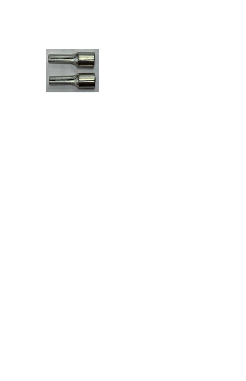
the DC output terminals should be crimped to Pin Type of Terminal Lugs that have been
provided with the unit (see Fig 5.1). After crimping the Terminal Lugs, use insulating heat
shrink tubing or tape to insulate the bare cylindrical portion of the lugs.
18 | SAMLEX AMERICA INC.
Page 19
SECTION 5 | Installation
Manufacturer: K.S. Terminals
Part No. : PTNB10-12
Wire gauge: Up to AWG #8 (10 mm
Fig 5.1 Pin type of terminal lugs provided for termination of
stranded wiring to be connected to the DC input terminals.
5.7 DC OUTPUT CONNECTIONS
Load Connection: The load is connected to the terminals marked “Load +” (4, Fig 2.1)
and “Load - ” (3, Fig 2.1) through 32V, 25A Fuse (F2, Fig 2.1) (See details below under
heading “External Fuses”). Please ensure that the polarity of the connection is correct Positive of the load to the “Load +” terminal (4, Fig 2.1) and the Negative of the load to
the “Load - ” terminal (3, Fig 2.1).
Battery Connection: The Positive of the battery is connected to the “Battery +” terminal
(6, Fig 2.1) and the Negative of the battery to the “Battery - ” terminal (5, Fig 2.1) through
32V, 25A Fuse (F1, Fig 2.1) [Refer to Section 5.9 for details].
Recommended Battery Capacity: Battery should not be charged at very high current.
Normally, as a Rule of Thumb, the maximum charging current should be limited to 10%
of the Ah capacity at 20 Hour Rate unless higher current is allowed by the manufacturer.
Higher charging current produces higher heating which reduces the life of the battery.
Further, higher charging current will not re-charge the battery to full 100% capacity
unless the charging voltage is increased proportionately. It is recommended that the
capacity of the battery used with this unit should be in the range of 40 to 100Ah.
5.8 DC OUTPUT WIRE SIZING
Use AWG #10, 90°C / 194°F insulation wire for the load and battery connections for a
distance of up to 3 ft. Thicker wire will be required for distance longer than 3 ft. (See
Table 5.1). USE THICKER WIRE OUT THE 2 SIZES CALCULATED BASED ON THE FOLLOW-
ING 2 CONSIDERATIONS:
2
)
5.8.1 Safety of Conductor Insulation
Current (I) owing through resistance (R) of conductor produces power loss (I
the form of heat which results in temperature rise in the conductor. Temperature rise
is higher for higher current, higher resistance (longer length and thinner cross section
produce higher resistance) and higher ambient temperature. Temperature rise higher
than the temperature rating of conductor insulation will melt / burn the insulation
resulting in possibility of electrical shock and re. The National Electrical Code species
maximum current ow (Ampacity) through a particular wire size [normally specied
as cross-section in American Wire Gauge (AWG)] for a particular temperature rating of
conductor insulation, ambient temperature and type of surrounding medium (like free
2
R) in
Page 20

SECTION 5 | Installation
air, raceway, etc.). NEC further species that the Ampacity of the wire should be 1.25
times the maximum current ow. The maximum output current in the unit is 25A.
- The maximum output current in the unit is 25A. Hence, the Ampacity of the
wires as per NEC should 1.25 x 25 = 31.25A or say 40A
- As per NEC Table 310.15(B)(17) for 90°C / 194°F conductor insulation, free air,
40°C / 104°F ambient and Ampacity of 40A, the minimum conductor size should
be AWG #10.
5.8.2 Limiting Voltage Drop along the Length of the Wiring
Current owing through resistance produces voltage drop. Voltage drop is higher
for higher resistance (longer length and thinner cross section produce higher resistance).
Excessive voltage drop across the length of wires connecting the power source to the
load produces excessive power loss and may also shut down the load due to under
voltage created at the load end. Hence, the voltage drop should be kept to the
minimum at around 2% by using thicker wires for longer distances. Table 5.1 given
below shows thickness of wire for 2% voltage drop consideration for 12 V battery / load
when carrying 25A:
TABLE 5.1: RECOMMENDED WIRE SIZES FOR 3 FT., 6FT. AND 10 FT. DISTANCES
Size of Wiring for 2% Voltage Drop
Rated Current
25A AWG #10 AWG #8 AWG #6
3 ft. 6 ft. 10 ft.
As mentioned above, the calculated wire size is AWG #10 when considering safety of
conductor insulation. Hence, use AWG #10, 90°C / 194°F insulation wire for the load and
battery connections for a distance of up to 3 ft. If the distance of the Load / Battery is >
3 ft., the size on account of 2% voltage drop and 25A current ow consideration will be
thicker than AWG #10 as shown in Table 5.1 above and these thicker sizes should be used.
5.9 EXTERNAL FUSES ON THE BATTERY AND LOAD SIDES
A battery is an unlimited source of current that can drive thousands of Amperes of current into a short circuit leading to overheating and burning of wiring / circuit components along the path from the battery terminals to the point of short circuit. This can
cause injury and is a re hazard. Similarly, a power source is also be capable of driving
considerably high value of current into a short circuit on the load side and causing
damage as above (the current will, however, be limited to the maximum rated overload
current and not unlimited as in the case of a battery). Appropriate fuse should, therefore, be used in series with the battery Positive post / Load terminal of power source to
protect against the above safety hazard. FOR EFFECTIVE PROTECTION, APPROPRIATE
SIZES OF FUSES SHOULD BE LOCATED AS FOLLOWS:
• External Battery Side Fuse (F1, Fig 2.1) should be LOCATED as close to the battery
Positive post as possible, preferably within 7” of the battery Positive post.
• External Load Side Fuse (F2, Fig 2.1) should be installed as close as possible to the
Positive Load Terminal (4, Fig 2.1).
20 | SAMLEX AMERICA INC.
Page 21

!
SECTION 5 | Installation
For this unit, external fuses must be used for protection against reverse polarity and
short circuit as follows:
• 32V, 25A fast acting Fuse (F1, Fig 2.1) in series with the Positive battery wire within 7”
from the battery Positive post. This fuse provides the following protections:
- Prevents overheating and burning of wiring due to very heavy current fed from
the battery into a short circuit along the length of wiring from the battery to the
Battery Input Terminals (5, 6 in Fig 2.1).
- Prevents damage to the unit and to the load due to reverse polarity of battery
connection
• 32V, 25A fast acting Fuse (F2, Fig 2.1) in series with the Positive load wire and within
7” of the Positive Load Terminal (4, Fig 2.1). This fuse protects against overload and
short circuit on the load side.
SECTION 6 | Operation
6.1
CAUTION!
If AC input power is not available and a battery has been connected for
backup function, the load will be powered by the battery and the battery will
continue to discharge as long as the load is in ON condition. When the load is
not delivering power, it still draws current for its self-consumption (called "No
Load Current"). When AC input power is not available, switch OFF the load
if not required, otherwise the battery will get discharged because of the "No
Load Current" drawn by the load.
MISE EN GARDE!
Si l’alimentation d’entrée n’est pas disponible et d’une batterie a été connecté
pour la fonction de sauvegarde, la charge va être alimenté par la batterie
et la batterie va continuer à s’acquitter tant que la charge est dans l’état.
Lorsque la charge n’est pas offrant puissance, il attire encore courant pour son
auto-consommation (appelé “Pas de charge”). Lorsque l’alimentation d’entrée
n’est pas disponible, couper la charge si pas nécessaire, sinon la batterie sera
déchargée car des “Pas de charge” dessiné par la charge.
Page 22

SECTION 6 | Operation
6.2 SWITCHING ON / OFF
6.2.1 Switching ON (Without Battery Backup - No External Battery - Unit
Operates as a Normal Power Supply):
- Check that the load has been connected to the Load Terminals (3, 4 in Fig 2.1)
and NOT TO THE BATTERY TERMINALS (5, 6 in Fig 2.1)
- Switch ON the unit with the help of the Red Power ON / OFF Switch (1, Fig 2.1). If
AC power is available and the internal AC side fuse is intact, the ON / OFF Switch
will be lighted Red indicating that the Power Supply Section is in ON condition
- After a few milli sec, 13.8V ± 0.2V will be available at the Load and Battery Terminals
- Switch ON the load
6.2.2 Switching ON (With Battery Backup - External Battery is Connected):
- Check that the load has been connected to the Load Terminals (3, 4 in Fig 2.1)
through external 25A Load Side Fuse (F2, Fig 2.1)
- Check that the external battery has been connected to the Battery Terminals (5,
6 in Fig 2.1) through external 25A Battery Side Fuse (F1, Fig 2.1)
- Switch ON the unit with the help of the Red Power ON / OFF Switch (1, Fig 2.1).
If AC power is available and the internal AC side fuse is intact, the ON / OFF
Switch will be lighted Red indicating that the Power Supply Section is in ON
condition
- After a few milli sec, 13.8V ± 0.2V will be available at the Load Terminals (3, 4
in Fig 2.1) and the external battery will start charging at current of up to 4A
determined by its State of Charge. The voltage at the Battery Terminals (5,6) will
get clamped to the actual terminal voltage of the battery corresponding to its
State of Charge
- Switch ON the load
- The Power Supply Section will supply all the current consumed by the load and
the external battery will be maintained in charged condition all the time at
Float Voltage of 13.5V ± 0.2V (when fully charged)
6.2.3 Switching OFF:
- Switch OFF the load rst
- Switch OFF the unit with the help of the Red Power ON / OFF Switch (1, Fig 2.1).
Red light inside the ON /OFF switch will switch OFF
6.3 CHARGING AND BACKUP OPERATION
Charging current will be proportional to the discharged state of the battery and is
limited to maximum of 4A when the battery is completely discharged (Standing Voltage
of 11.1V). The current will taper down from 4A as the battery gets charged and its
voltage rises. When the battery is fully charged, the current will drop down to 0.1% of
the Ah capacity of the battery to compensate for self-discharge. When fully charged, the
voltage at the Battery Terminals (5, 6) will be the Float Voltage of 13.5V ± 0.2V.
22 | SAMLEX AMERICA INC.
Page 23

SECTION 6 | Operation
Battery should not be charged at very high current. Normally, as a Rule of Thumb, the
maximum charging current should be limited to 10% of the Ah capacity at 20 Hour Rate
unless higher current is allowed by the manufacturer. Higher charging current produces
higher heating, which reduces the life of the battery. Further, higher charging current will
not re-charge the battery to full 100% capacity unless the Absorption Voltage is increased
proportionately. This may not be possible with chargers that do not have programmable
charging voltages. It is, therefore, recommended that the capacity of the battery used with
this unit should be in the range of 40 to 100Ah which is appropriate for 4A charging current.
The voltage seen at the Battery Terminals (5, 6 in Fig 2.1) will be the actual terminal
voltage of the battery (assuming no voltage drop in the battery cables) and will be
proportional to its State of Charge. When the battery is fully charged, the voltage at the
Battery Terminals (5, 6 in Fig 2.1) will approach 13.5V ± 0.2V.
If AC input power fails, the DC load(s) will be instantaneously transferred to the external
12V backup battery and the battery will start discharging. When the battery is supplying
the load, the voltage seen at the Load Terminals will be up to 0.4 VDC less than the
voltage at the Battery Terminals (5,6 in Fig 2.1) due to forward voltage drop across diode
D2 (Fig 3.2). This drop will depend upon the current being supplied through this diode
(TABLE 3.3). When AC input power is restored, the DC load will once again be transferred
instantaneously to the Power Supply Section and the external backup battery will be
recharged and kept in charged condition all the time at Float Voltage of 13.5V ± 0.2V
(when fully charged).
6.4 SURGE POWER CAPABILITY IN DC UPS BATTERY BACKUP MODE
When operating in DC UPS Battery Backup Mode (external 12V battery is connected),
the unit is capable of providing short term surge current of up to 50A for < 1 sec
(external 25A fuse on the load side will not blow for this short duration). Maximum 25A
will be provided by the Power Supply Section and balance 25A will be supplied by the
battery. During the period of this short term overload, the voltage seen by the load will
be = (battery voltage – 0.3V± 0.2V).
6.5 OPERATION AS NORMAL POWER SUPPLY WITHOUT EXTERNAL BATTERY
If battery backup function is not used (external backup battery is not connected), the
unit will work as a normal power supply with ability to supply 23A continuous at 13.8V
± 0.2VDC at the Load Terminals (3, 4 in Fig 2.1). The maximum overload current will be
limited to 25A. Under overload conditions, the output voltage will not be regulated and
will drop.
Page 24

!
SECTION 7 | Limiting Electro-Magnetic
Interference (EMI)
7.1
CAUTION!
Conducted and radiated noises in this unit are limited as per the applicable
National / International Standards. In North America, the applicable standard
is FCC Part 15(B) for Class “B” Digital Devices for Residential Installations. The
corresponding European standard is EN55022, Class “B” & EN610000-3-2, 3.
This unit generates, uses and can radiate radio frequency energy and, if not
installed and used in accordance with the instructions, may cause harmful
interference to radio communications. However, this does not guarantee that
interference will not occur in a particular installation. If this equipment does
cause harmful interference to radio or television reception, which can be
determined by turning the equipment off and on, the user is encouraged to
try to correct the interference by one or more of the measures recommended
in the following paragraphs.
MISE EN GARDE!
Bruits et rayonnement dans cette unité sont limitées que par la législation
nationale / normes internationales. En Amérique du Nord, la norme
applicable est FCC Partie 15(B) pour la classe “B” des appareils numériques
pour les installations résidentielles. La norme européenne correspondante est
EN55022, Classe “B” & ; EN610000-3-2, 3.
Cet appareil génère, utilise et peut émettre une énergie de fréquence radio et,
s’il n’est pas installé et utilisé conformément aux instructions, peut causer des
interférences nuisibles aux communications radio. Cependant, cela ne garantit
pas qu’aucune interférence ne se produira dans une installation particulière.
Si cet équipement provoque des interférences nuisibles à la réception radio ou
télévision, ce qui peut être déterminé en éteignant l’équipement, l’utilisateur
est encouragé à essayer de corriger les interférences en prenant une ou
plusieurs des mesures recommandées dans les paragraphes suivants.
7.2 UN-INTENTIONAL RF NOISE GENERATED BY SWITCHED MODE
POWER SUPPLIES (SMPS)
Switched Mode Power Supplies (SMPS) employ high frequency switching (25 KHz in this
unit) and thus, are a source of radio interference, a recipient of radio interference and a
conduit of radio interference. (Older Linear Type, low frequency 50 / 60 Hz transformer
based power supplies do not employ high frequency switching voltages and will be
quieter as compared to SMPS).
The primary emission sources originate in the switching devices due to their fast switching current transitions: harmonics of the switching frequency and broadband noise
created by under-damped oscillations in the switching circuit. The secondary source is
24 | SAMLEX AMERICA INC.
Page 25

SECTION 7 | Limiting Electro-Magnetic
Interference (EMI)
from the bridge rectier, both rectier noise and diode recovery. The AC input rectier
/ capacitor in the front end of the SMPS (excepting those with Power Factor correction)
generate power supply harmonics due to the non-linear input current waveform. The
noise is both conducted and radiated through the input power cord and the DC output
wiring to the radio.
7.3 FILTRATION OF CONDUCTED NOISE
The conducted RF noise from this SMPS unit is limited to the maximum allowable
levels by internal ltration. The ltered RF noise currents (< few hundred micro Amps)
are bypassed to the chassis of the power supply. The chassis is, in turn, connected to
the Earth Ground pin of the AC input power cord (for Class 1 units). Thus, the ltered
noise currents are intentionally leaked to the Earth Ground. This is termed as the “Earth
Leakage Current”.
7.4 EXCESSIVE RF OUTPUT INTERFERENCE BY SMPS DUE TO
INCOMING RF INTERFERENCE WHEN POWERING RADIO TX / RX
SMPS are also recipients of radio interference. The normal operation of the power supply can be disturbed due to RF noise getting coupled into the power supply. Thus, the
power supply may generate excessive RF noise and lose output voltage regulation due
to excessive transmitter energy being coupled through the AC / DC lines to the power
supply’s regulator feedback path. This may be due to antenna being too close or due to
the antenna or feed system not radiating properly. First, check the antenna system SWR.
Then, if necessary, relocate either the antenna or the power supply farther apart. The
receiver may “hear” the power supply. A slowly moving, slightly buzzing carrier heard
in the receiver may be caused by the antenna being too close. As with the transmitter
related noise pick up, a loose coaxial connector or a broken or a missing ground may
aggravate this problem. Normally, this noise will be below the background or “band”
noise. Increase the separation between the power supply and the receiving antenna.
Use an outdoor antenna. This will reduce the amount of signal picked up from the
power supply and also increase the amount of the desired signal.
7.5 ADDITIONAL GUIDELINES FOR REDUCING RF NOISE
• Use additional appropriate AC Radio Frequency Interference (RFI) Power Line Filter
rated for minimum 10A immediately before the AC input of the power supply. .
Filtered, Ferrite Coated Cord Set is another choice. These cord sets, with integral line
interference lters, reduce Common and Differential Mode Interferences over a wide
frequency range. Because they are shielded, they are also effective against radiated
interferences. In addition to the built-in lter networks, the cable conductors are
coated with an RF absorbing ferrite compound. This provides additional attenuation
at high frequencies that is lacking in most regular LC lters. The RF absorption of the
ferrite-coated cable avoids resonances at high frequencies, reducing the conducted
and radiated RF noises even further.
• Use additional appropriate DC radio frequency interference (RFI) power line lter
rated for minimum 30 A immediately after the DC output of the power supply.
Page 26

SECTION 7 | Limiting Electro-Magnetic
Interference (EMI)
• Twist the Positive and Negative wires from the output of the power supply to the radio.
• The DC side Positive and Negative outputs of these power supplies are isolated from
the chassis. As explained earlier, the noise currents are ltered to the chassis of the
unit and the chassis is connected to the Earth Ground through the Earth Ground Pin
of the AC power outlet receptacle. Avoid connecting (referencing) the DC Negative
output terminal of the power supply to the Earth Ground.
• Connect a ¼” wavelength of wire on the Negative terminal of the power supply.
Connect one end of the wire to the Negative terminal and leave the other end free.
The wavelength corresponds to the wavelength of the interfering frequency. (May
not be practical for long wave lengths).
[Formula: Wave length (Meters) = 300 / frequency in MHz]
7.6 COMBINED FILTERED NOISE CURRENTS FROM MULTIPLE SMPS ON A
BRANCH CIRCUIT MAY TRIP GROUND FAULT CIRUIT INTERRUPTER (GFCI)
During malfunction or an accident, the metal chassis of a device may get energized to
unsafe voltage due to internal high voltage section coming in contact with the chassis.
If a person standing on Earth touches this energized chassis, a leakage current
proportional to the person’s skin resistance will ow through the person’s body to Earth
Ground. The leakage current through the body is higher when the skin contact resistance is lower i.e. if the skin is wet or wounded. This leakage current does not return to
the power source but is dissipated in Earth Ground. A leakage current of > 5mA could
produce lethal electrical shock. Ground Fault Circuit Interrupter (GFCI) is used for safety
against electrical shock due to leakage. GFCI measures the difference between the
current sent to the load and returned from the load and will trip and disconnect the
power circuit if the difference is > 4 to 6mA. GFCIs are normally installed in AC Branch
Circuits feeding power outlets in wet areas like marine craft, RVs, spas, hot-tubs,
kitchens, washrooms, etc.
As explained earlier, RF noise ltration circuits in SMPS generate intentional Earth
Leakage Current. SMPS are used extensively as DC power sources in modern day
electrical / electronic devices e.g. Audio / Video / Computing devices, power supplies,
battery chargers etc. A single GFCI outlet / GFCI breaker may be serving multiple SMPS
loads and therefore, will be sensing the sum of all the Earth Leakage Currents and, if the
sum is > 4 to 6mA after connecting this unit, the GFCI will trip. In such a case, disconnect
other SMPS based device(s) being served by this GFCI one by one till the net leakage
current is reduced to < 4mA and the GFCI does not trip. Other solution is to power this
unit from a GFCI outlet / GFCI breaker that does not have any SMPS load or power from
an outlet that is not protected by GFCI.
26 | SAMLEX AMERICA INC.
Page 27

SECTION 8 | Troubleshooting Guide
8.1 TROUBLESHOOTING GUIDES ARE GIVEN AT TABLES 8.1 AND 8.2 BELOW:
a) TABLE 8.1: This Table is based on operation as a simple power supply i.e. there is
no external battery connected to the unit for battery backup.
b) TABLE 8.2: This Table is based on battery backup operation with external battery
connected to the unit.
TABLE 8.1 TROUBLESHOOTING GUIDE (OPERATION AS A SIMPLE POWER SUPPLY - NO
BATTERY BACKUP)
Symptom Possible Cause Remedy
ON / OFF Switch is ON
• Switch is NOT lighted
• No DC output
No AC power from the
AC outlet
Internal AC side fuse
is blown
Check AC power is available at the AC
outlet. Breaker feeding the AC outlet may
have tripped.
Open the top cover and check the internal 6.3A AC side fuse. Replace if blown.
If the fuse blows again, the input section
is damaged. Please call Tech Support.
ON / OFF Switch is ON
• Switch is lighted
• No DC output
ON / OFF Switch is ON
• Switch is lighted
• DC Output voltage
drops
GFCI outlet / GFCI breaker
supplying AC power to
the unit trips when the
unit is switched ON
Unit has shut down due to over
temperature – Temperature of
output transformer windings is:
≥ 105°C ± 5°C / 221°F ± 9°F
If the voltage loses regulation
and drops to < 13.5V, the unit is
overloaded and is in current limit.
The load is trying to draw ≥ the
current limit value of 25A
If the voltage drop is considerable
with voltage < 2V, the load side
is seeing a short circuit and short
circuit current limited to 25A is
being driven into the short circuit
Additional RF noise currents from
the unit that are ltered to Earth
Ground increase the net Leakage
Current on the GFCI outlet / GFCI
breaker to > 5mA
Check that the fan is running. If not, the
fan / fan control circuit may have been
damaged. Call Tech Support.
Check that the fan suction vents on
the sides of the unit and the discharge
vents on the bottom of the unit are not
blocked.
The unit will reset automatically when the
transformer windings cool down to
≤ 75°C ± 5°C / 167°F ± 9°F
Reduce the current drawn by the load to
less than the continuous rating of 23A.
Switch OFF the load. Remove the short
circuit on the load side.
Switch OFF other SMPS devices operating
from the same GFCI outlet / GFCI breaker
to reduce the net leakage current to <
5mA
Move the unit to another GFCI outlet /
GFCI breaker that has lesser number of
SMPS load(s) or no SMPS load
Power the unit from normal, non GFCI
outlet or from an outlet not protected by
GFCI breaker
Page 28
SECTION 8 | Troubleshooting Guide
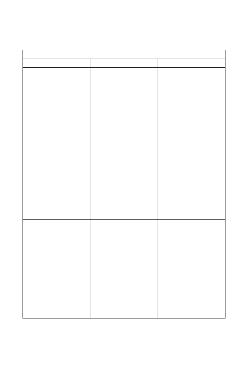
TABLE 8.2 TROUBLESHOOTING GUIDE (BATTERY BACKUP WITH EXTERNAL BATTERY)
Symptom Possible Cause Remedy
ON / OFF Switch is ON
• Switch is NOT lighted
• Load is ON and is operating
normally
• Output voltage at the Battery
Terminals is < 13.5 ± 0.2V and
is dropping
• Output voltage at the Load Terminals is up to 0.4 VDC lower
than the Battery Terminals and
is dropping
ON / OFF Switch is ON
• Switch is lighted
• Load is ON and is operating
normally
• Output voltage at the
Battery terminals is
<13.5V ± 0.2V and is dropping
• Output voltage at the Load Terminals is up to 0.4 VDC lower
than the Battery Terminals and
is dropping
ON / OFF Switch is ON
• Switch is lighted
• Load is ON
• Output voltage at the Load
Terminals loses regulation and
drops below 13.8 ± 0.2V
• Output voltage at the Load Terminals is up to 0.4 VDC lower
than the Battery Terminals and
is dropping
No AC power from the
AC outlet
Internal AC side fuse of the Power
Supply Section is blown
Power Supply Section of the Unit
has shut down due to over temperature – Temperature of output
transformer windings is
≥ 105°C ± 5°C / 221°F ± 9°F.
Power Supply Section is overloaded and is in current limit
condition. The load is trying to
draw excessive current ≥ the
current limit value of 25A. The
Time Current Characteristic of
the 25A fuse (F2, Fig 2.1) in the
Load circuit will determine the
allowable value of overload current > 25A and the time it can be
sustained before the fuse blows.
The allowable value will be higher
for shorter duration of overload.
Power Supply Section provides 25A
and the balance of current is fed
from the battery and the battery
starts discharging at current =
(Overload current - 25A)
Check AC power is available at
the AC outlet. Breaker feeding
the AC outlet may have tripped.
Open the top cover and check
the internal 6.3A AC side fuse.
Replace if blown.
If the fuse blows again, the input
section is damaged. Please call
Tech Support.
Check that the fan is running. if
not, the fan / fan control circuit
may have been damaged. Call
Tech Support.
Check that the fan suction vents
on the sides of the unit and the
discharge vents on the bottom of
the unit are not blocked.
The Power Supply Section will
reset automatically when the
transformer windings cool down
to ≤ 75°C ± 5°C / 167°F
± 9°F. During the time the Power
Supply Section is OFF, the battery
will supply the load and will
discharge during this period.
Remove the cause of overload
28 | SAMLEX AMERICA INC.
Page 29

SECTION 8 | Troubleshooting Guide
TABLE 8.2 TROUBLESHOOTING GUIDE (BATTERY BACKUP WITH EXTERNAL BATTERY)
Symptom Possible Cause Remedy
ON / OFF Switch is ON
• Switch is lighted
• There is no voltage at the at
the load end and the load is
shut down
• Voltage at the Load Terminals is
13.8 ± 0.2V
• Voltage at Battery Terminals is
lower than the voltage at the
Load terminals and is
≤ 13.5 ± 0.2V or lower
ON / OFF Switch is ON
• Switch is lighted
• Load is ON
• Voltage at the Load Terminals is
13.8 ± 0.2V
• Voltage at Battery Terminals is
the same as the Load Terminals
• Battery backup function does
not operate – Load shuts OFF
when AC power is interrupted
GFCI outlet / GFCI breaker
supplying AC power to the unit
trips when the unit is switched
ON
25A Fuse F2 (Fig 2.1) in the Load
circuit is blown due to:
- Excessive short time overload
current > 25A exceeding the
Time Current Characteristics of
the 25A fuse, or
- Short circuit in the load circuit
25A Fuse F1 (Fig 2.1) in the
battery circuit is blown due to:
- Reversal of battery input
connections
- Short circuit in the battery
wiring
Additional RF noise current from
the unit that is ltered to Earth
Ground increases the net Leakage
Current on the GFCI outlet / GFCI
breaker to > 4 to 6mA
Remove the cause of the overload
or short circuit
Check that the polarity of battery
connections is correct. Replace
the fuse.
Check for short circuit in the
battery wiring and correct.
Switch OFF other SMPS devices
operating from the same GFCI
outlet / GFCI breaker to reduce
the net leakage current to < 4mA.
Move the unit to another GFCI
outlet / GFCI breaker that has
lesser number of SMPS load(s) or
no SMPS load.
Power the unit from normal, non
GFCI outlet or from an outlet not
protected by GFCI breaker.
Page 30
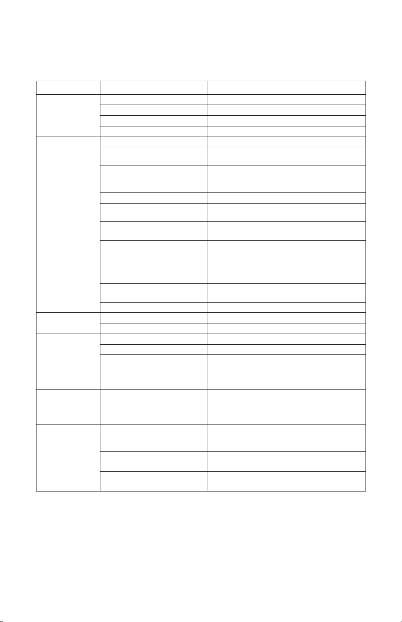
SECTION 9 | Specications
CATEGORY PARAMETER SPECIFICATION
Input Voltage 230 VAC (200-260 VAC), 50/60 Hz
AC INPUT
DC OUTPUT
EXTERNAL
BACKUP BATTERY
PROTECTIONS
COOLING Forced Air Temperature controlled fan. ON when Power
Input Current 2.75A @ 230 VAC
Input Current at No Load 105mA ± 10%
Inrush current at Startup 32A ±5% for 2.4 ms
Output Voltage at Load Terminals 13.8 VDC ± 0.2V
Output Voltage at Battery
Terminals (Without battery)
Output Voltage at Battery
Terminals (With battery)
Output Voltage Noise and Ripple < 150 mV Peak to Peak
Continuous Output Current at
Load Terminals
Continuous Output Current at
Battery Terminals (Battery Backup)
Output Current Limit at Load
Terminals
Output Current Limit at Battery
Terminals (Battery Backup)
Peak Efciency 85% ± 5%
Type & Voltage Lead Acid, 12V
Capacity 40Ah to 100 Ah
Short Circuit, Overload External 25A Fuse will blow
Over Voltage Regulated by PWM Controller
Over Temperature
(Power Supply Section)
Internal AC Side Fuse - 5 mm x 20 mm Glass Fuse
External Battery Side Fuse (By
FUSES
User)
External Load Side Fuse (By User) - 32V, 25 A, Fast Acting
13.8 VDC ± 0.2V
(i) Less than 13.5V ± 0.2V when not fully charged
(ii) 13.5V ± 0.2V when battery is fully charged and
oating
19A (With battery backup);
23A (Without battery backup)
Up to 4A (When battery is completely discharged to
Standing Voltage of 11.1V)
- 25A for 100 sec (External 25A fuse will blow)
- Surge > 25A as permitted by Time Current
Characteristics of 25A load side fuse (In Battery
backup Mode)
4A (When battery is completely discharged to
Standing Voltage of 11.1V)
Output of Power Supply Section shuts down when
Power Transformer winding temperature ≥ 105°C ±
5°C / 221°F ± 9°F); Auto reset on cooling down to
≤ 75°C ± 5°C / 167°F ± 9°F
Transformer winding temperature is ≥ 60°C ± 5°C
/ 140°F ± 9°F; OFF when cools down to ≤ 40°C ±
5°C / 104°F ± 9°F
- 250V, 4A, Time Delay Type
- Bussmann: “GDC-4” ; Littelfuse : 218004
- 32V, 25 A, Fast Acting
- Within 7” of the Battery Positive Post
- Within 7” from Load Terminal of the unit
30 | SAMLEX AMERICA INC.
Page 31
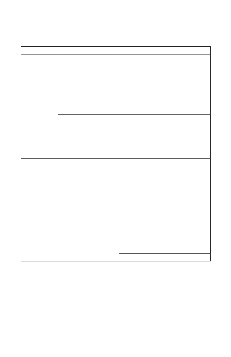
SECTION 9 | Specications
CATEGORY PARAMETER SPECIFICATION
Safety Low Voltage Directive (LVD) 2006/95/EC and
Electro-Magnetic Interference
(EMI)
COMPLIANCE
Electro-Magnetic Susceptibility European Council Directive 2004/108/EC
AC Input Connection - “IEC 320-C14” Inlet Connector on the unit
INPUT / OUTPUT
CONNECTIONS
ENVIRONMEN-
DIMENSIONS
& WEIGHT
NOTE: 1. All Specications given above are at ambient temperature of 25C / 77F unless
specied otherwise.
2. Above specications are subject to change without notice
DC Output Connectors for Load
and Battery Connections
Battery wires Minimum AWG #10 as per NEC Table 310.15(B)(17):
Operating Temperature Range 0°C / 32°F to 30°C / 86°F
TAL
Dimensions (W x D x H)
Weight
2014/35/E
IEC 60950-1:2005 (2nd) + A1:2009
EN 60950-1:2006 + A11:2009 + A1:2010 +
A12:2011
AS/NZS 60950-1:2011 + A1:2012; ANNEX ZZ
Variations
European Council Directive 2004/108/EC
EN 55022:2010; Class-B
EN 61000-3-2:2006+A1:2009+A2:2009
EN 61000-3-3:2013
AS/NZS CISPR 22 (2009+A1:2010), Class B; (C-TICK)
EN55024:2010 ; Class-B
EN61000-4-2:2009
EN61000-4-3:2006+A2:2010
EN61000-4-4:2012
EN61000-4-5:2006
EN61000-4-6:2009
EN61000-4-8:2010
EN61000-4-11:2004
- Detachable Power Cord with: “IEC 320-C13”
Connector on one end and CEE-7/7 “Schuko”
Plug on the other end
Terminal with Tubular Hole - Diameter 5mm / 0.2”
and set screw (5/64” Hex Socket Head, #10,
24 TPI, 5/16” long)
- Ampacity 40A (1.25 times Maximum current
of 25A)
- Conductor temperature rating of 90°C / 194°F
185 x 240.5 x 61 mm
7.28 x 9.47 x 2.40 in
1.6 kg
3.4 lb
Page 32

SECTION 10 | Warranty
3 YEAR LIMITED WARRANTY
SEC-1223BBM-CE manufactured by Samlex America Inc. (the “Warrantor“) is warranted
to be free from defects in workmanship and materials under normal use and service.
The warranty period is 3 years for the United States and Canada, and is in effect from
the date of purchase by the user (the “Purchaser“).
Warranty outside of the United States and Canada is limited to 6 months. For a warranty
claim, the Purchaser should contact the place of purchase to obtain a Return Authorization Number.
The defective part or unit should be returned at the Purchaser’s expense to the authorized location. A written statement describing the nature of the defect, the date of purchase, the place of purchase, and the Purchaser’s name, address and telephone number
should also be included.
If upon the Warrantor’s examination, the defect proves to be the result of defective
material or workmanship, the equipment will be repaired or replaced at the Warrantor’s option without charge, and returned to the Purchaser at the Warrantor’s expense.
(Contiguous US and Canada only)
No refund of the purchase price will be granted to the Purchaser, unless the Warrantor
is unable to remedy the defect after having a reasonable number of opportunities to do
so. Warranty service shall be performed only by the Warrantor. Any attempt to remedy
the defect by anyone other than the Warrantor shall render this warranty void. There
shall be no warranty for defects or damages caused by faulty installation or hook-up,
abuse or misuse of the equipment including exposure to excessive heat, salt or fresh
water spray, or water immersion.
No other express warranty is hereby given and there are no warranties which extend
beyond those described herein. This warranty is expressly in lieu of any other expressed
or implied warranties, including any implied warranty of merchantability, tness for the
ordinary purposes for which such goods are used, or tness for a particular purpose, or
any other obligations on the part of the Warrantor or its employees and representatives.
There shall be no responsibility or liability whatsoever on the part of the Warrantor or
its employees and representatives for injury to any persons, or damage to person or
persons, or damage to property, or loss of income or prot, or any other consequential
or resulting damage which may be claimed to have been incurred through the use or
sale of the equipment, including any possible failure of malfunction of the equipment,
or part thereof. The Warrantor assumes no liability for incidental or consequential damages of any kind.
Samlex America Inc. (the “Warrantor”)
www.samlexamerica.com
32 | SAMLEX AMERICA INC.
Page 33

Notes
Page 34

Contact
Information
Toll Free Numbers
Ph: 1 800 561 5885
Fax: 1 888 814 5210
Local Numbers
Ph: 604 525 3836
Fax: 604 525 5221
Website
www.samlexamerica.com
USA Shipping Warehouses
Kent, WA
Plymouth, MI
Canadian Shipping Warehouse
Delta, BC
11001-SEC-1223BBM-CE-1218
Email purchase orders to
 Loading...