

Samho SH-1053, SH-1054, SH-1055, SH-1056 Service Manual
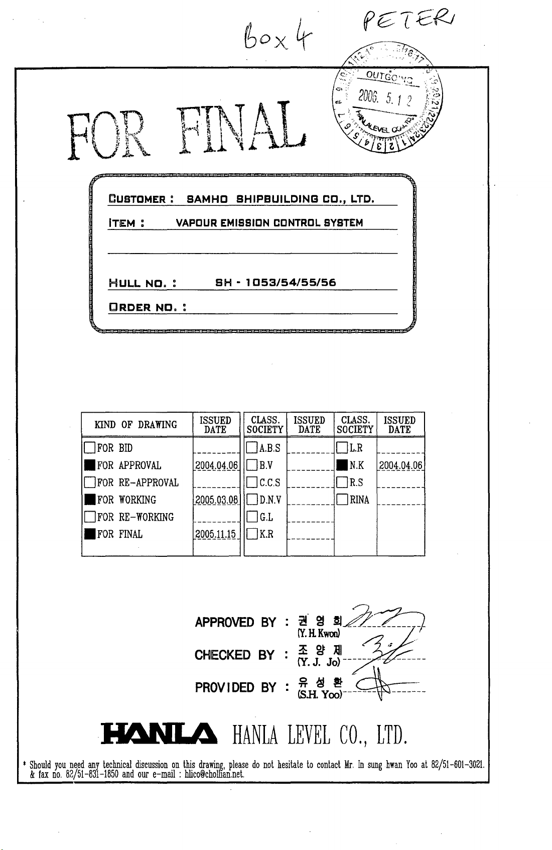
CUSTOMER:
SAMHO
SHIPBUILDING
CO.,
LTD.
KIND
DFOR
•
FOR
DFOR
•
FOR
D
FOR
.FOR
ITEM
HULL
CRDER
: VAPOUR EMISSION CONTROL SYSTEM
NO.
NO.
OF
DRAWING
BID
APPROVAL
RE-APPROVAL
WORKING
RE-
WORKING
FINAL
:
:
SH -1053/54/55/56
ISSUED
DATE
--------
~QJL1,QLO~
--------
~QO_5~Q~JlJl
--------
~QQ5_,lLl~
CLASS.
SOCIETY
DA.B.S
DB.V
Dc.c.s
DD.N.V
DG.L
DK.R
ISSUED
DATE
--------
--------
--------
--------
--------
--------
CLASS.
SOCIETY
DL.R
.N.K
DR.S
DRINA
ISSUED
DATE
--------
~QQ1,QtP~
--------
--------
*
Should
&
fax
you
need
no.
any
82/51-831-1850
technical
and
APPROVED
CHECKED
PROV
discussion
our
on
this
e-mail : hlico@chollian.net.
drawing,
BY
BY
IDEO
please
BY
HAN
LA
do
not
:
~.
gJ
(Y.RKwoo)
.
~~~I
. (Y. J.
:.H.
LEVEL
hesitate
§JA~~-_~
Jo)
~yJ---4m---
CO.,
to
contact
------
Mr.
In
,;
------
LTD.
sung
ban
Yoo
at
82/51-601-3021.
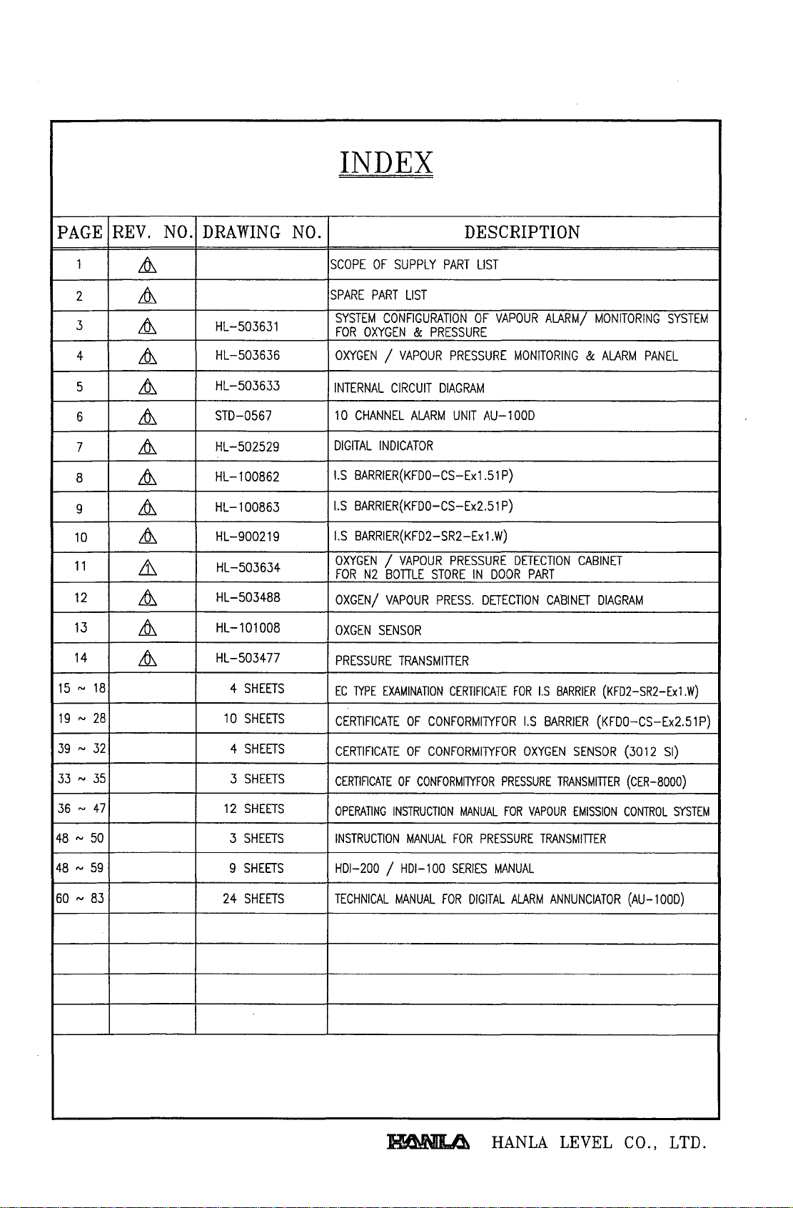
INDEX
PAGE
1
2
3
4
5
6
7
8
9
10
11
12
13
REV.
&
&
&
&
&
&
&
&
&
&
&
&
&
NO.
DRAWING
HL-503631
HL-503636
HL-503633
STD-0567
HL-502529
HL-100862
HL-100863
HL-900219
HL-503634
HL-503488
HL-101008
NO.
SCOPE
SPARE
SYSTEM
FOR
OXYGEN / VAPOUR
INTERNAL
10
CHANNEL
DIGITAL
I.S
BARRIER(KFDO-CS-Ex1.51
I.S
BARRIER(KFDO-CS-Ex2.51
I.S
BARRIER(KFD2-SR2-Ex1.W}
OXYGEN / VAPOUR
FOR
OXGEN/
OXGEN
DESCRIPTION
OF
SUPPLY
PART
CONFIGURATION
OXYGEN & PRESSURE
CIRCUIT
INDICATOR
N2
BOTTLE STORE
VAPOUR
SENSOR
LIST
ALARM
PART
LIST
OF
PRESSURE
DIAGRAM
UNIT
PRESSURE
IN
PRESS.
DETECTION
AU-100D
VAPOUR
P}
P}
DOOR
ALARM/
MONITORING & ALARM
DETECTION
PART
CABINET
CABINET
MONITORING
PANEL
DIAGRAM
SYSTEM
14
15 N 18
19 N 28
39 N 32
33 N 35
36 N 47
48 N 50
48 N 59
60 N 83
&
HL-503477
4
SHEETS
10
SHEETS
4
SHEETS
3
SHEETS
12
SHEETS
3
SHEETS
9
SHEETS
24
SHEETS
PRESSURE
EC
TYPE
CERTIFICATE
CERTIFICATE
CERTIFICATE
OPERATING
INSTRUCTION
HDI-200
TECHNICAL
TRANSMITTER
EXAMINATION
OF
OF
OF
INSTRUCTION
MANUAL
/ HDI-l00
MANUAL
CERTIFICATE
CONFORMITYFOR
CONFORMITYFOR
CONFORMIlYFOR
FOR
SERIES
FOR
PRESSURE
MANUAL
PRESSURE
MANUAL
DIGITAL
FOR
ALARM
FOR
I.S
BARRIER
I.S
BARRIER
OXYGEN
TRANSMITTER
VAPOUR
TRANSMITTER
ANNUNCIATOR
(KFD2-SR2-Exl.W)
(KFDO-CS-Ex2.51
SENSOR
EMISSION
(3012
(CER-8000)
CONTROL
(AU-lOOD)
p)
SI)
SYSTEM
IIC!\lIL4
HANLA
LEVEL
CO.,
LTD.
WORK
NO
; SH-1053/54/55/56
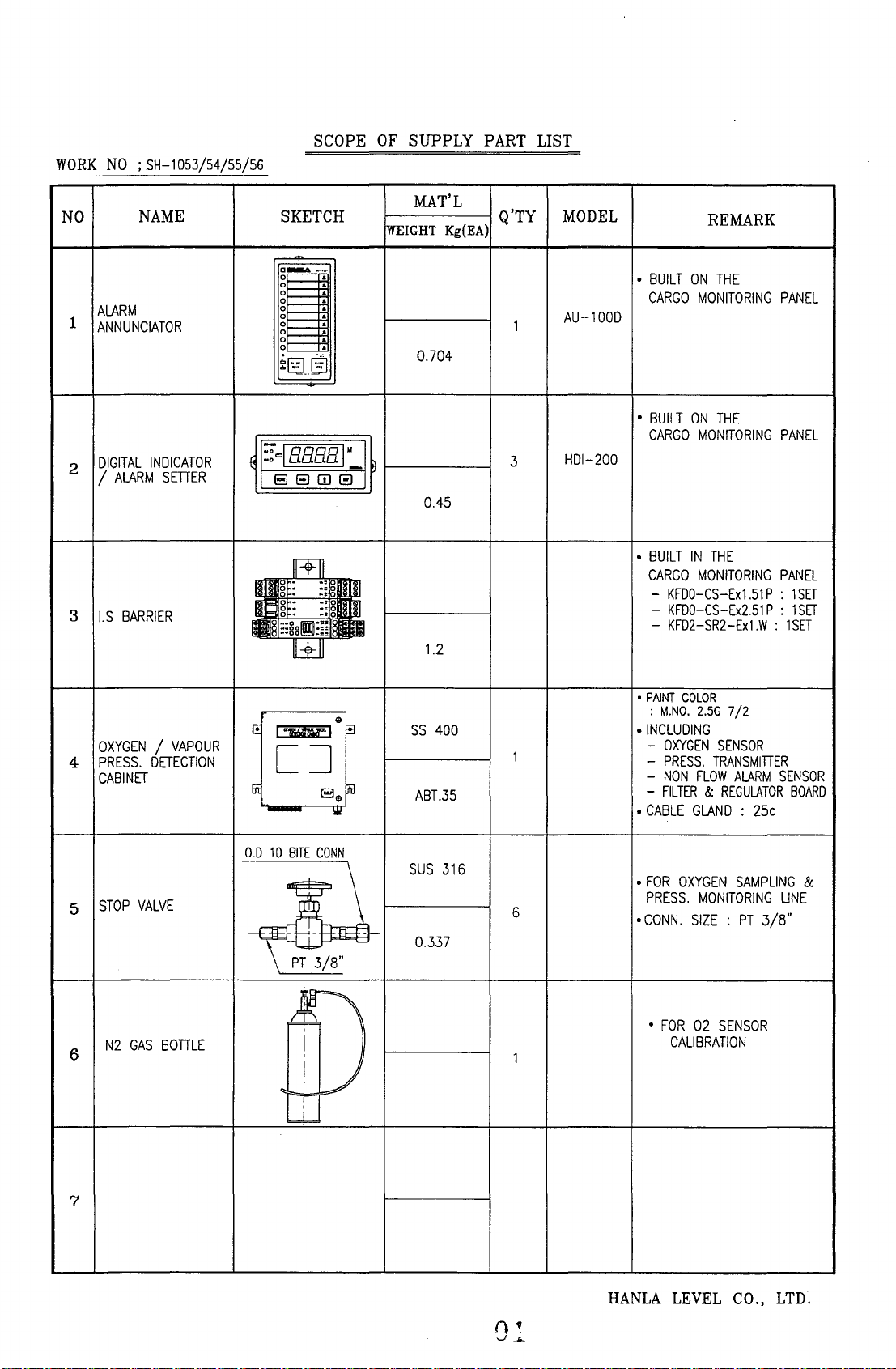
SCOPE
OF
SUPPLY
PART
LIST
NO
ALARM
1
ANNUNCIATOR
DIGITAL
2
/
ALARM
3
I.S
NAME
INDICATOR
SETTER
BARRIER
MAT'L
SKETCH
a~_._
gl
01---
gr--
gl
gl
~L-_~
,,!§§
Co·"
....
t
:"'laaaaI
88IT1B
[wEIGHT
:
•
:
Kg(EA)
:
:
0.704
M
~
0.45
Q'TY
1
3
m
l~iI
W
1.2
MODEL
AU-lOOD
HDI-200
REMARK
•
BUILT
ON
THE
CARGO
•
BUILT
CARGO
•
BUILT
CARGO
MONITORING
ON
THE
MONITORING
IN
THE
MONITORING
-
KFDO-CS-Ex1.S1P : 1SET
-
KFDO-CS-Ex2.S1
-
KFD2-SR2-Ex1.W : 1SET
PANEL
PANEL
PANEL
P : 1
SET
OXYGEN / VAPOUR
4
5
6
PRESS.
CABINET
STOP
N2
GAS
DETECTION
VALVE
BODLE
•
PAINT
COLOR
;
M.NO.
•
INCLUDING
-
OXYGEN
-
PRESS.
-
NON
-
FILTER & REGULATOR
•
CABLE
GLAND : 25c
•
FOR
OXYGEN
PRESS.
•
CONN.
SIZE : PT
•
FOR
02
CALIBRATION
BITE
,
I
,
e
II
iiil
8
e
III
CONN.
SS
400
1
ABT.35
SUS
316
6
0.337
11
1
E!
I~I
[J
Iili
-
0.0
10
~8.\
I
:
1
w...
2.5G
7/2
SENSOR
TRANSMIDER
FLOW
ALARM
SAMPLING
MONITORING
3/8"
SENSOR
SENSOR
BOARD
&
LINE
7
HANLA
LEVEL
CO.,
LTD.

WORK
NO
; SH-l053/54/55/56
SPARE PART LIST
NO
1
2
3
NAME SKETCH MAT'L
SPARE
PART
BOX
c:r
FUSE
r--50-~~
MONKEY
WRENCH
~
SS41
STEEL
Q'TY
lSHIP
1
5
1
MODEL
SB-Cl
REMARK
*
PAINT
COLOR
:
M.NO.
7.5
* SIZE:
200 x 200 x 100
*
SS41.
1.2t
•
CAPACITY
:
AC
500V.
DC
3A
• 6"
8G
250V.
7/2
4
5
6
7
SCREW
(CROSS
FILTER
DRIVER
HEAD
TYPE)
~
--~---
-------
~~
I 0 5 I
SUS
SUS316
STEEL
304/
1
5
HANLA LEVEL CO., LTD.
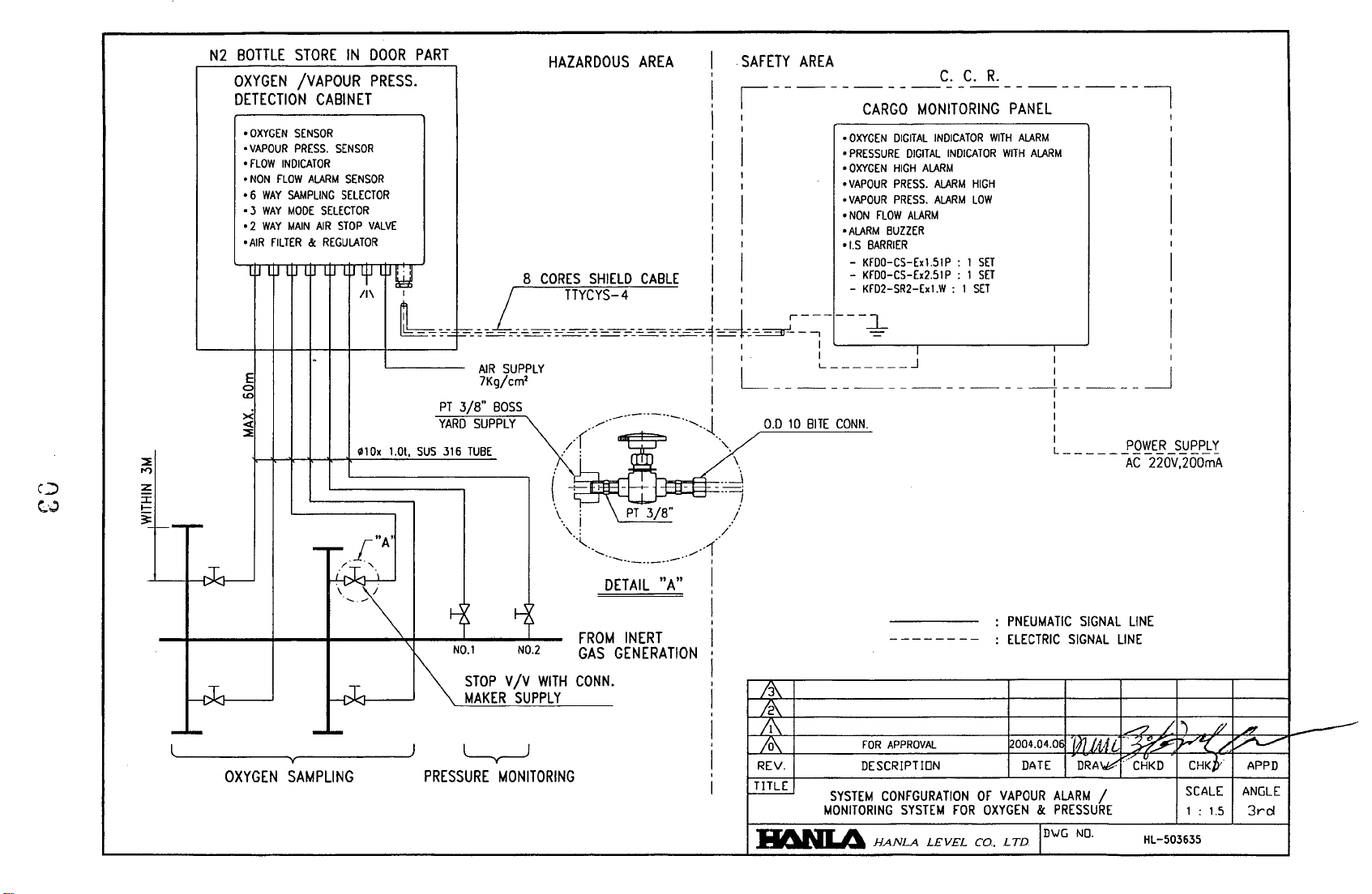
N2
BOTTLE
OXYGEN
DETECTION CABINET
o
oVAPOUR
o
o
06
03
02
o
STORE
/VAPOUR
OXYGEN
SENSOR
PRESS.
FLOW
INDICATOR
NON
FLOW
ALARM
WAY
SAMPLING
WAY
MODE
WAY
MAIN
AIR
FILTER & REGULATOR
11.1
I~ l~ l~ l~
IN
SENSOR
SENSOR
SELECTOR
SELECTOR
AIR
STOP
l~
4.J
,:,
DOOR
PRESS.
VALVE
l~
~:
:-
L
PART
II
-=-=-
f:==:
8
L
~
=-=
=-':
~
HAZARDOUS AREA
o
OXYGEN
DIGITAL
o
PRESSURE
o
OXYGEN
o
VAPOUR
o
VAPOUR
o
NON
FLOW
o
ALARM
ol.S
BARRIER
-
CORES
SHIELD
TTYCYS-4
=-'"-=::=::~
CABLE
===-=-:~
-=-:.=::==::.1
I
,:
"'-:=J.:
~
,I
r
____
-,
KFDO-CS-Ex1.51P
-
KFDO-CS-Ex2.51P.:
~::-SR2-[.'.W
I
-=-
'------'1--------,,-----'
DIGITAL
HIGH
AlARM
PRESS.
PRESS.
ALARM
BUZZER
INDICATOR
AlARM
ALARM
WITH
INDICATOR
. ,
HIGH
LOW
: 1
SET
1
SET
SO
WITH
ALARM
ALARM
I
L----~-E-I---HI--I-.
-
---
L~-----~yr------~)
OXYGEN SAMPLING
-t--t---t------'
010x
-r-
I
~.~.
'-\
t-t.-.rI;>'<
.....
~_~1
~
~
--
1.01.
"A'
PT
3/8"
YARD
sus
316
NO.1
~
'\
STOP
MAKER
~
PRESSURE
~:,J~!fLY
BOSS
SUPPLY
TUBE
MONITORING
NO.2
V
Iv
SUPPLY
(~
\
WITH
-.----.-----
/.(/
~
..
, : /
..
,......
GAS
CONN.
\
I
----
DETAIL
FROM
GENERATION
in
PT
3/8"
_______
INERT
"A"
: L
,
........
1 0.0
'
...
\
-
-::~
- /
.-
/'1'
" t
!
I
,
I
,
I
,
I
,
I
,
I
REV.
TITLE
-
-.:.-A.
~
__
~
=
10
BITE
SYSTEM
MONITORING
.....
........
CONN.
=::.::::
= = J
FOR
APPROVAL
DESCRIPTION
CONFGURATION
SYSTEM
A.
HANLA
__
LEVEL
- - - - -
OF
FOR
Co..
-i
:
PNEUMATIC
:
ELECTRIC
~004.04.0f
DATE
VAPOUR
OXYGEN & PRESSURE
lD\JG
LTD
______
:
~
-----
SIGNAL
SIGNAL
ldlJA1L
DRA""""
ALARM
NO.
j
{g~i~of~~~\
LINE
LINE
~jr'
:::/CHKD
/
HL-503635
'<:
CHKJy
SCALE
1 :
1.5
/.~
APPD
ANGLE
3rd
+I.S
BARRIER
NON
FOR
I.S
CABLE!
V,AJlOUR
I
I.S
CABLE
i
EMISSION
CONffiOL
SYSTEM
+
II
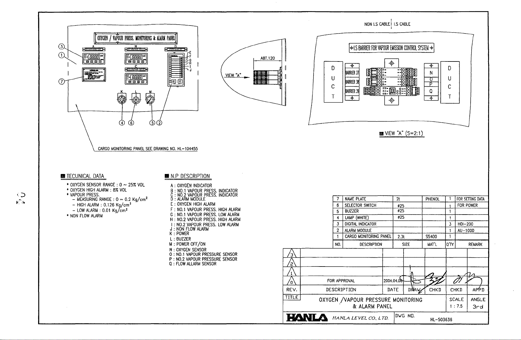
TECUNICAL
*
OXYGEN
•
OXYGEN
•
VAPOUR
-
MEASURING
-
HIGH
-
LOW
*
NON
FLOW
CARGO
DATA
SENSOR
HIGH
ALARM:
PRESS.
RANGE:
ALARM:
ALARM:
ALARM
MONITORING
RANGE
: 0 N
8%
0 NO.2 Kg/cm
0.126
Kg/cm
0.01
Kg/cm
VOL
25%
2
PANEL
2
VOL
SEE
DRAWING
2
NO.
HL
•
N.P
DESCRIPTION
A :
OXYGEN
B :
NO.1
C :
NO.2
D :
ALARM
E :
OXYGEN
F :
NO.1
G :
NO.1
H :
NO.2
I :
NO.2
J :
NON
K:
POWER
L:
BUZZER
M :
POWER
N
OXYGEN
o
NO.1
P
NO.2
Q
FLOW
-104455
INDICATOR
VAPOUR
VAPOUR
MODULE
HIGH
VAPOUR
VAPOUR
VAPOUR
VAPOUR
FLOW
OFF
SENSOR
VAPOUR
VAPOUR
ALLARM
PRESS.
PRESS.
ALARM
PRESS.
PRESS.
PRESS.
PRESS.
ALARM
ION
PRESSURE
PRESSURE
SENSOR
INDICATOR
INDICATOR
HIGH
ALARM
LOW
ALARM
HIGH
ALARM
LOW
ALARM
SENSOR
SENSOR
0
U
C
T
7
6
5
4
3
2
1
NO.
IER
I]
IER
3
NAME
PLATE
SELECTOR
BUZZER
LAMP
DIGITAL
ALARM
CARGO
SWITCH
(WHITE)
INDICATOR
MODULE
MONITORING
DESCRIPTION
III
VIEW
PANEL
"A" (S=2:1)
2t
¢25
¢25
¢25
2.3t
SIZE
0
U
C
~
PHENOL
SS40D
MAT'L
T
1
1
3
1
1
Q'TY
FOR
SETTING
FOR
POWER
HDI-200
AU-lOOD
REMARK
DATA
OXYGEN
II6NI.4
FOR
APPROVAL
DESCRIPTION
/VAPOUR
. &
HANLA
LEVEL
PRESSURE
ALARM
Co., L
PANEL
rD.
MONITORING
D\JG
NO.
HL-503636
SCALE
1 : 7.5
ANGLE
3rd
P40
------.
ON-OFF
S/W
~
0
\D-r-----
~--'-'-'----------___'_______'______r____r__-r______ol
P41
N40
~----~oo-
~4-------~~----------------------------------------~
N41
1107
r-----<
~
r
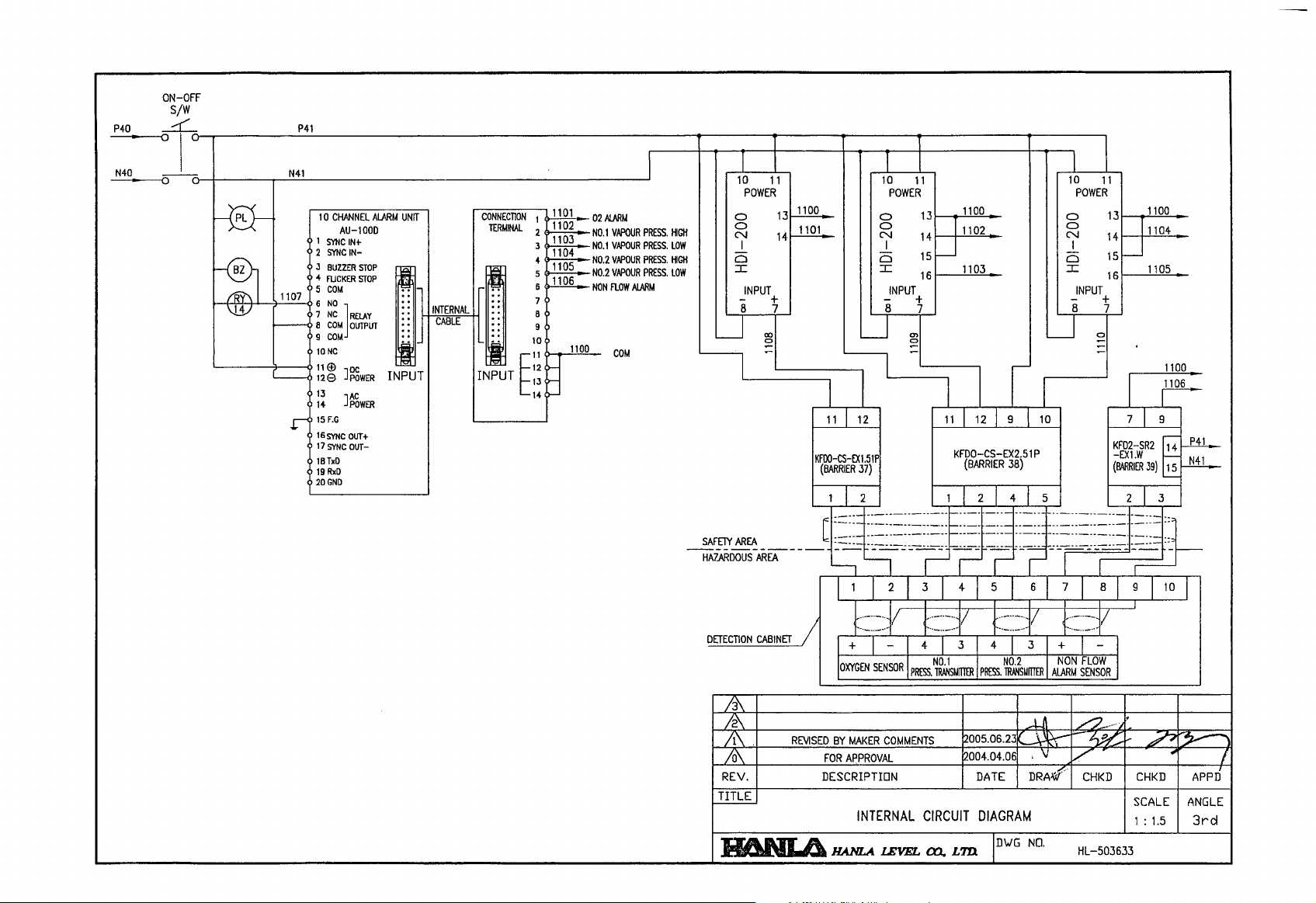
10
CHANNEL
AU-lOaD
1
SYNC
IN+
2
SYNC
IN-
J
BUZZER
STOP
4
FUCKER
STOP
5
COM
6
NO
7
NC
]RElAY
B
COM
OUTPUT
9
COM
10NC
lIE!)
]~WER
128
13
]~gWER
14
15
F.G
16
SYNC
OUT+
17
SYNC
OUT-
lBTxD
19RxD
20GND
AlJ.RM
INPUT
UNIT
I
..
..
..
..
..
..
..
..
I
INTERNAL
CABLE
CONNECTION
TERMINAL
5
7
..
..
..
i 10
8
11
INPUT
E:!
I I I
1
~02ALARt.I
1102
2
11
03
NO.1
VAPOUR
3
4
6
B
9
~
~
~
~
NO.1
NO.2
NO.2
NON
1100
PRESS.
VAPOUR
PRESS.
VAPOUR
PRESS.
VAPOUR
PRESS.
flOW
ALARM
COM
~
10
11
POWER POWER
o
HIGH
LOW
HIGH
LOW
~f!!Y
o
N
I
Cl
:c
INPUT
+
8 7
~:g
AR~
_____
HAZARDOUS
AREA
~~
11
12
FllO
CS
EX
K
(BARRIER
ji)l r
12
C
~~~~~
'---l
"---J
I 1 2 I 3 I 4 I 5 6 7 I 8 I 9 I
:=::=::~I
DETECTION
CABINET
/ 1 + - 1 4 1 3 1 4 3
10XYGEN
10
10
o
o
N
I
Cl
:c
INPUT
- +
8 7
11
13
1100
14
11102
15~
161-----'.1
""I
0",3_
POWER
o
o
N
I
Cl
:c
INPUT
- +
8 7
11
13
1100
14
11104
15~
161----'-11""'0""5_
~~
-
-
1100
~
11
12
"
5
~~~~~~L~~~§~~E~~~
KFDO-CS-EX2.51
(BARRIER
12145
~~~~~~~~~~~~~-~~:~r-
I I I I
t::=::=::f
SENSOR I PRESS.
~S~ITIER
t::=::=::f
I
PRESS.
10
1 9
P -£Xl W
38)
7 I 9
KFD2-SR2
(BARRIER
2J3
1,--
-
..
---
..
~J
··_-·_··
..
r
+ 1 - 1
NON
FLOW
~SUITIER
ALARM
J
SENSOR
~4
39)
15
10
rill-
rJ!1.l---
I
/3\
REVISED
/0\
REV.
II6NLI.).
BY
MAKER
COMMENTS
FOR
APPROVAL
DESCRIPTION
INTERNAL
IlANLA
lEVEL
12005.06.23
12004.04.06
CIRCUIT
co.
LID
DA
TE
DIAGRAM
ID'WG
~-~
,\I
DRAW
NO.
V
CHKD
HL-503633
CHKD
SCALE
1 :
1.5
~
I
APPD
ANGLE
3rd
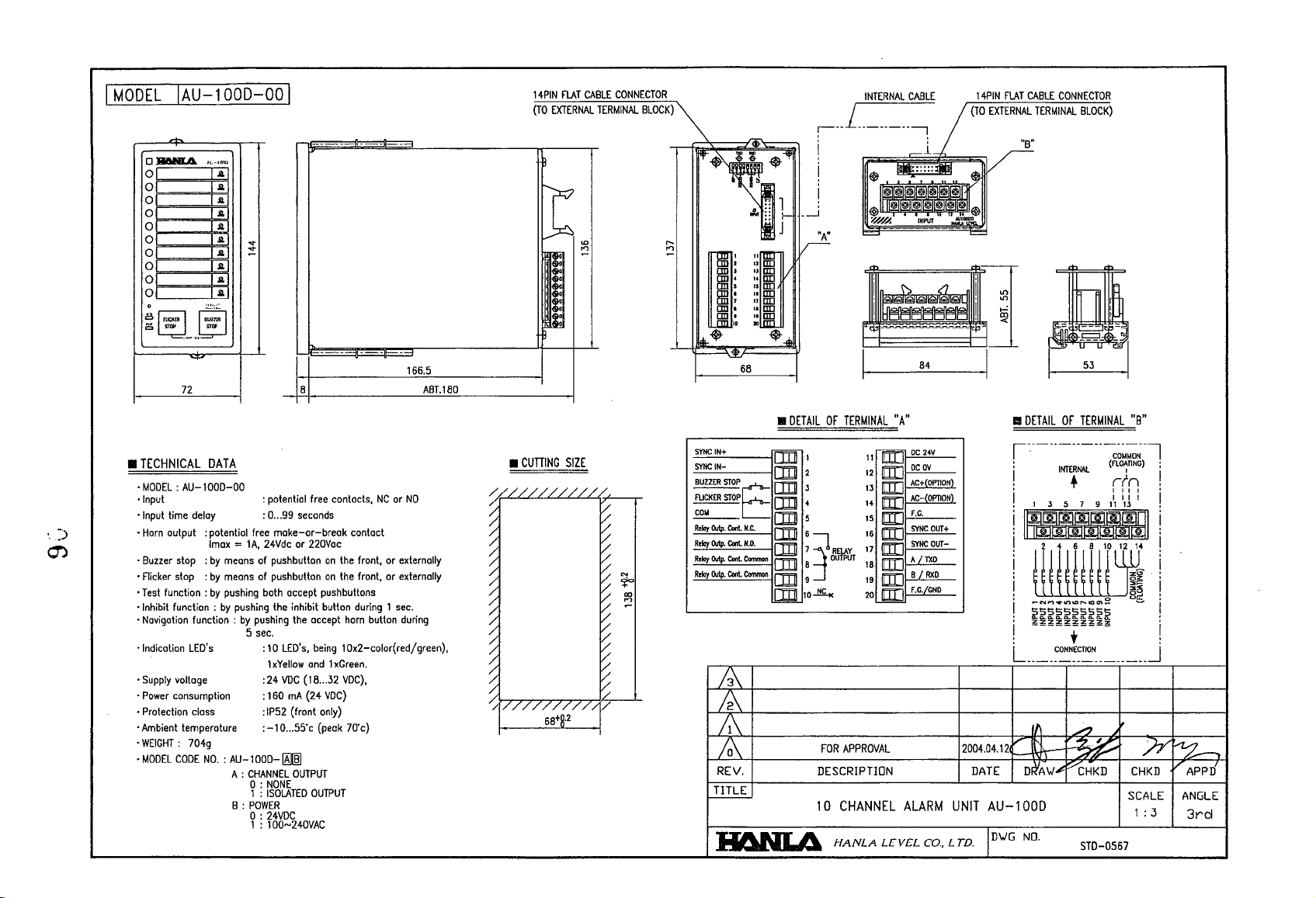
IMODEL
•
IAU-100D-Ool
OJl6N1A,
01
gl
o £
o~
o £
o £
01
01
01
o
~lru:1
TECHNICAL
•
MODEL:
•
Input
•
Input
•
Horn
•
Buzzer
•
Flicker
•
Test
•
Inhibit
•
Navigotion
.
Indication
•
Supply
•
Power
•
Protection
•
Ambient
WEIGHT:
•
•
MODEL
;,.~1I'11'll
1£1
1:1
....
....
-
1£1
1£1
1£1
STOP
SJIII
I-=~
I
"l'"
72
DATA
AU-1
000-00
time
delay
output : potential
Imax = 1A,
stop : by
stop : by
function:
function:
voltage
consumption
CODE
means
means
by
pushing
by
function:
LED's
closs
temperature
704g
NO.
: AU-100D-1AIffiI
pushing
by
5
A :
CHANNEL
B:
8
: potential
: 0
free
of
of
both
pushing
sec
:
:24
:
:IP52 (frant
:-10
o :
1 :
POWER
0:
1 :
free
...
99
seconds
make-or-breok contact
24Vdc
or
220Vac
pushbutton
pushbutton
the
.
10
1
xYeliow
160
NONE
ISOLATED
24VDC
100N240VAC
accept
pushbuttons
inhibit button
the
accept
LED·s.
being
and 1 xGreen.
VDC
(18
...
mA
(24
only)
...
5S·c
(peak
OUTPUT
OUTPUT
on
on
VDC)
- -
-
166.5
contacts,
NC
or
NO
the
front. or
externally
the
front. or
externally
during 1 sec.
horn
button
during
10x2-color(red/green),
32
VDC).
70'c)
ABT.180
14PIN
FlAT
(TO
EXTERNAL
~
IT:.
~
~
t
•
CUTTING
SIZE
CABLE
TERMINAL
I")
-
CONNECTOR
BLOCK)
_---1
68
•
DETAIL
SYNCIN+
SYNC
IN-
~Ec:m
FlICKER
STOP
~
Relay
CMp.
Relay
CMp.
Relay
CMp.
Re~y
CMp.
Coot
Coot
Coot
Coot
m
H.C.
H.D.
Common
Common
IJD
~
em
IJDS
em
6
IJD
7:=1
IJD
B
DIll
9 J
!DIlIIO~
IIIlNI.4
INTERNAL
CABLE
uL-_u_u
r-
-,
i :
i
I
OF
TERMINAL
~
CJpP-&
FOR
APPROVAL
DESCRIPTION
10
CHANNEL
HANLA
1'1iIJ
12
m:J
13
rn:J
[]JJ
IS
IIID
16
m:J
17
m:J
I B
m:J
19
IDII
20
JID
LEVEL
"A"
DC
DC
AC+(OPTION)
AC-(OPTION)
F.C.
SYNC
SYNC
A /lXD
B /
F.G.lGND
ALARM
(TO
24V
OV
OUT+
DUT-
RXD
2004.04.12~{
DATE
UNIT
Co.,
LTD.
EXTERNAL
TERMINAL
BLOCK)
"B"
..
DETAIL
OF
TERMINAL
J\..l)""--;-~~"'"
AU-100D
D\JG
NO.
STD-0567
"8"
SCALE
1 : 3
ANGLE
3rd
I
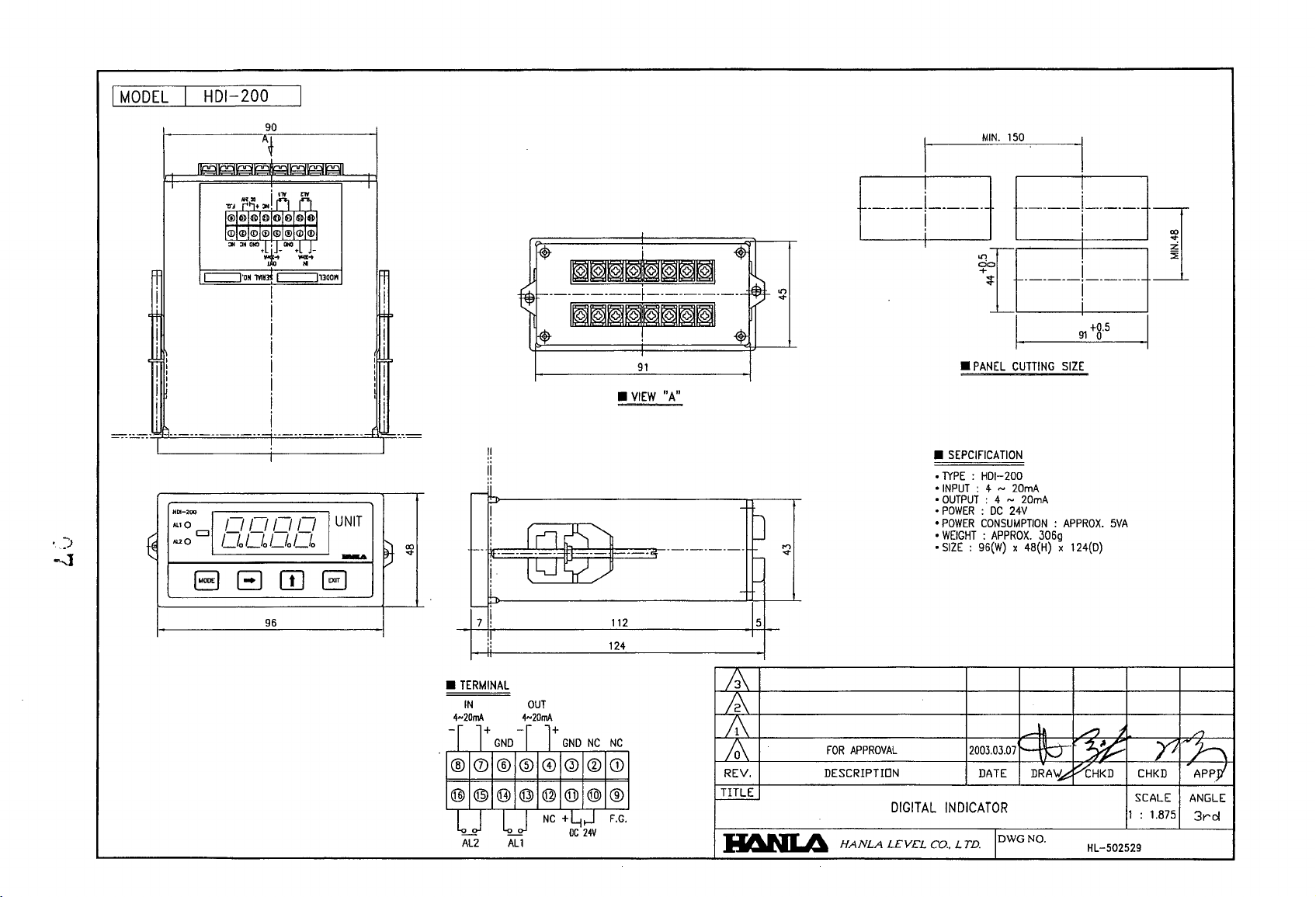
MODEL
I HDI-200 I
90
T
I~I
I
I
MIN_
150
I
~
!
i
Ii
, I
I I
i
==--
=
__
~~-::..:-
=-::..:-=-::..:-=-::..:-=-::..:-
c==J'OH
1V1!~
c==J1JOO"
I
i
i
i
i
i
i
i
=1'-=-
=-=-=-=-
!
I
96
=-=-=-=-
~
I
p
!
I
: I
I,
I I
i
-1=;=--,=
91
•
VIEW
"A"
•
.lYPE : HOI-200
•
DIGITAL
Co.,
•
•
•
•
•
--~-----------------------,,---,
! h
!
f----*=~~*:$=t=::::::::::~---------
Il[\']
i
l,Jy~
112
Ii
•
TERMINAL
IN
4~20mA 4~20mA
-r
l+
GNO
OUT
-I
l+
®0®®CDQ)®CD
@@(1)@@@@®
l
~
AL2
I l I
~
All
NC
+
GNO
NC
~~.
DC
24V
124
Ne
F.G.
W
l-
I-
-
5
7i,
REV,
TITLE
II6NL4
FOR
APPROVAL
DESCRIPTION
HANLA
LEVEL
•
PANEL
CUTTING
SEPCIFICATION
INPUT
: 4 ~ 20mA
OUTPUT
: 4 ~ 20mA
POWER : OC
POWER
WEIGHT : APPROX.
SIZE : 96(W) x 48(H)
INDICATOR
LTD.
24V
CONSUMPTION : APPROX_
2003.03.07
DATE
306g
--t'}v .
DRA~HKD
IDWG
NO.
91
+8.
SIZE
x 124(0)
~
HL-502529
5
5VA
CHKD
SCALE ANGLE
1 :
1.875
APr>i
3rcl
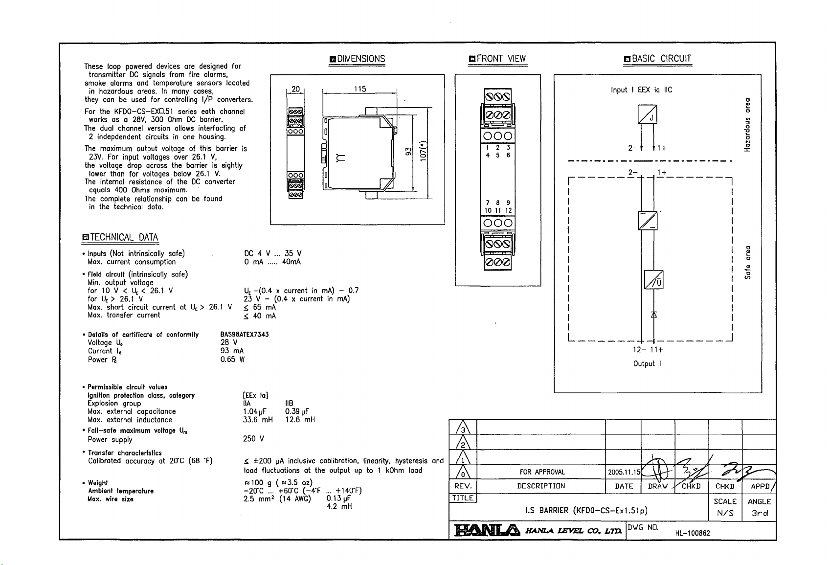
These
loop
tronsmitter
smoke
in
they
For
works
The
2 indepdendent circuits
The
23V.
the voltage drop across the barrier is sightly
lower than for voltages
The
equals
The
in
powered
alarms
hazardous areas.
can
be
the
KFDO-CS-EXD.51
as
a
dual channel
maximum output voltage of this barrier
For
input voltages over
internal resistance of the
400
complete relationship
the technical data.
mTECHNICAL
•
Inputs
(Not intrinsically safe)
Max.
current consumption
• field circuit (intrinsically safe)
Min.
output voltage
for
10
V < U
for U
>
26.1
E
Max.
short circuit current at U
Max.
transfer current
•
Details
of certificate
Voltage
U.
Current
I.
Power
Po
devices
In
many
Ohm
allows
in
below
can
ore
coses,
series
DC
one
26.1
26.1
DC
be
DC
signals from fire alarms,
and
temperature sensors located
used
for controlling
28V,
300
version
Ohms
maximum.
DATA
<
26.1
E
V
V
of
conformity
E
designed
I/P
converters.
eath
channel
barrier.
interfacting of
housing.
V,
V.
converter
found
>
26.1
V ~ 65
BAS98ATEX7343
28
93
0.65 W
for
is
DC
4 V
o
mA
.....
U
-(0.4
E
23
V - (0.4 x current
mA
~
40
mA
V
mA
...
35
V
40mA
x current
l'I
DIMENSIONS
115
0
0
:>-
)-
~
r~
in
mA)
- 0.7
in
mA)
I I
I I
L§
12
m
'"
~
r--
0
~
aFRONT
-
~~~
000
'"
000
1 2 3
456
769
10
11
000
'" '"
~OO
000
-
VIEW
'"
12
£!
BASIC
Input I
EEX
2-
r------
--------1
=-
[
,......=
I
I
I
L
______________
12-
11+
Output
CIRCUIT
ia
IIC
1+
I
o
.,
....
o
en
::J
o
1!
o
N
o
::r::
o
~
o
.,
'0
Vl
~
•
Permissible
Ignillon
Explosion
Max.
Max.
• Fall-safe
Power
•
Transfer
Calibrated accurocy at
•
Weight
Ambient
Max,
circuit
protecllon
external capacitance
external inductance
supply
characterisllcs
temperature
wire
values
class,
group
maximum
size
category
voltage
20'C
U
m
(68 'F)
[EEx
la]
IIA
1.04IJF
33.6
250 V
:!>:
±200
load
Rll00 g (Rl3.5 oz)
-20'C
2.5
liB
0.391JF
mH
12.6
(JA
inclusive cablibration, linearity, hysteresis
fluctuations at
...
+60'C
(14
(-4'F
AWG)
mm
2
mH
the
output
up
... + HO'F)
O.131JF
4.2
mH
to 1
kOhm
load
and
/0\
REV.
TITLE
~
FOR
APPROVAL
DESCRIPTION
I.S
BARRIER
HANLA.1EVEL
2005.11.15~l
DATE DRA\.I
(KFDO-CS-Exl.Sl
00
..
LTD.ID\.IG
p)
NO.
'-Y.£
.•
VCHKD
HL-l00B62
~l:?--
CHKD'
SCALE
N/S
APPD
ANGLE
3rd
/
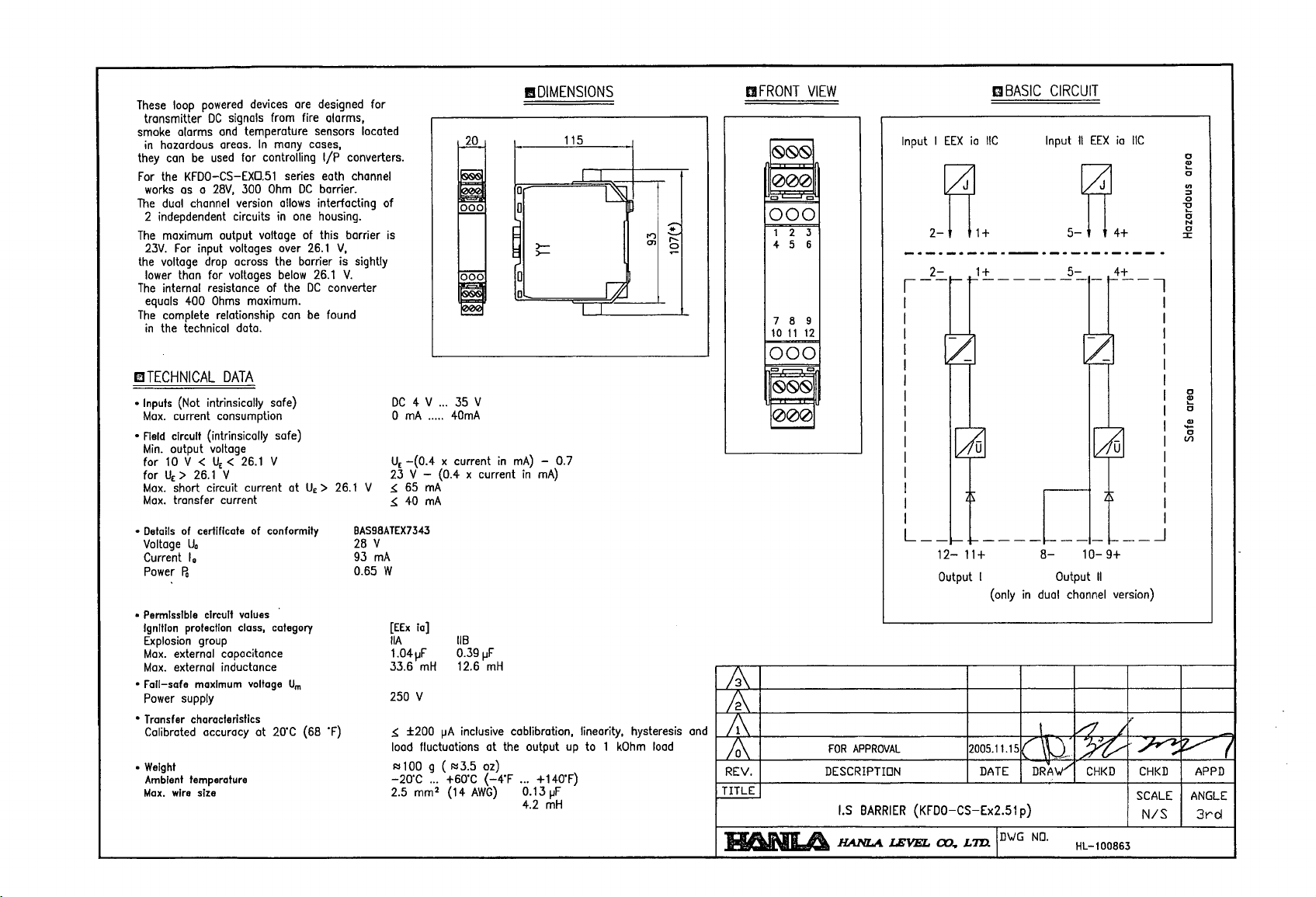
These
loop
transmitter
smoke
in
they
For
works
The
2 indepdendent circuits
The
23V.
the voltage
lower thon for voltages
The
equals
The
in
powered
alarms
hozardous areas.
can
be
the
KFDO-CS-EXD.51
as a 28V,
duol
channel version
maximum output voltage of this barrier
For
input voltages over
internal resistance of the
400
complete relationship can
the technical data.
I!1TECHNICAL
•
Inputs
(Not intrinsically safe)
Max.
current consumption
•
Field
circuit (intrinsicolly sofe)
Min.
output voltage
10 V < U
for
for U
>
26.1
E
Max.
short circuit current at U
Max.
transfer current
devices
DC
signals from fire alarms,
and
temperature sensors located
used
for controlling
300
drop
across the barrier is sightly
Ohms
maximum.
are
In
many cases,
series eath channel
Ohm
DC
allows
in
one
26.1
below
DC
be
DATA
<
26.1
E
V
V
E
designed for
I/p
converters.
barrier.
interfocting
housing.
V,
26.1
V.
converter
found
>
26.1
V
r1Q..
~
of
is
!!
=
I
DC
4 V
...
.....
x current
mA
mA
35 V
40mA
o
mA
U
-(0.4
E
23 V - (0.4 x current
~
65
~
40
1\
DIMENSIONS
115
0
0
>-
>-
~
r~
in
mA)
- 0.7
in
rnA)
I I
TI
Id
I""l ~
'*
OJ
0
~
Ell
FRONT
000
1 2 3
4 5 6
7 8 9
10
000
11
VIEW
12
I]BASIC
Input I
EEX
ia
IIC
2-~1+
CIRCUIT
Input
II
EEX
ia
IIC
5-~4+
0
CD
0
.,
::J
0
"0
....
0
N
0
::J:
[~
c-=
0
Q)
....
0
~
0
.[6]
Ul
•
Details
of
Voltage
Current
Power
•
Permissible
Ignltlon
Explosion
Max.
Max.
• Falf-safe
Power
Transfer
•
Calibrated accuracy at 20'C (68 'F)
•
Weight
AmbIent
Max.
certificate
U.
I.
Po
proteclfon
group
externol capacitance
external inductance
maxImum
supply
characterislfcs
temperature
wire
size
circuit
of
values
class,
voltage
conformity
category
Urn
BAS98ATEX7343
28
V
93
mA
0.65 W
[EEx
ia]
IIA
1.04flF
33.6
mH
250 V
~
±200
lood fluctuations
Rll00 g (Rl3.5 oz)
-20'C
...
2.5 mm2 (14
liB
0.39
flF
12.6
mH
flA
inclusive cablibration. linearity. hysteresis
at
+60'C
the output
(-4'F
AWG)
up
... +140'F)
0.13
flF
4.2
mH
to 1
kOhm
load
and
REV.
JfANIA
L--f-I---------I----.J
12-
11
+
Output I
(only
FOR
APPROVAL
DESCRIPTION DATE
loS
BARRIER
HANLAlEVEL
(KFDO-CS-Ex2.51p)
00
..
L7D.ID\JG
8-
10-
9+
Output
II
in
dual channel version)
DRA0
NO.
CHKD CHKD
HL-l00863
SCALE
N/S
APPD
ANGLE
3rd
EI
DIMENSIONS
aFRONT
VIEW
mBASIC
CIRCUIT
115
W
0
0
>>-
l§
00
~
~
~
~
~
1:
J2
II
'TI""
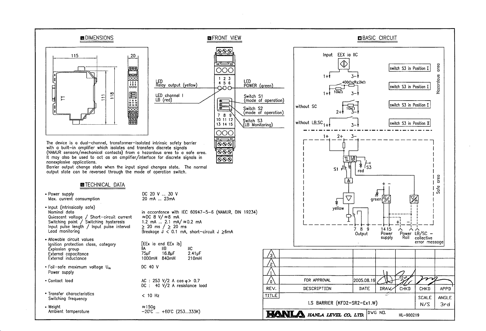
The
device
is
with a
(NAMUR
It may also
nonexplosive applications.
Barrier output change state
output state
• Power supply
Max.
• Input (Intrinsically safe)
Nominal data
Quiescent voltage I
Switching point I Switching hysteresis 1.2
Input pulse length I Input pulse interval
Lead
•
Allowable
Ignition protection class, category
Explosion group
External cagacitance
External
• Fail-safe maximum voltage
Power
• Contact load
• Transfer characteristics
Switching frequency
•
Weight
Ambient temperature
a dual-channel, transformer-isolated intrinsic safety barrier
built-in
amplifier which isolates and transfers discrete signals
sensors/mechanical contacts) from a hazardous area to a safe area.
be
used
to
act
as
can
be
when
reversed through the
I1TECHNICAL
current consumption 20
Short-circuit
monitoring
circuit values
in
uctonce 1000mH
supply
Urn
1"""",
~
~
H.
000
~
,
..
101112
13 14
IS
00c5
~
1",,,,,,,1
~
an
amplifier
linterface
the input signal changes state.
DATA
mode of operation switch.
current
LED
Relay
LED
LB
for discrete signals
DC
20
V ... 30 V
mA
...
in
accordance
RlDC
8
VI
mA
...
~
20
ms
Breakage
[EEx
ia
and
IIA
75uF
DC
40 V
AC
: 253
DC:
40
<
10
Hz
Rl150g
-20'C
... +60'C (253
output (yellow)
channel
(red)
23mA
Rl8
2.1
I
J <
liB
16.81JF
840mH 210mH
V/2
V/2
I
The
with
IEC
60947-5-6
mA
mAl
RlO.2
~
20 ms
0.1
mA,
short-circuit
EEx
ib]
IIC
2.411JF
A cos
q>
> 0.7
A resistance load
...
333K)
normal
mA
/'
in
.~.
II
= =
000
123
456
'lno
/~
~
10
11
13
14
LED
POWER
Switch
(mode of operation)
Switch
~
(mode of operation)
12
~Switch
15
(LB
000
= =
~~~
~
~
(NAMUR,
J
DIN
~6mA
19234)
(areen)
Sl
S2
S3
Monitoring)
/3\
M
M
/0\
REV.
TITLE
~
Input
EEX
ia
IIC
I
switch
1+~
400n~R:!::2kfl
1+~
without
without
SC
LB,SC 1 +l
2+
3-
~
~1
----------_._---------------------
1+
2+
3-
r---t~r-
t!
51
yellow
------------1
-u.
V'
1
!5~
*
ts~
red
&]
,£~
ill
L________
FOR
APPROVAL
DESCRIPTION
1.5
BARRIER
HANLA.
(KFD2-5R2-Exl.W)
lEVEL
co..
7 8
2005.08.19
LmJD\JG
__~~~~~~--~
9
Output
DATE
+ -
-
1415
Power
supply
\ n
~
DRA\J/
c··
NO.
I
switch
I
switch
I
switch
::~---l:
A
/J
-~
HL-900219
S3
S3
S3
S3
Power
Rail
CHKD
in
in
in
in
Position
I I
Position
I I
Position
I I
Position
n I
'i7n-
I
I
::
AA
LB~SC
co lective
error message
J
~
CHKD
SCALE
N/S
-
I
I
I
I
I
I
I
1.2
IUl
I
I
I
I
0
~
0
(I)
~
0
"E
0
N
0
:c
0
~
0
0
~
APPD
ANGLE
3rd
"""\
f-
....
~.
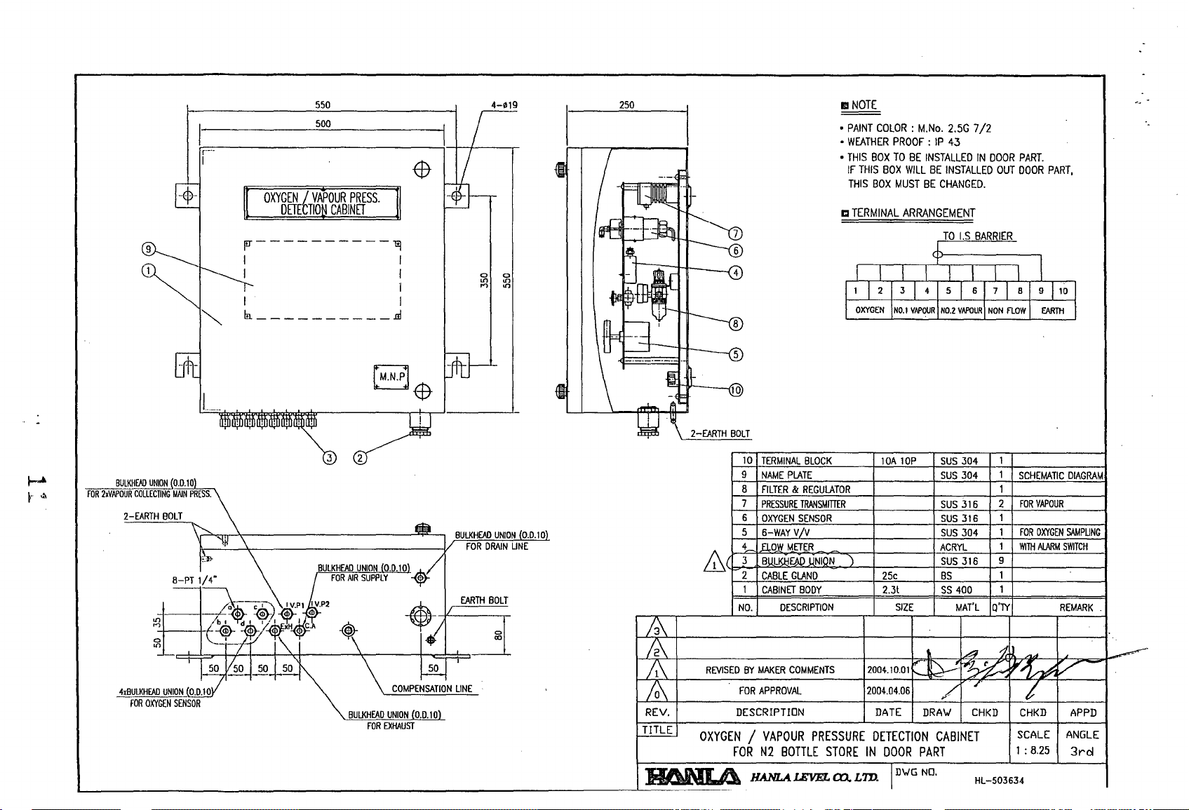
550
500
II
NOTE
•
PAINT
•
WEATHER
•
THIS
BOX
IF
THIS
THIS
BOX
COLOR:
PROOF:
TO
BOX
MUST
M.No.
BE
INSTALLED
WILL
BE
BE
2.5G
7/2
IP
43
INSTALLED
CHANGED.
IN
DOOR
OUT
PART.
DOOR
PART,
-$-
1:1
TERMINAL
jIT----------l!]
~
1
BULKHfAD
UNION
roR
,f\
2xVAPOUR
2-EARTH
(0.0.10
COLLECTING
MAIN
BOLT
on
....,
0
on
PRESS.
I I
I I
I I
In.
__________
3
m
2
I
10
BULKHEAD
UNION
FOR
DRAIN
0.0.10
UNE
&
TERMINAL
9
NAME
8
FILTER & REGULATOR
7
PRESSURE
CABLE
CABINET
NO.
BLOCK
PLATE
TRANSMITIER
GLAND
BODY
DESCRIPTION
ARRANGEMENT
lOA
lOP
25c
2.3t
SIZE
SUS
304
SUS
304
SUS
316
SUS
316
SUS
304
ACRYL
SUS
316
BS
SS
400
MAn
1
1
2
9
1
Q'TY
SCHEMATIC
FOR
FOR
WITH
DIAGRAM
VAPOUR
OXYGEN
SAMPUNG
ALARM
SWITCH
REMARK
.
L-
__________________________________________________________________
50
COMPENSATION
LINE
REV.
TITLE
-L
________
II6NI.A
REVISED
BY
MAKER
COMMENTS
FOR
APPROVAL
DESCRIPTION
OXYGEN / VAPOUR
FOR
N2
BOTTLE
__
HANLA.1EVEL
PRESSURE
STORE
ro.
LTD.
DETECTION
IN
DATE
DOOR
D~G
DRA~
CABINET
PART
NO.
CHKD
HL-S03634
CHKD
SCALE
1:
8.25
APPD
ANGLE
3rd
-$-
L,~-L
bad
____
C I
-L
__
-L
______
-L-L
__
-L
____________
~-L
________
•
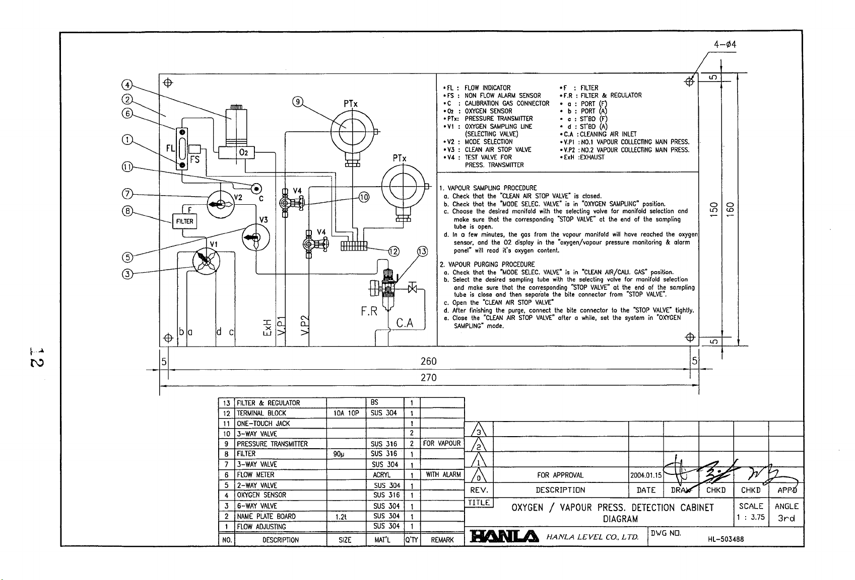
fL:
FLOW
:
NON
CALIBRATION
:
OXYGEN
PRESSURE
(SELECTING
PRESS.
SAMPLING
Check
that
Check
that
Choose
the
make
sure
tube
is
open,
In a few
sensor,
and
panel"
will
PURGING
Check
that
Select
the
and
make
tube
is
close
Open
the
After
finishing
Close
the
SAMPLING"
INDICATOR
flOW
ALARM
GAS
SENSOR
TRANSMITIER
SAMPLING
VALVE)
SELECTION
AIR
STOP
VALVE
FOR
TRANSMITTER
PROCEDURE
the
·CLEAN
the
"MODE
desired
manifold
that
the
minutes,
the
the
02
read
it's
PROCEDURE
the
"MODE
desired
sampling
sure
that
and
then
"CLEAN
AIR
the
purge,
"CLEAN
AIR
made.
SENSOR
CONNECTOR
LINE
VALVE
AIR
SELEC.
corresponding
gas
display
oxygen
SELEC.
the
corresponding
separate
STOP
connect
STOP
•
FS
• C :
•
02
•
PTx:
•
VI : OXYGEN
•
V2 : MODE
•
V3 : CLEAN
•
V4 : TEST
1.
VAPOUR
a.
b.
c.
d.
2.
VAPOUR
a.
b.
c.
d.
e.
-L
________________________________________________
STOP
VALVE"
with
from
in
the
content.
VALVE"
tube
VALVE"
VALVE"
• F :
•
F.R
• a :
• b :
• c :
• d :
•
C.A : CLEANING
•
V.Pl
•
V.P2
•
ExH
VALVE"
the
"STOP
the
vapour
·oxygen/vapaur
with
the
bite
the
after a
FILTER
:
FILTER
PORT
PORT
ST'BD
ST'BD
:
NO.1
:
NO.2
:EXHAUST
is
closed.
is
in
"OXYGEN
selecting
VALVE"
is
in
"CLEAN
the
selecting
"STOP
connector
bite
connector
while,
(F)
(Al
(F)
(A)
VAPOUR
VAPOUR
valve
at
manifold
VALVE"
set
&:
REGULATOR
AIR
INLET
COLLECTING
COLLECTING
SAMPLING"
for
manifold
the
end
will
have
pressure
AIR/CALI.
valve
for
at
the
from
"STOP
to
the
the
system
MAIN
MAIN
position.
selection
of
the
sampling
reached
monitoring
GAS"
position.
manifold
end
of
VALVE".
"STOP
VALVE"
in
PRESS.
PRESS.
and
the
oxygen
&:
alarm
selection
the
sampling
tightly.
"OXYGEN
-$-
~
4-¢4
~
a a
L[)
1---:-:::-1-
L[)
<.0
5
260
5
270
13
FILTER
&:
REGULATOR
12
TERMINAL
11
ONE
~1~0~3-=W~~=~=~~E~----~--~----~2~----~
9
PRESSURE
B
FILTER
~7~3=-W=A~X-V-AL-V~E--------~~--~~S=U~S=3~04~~I~-------1
6
FLOW
5 2
4
OXYGEN
3
6-WAX
~2-EN~A=ME~P=LA~JE~BO-A-RD------+--1.-2t--~~S~US~30~4~~I~-------1
1
FLOW
NO.
TOUCH
METER
WAX
VALVE
SENSOR
VALVE
ADJUSTING
DESCRIPTION
BLOCK
JACK
TRANSMITIER
lOA
90lJ
SIZE
lOP
BS
SUS
SUS
SUS
ACRYL
SUS
SUS
SUS
SUS
MAn
1
304
1
1
316
2
FOR
VAPOUR
316
1
1
WITH
ALARM
304 1
316 1 REV,
304
1 I
304 1
Q'N
REMARK
/\
/3\
/2\
/\
/1\
Ia\
TITLE
OXYGEN / VAPOUR
aem
FOR
APPROVAL
DESCRIPTION
A
HANLA
LEVEL
PRESS,
DIAGRAM
co.,
LTD.
2004.01.15~~
DATE
DR~
DETECTION
I
D\oIG
NO,
CHKD
CABINET
HL-503488
}7/
~
CHKD ~ APP,6
SCALE
1 : 3.75
ANGLE
3rd
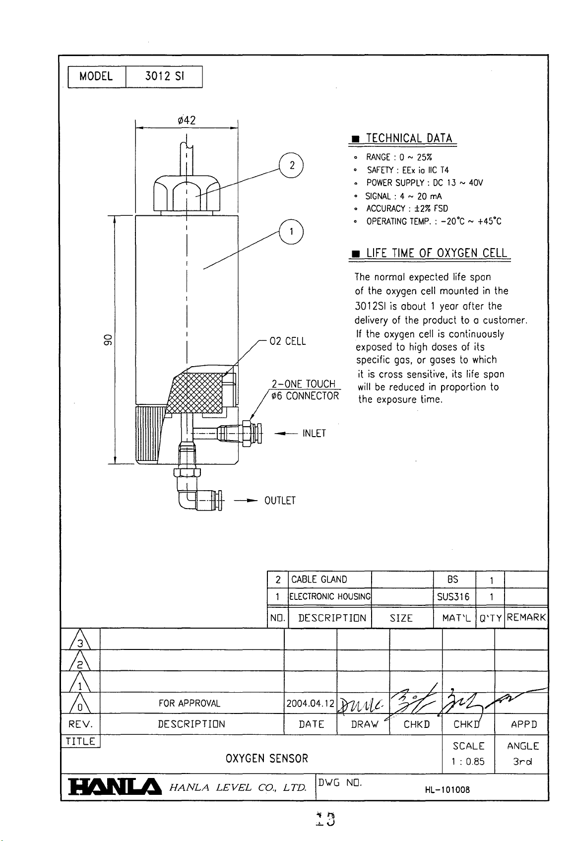
MODEL
I
I
3012
SI
¢42
I
0
(j)
-,----
{
I
J
~
~rttfY
I
I
/8
V02
./
2-0NE
9)6
-[~
"""L-
---
U
CELL
TOUCH
CONNECTOR
INLET
IX
'{'0,.
~
I
I
/
I
I
I
I
I
~
·---lttl-
TECHNICAL
•
0
RANGE
.
SAFETY : EEx
0
POWER
o
SIGNAL:
o
ACCURACY:
0
OPERATING
LIFE
•
The
normal expected life
of
the
3012S1
delivery
If
the
exposed
specific
it
is
cross sensitive, its life
will
be
the exposure time.
DATA
: 0 N
25%
io
IIC
T 4
SUPPLY:
4 N
TIME
oxygen
is
about 1
of
oxygen
to
gas,
reduced
DC
13 N 40V
20
rnA
±2%
FSD
TEMP.
: -20·C ~ +45·C
OF
OXYGEN
spon
cell mounted
year
after
the product to a customer.
cell
is
continuously
high
doses
of its
or
gases
in
to
which
proportion to
CELL
in
the
the
span
-'----
f
.,-J-,
J l-+-!
I
--
~
/i\
/2\
/1\
FOR
10\
REV. DESCRIPTION
TITLE
APPROVAL
--
OUTLET
OXYGEN
CABLE
2
ELECTRONIC
1
NO.
DESCRIPTION
2004.04.12
DATE
SENSOR
GLAND
HOUSING
SIZE
....,
JrzttLt~
DRAV ""-
V%-
CHKD
BS
SUS316
MArL
~
/
~i,/
CHKr1
SCALE
1 : 0.85
1
1
Q'TY
~
REMARK
-
APPD
ANGLE
3rcl
IIf\NLA
HANLA
LEVEL
co.,
LTD.
IDVG
NO.
HL-101008
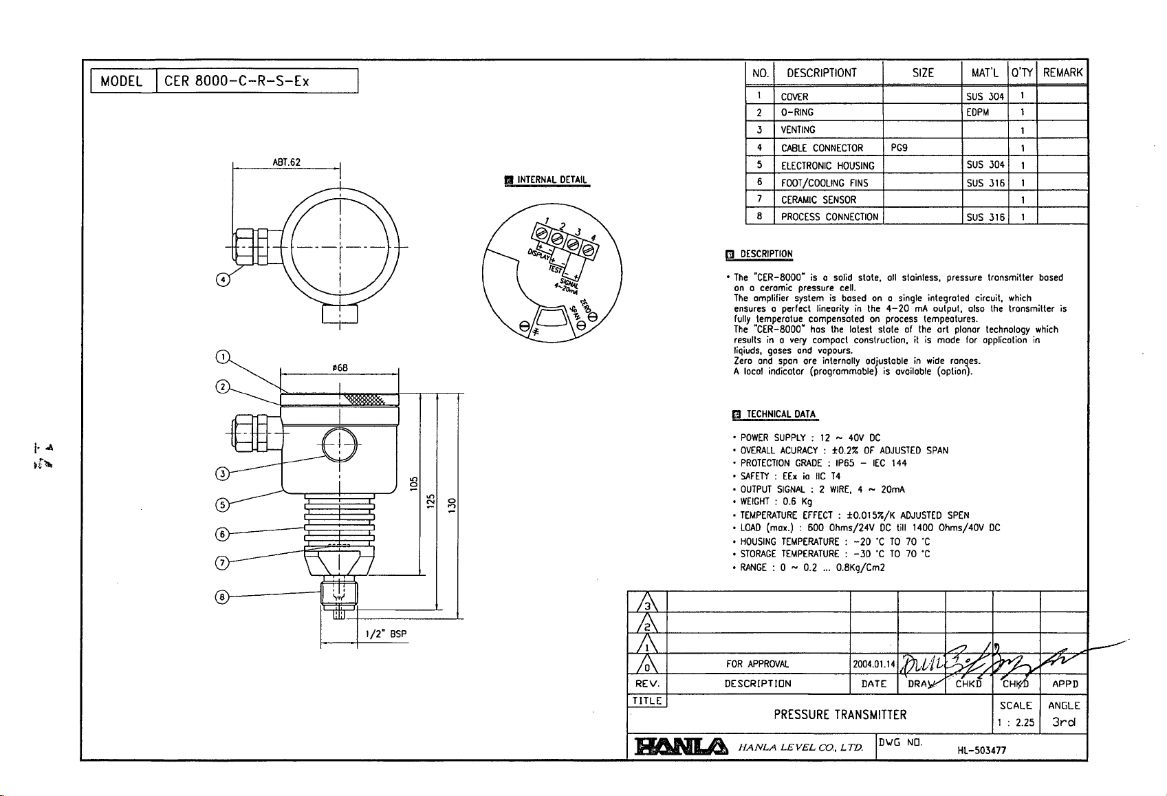
MODEL
I
CER
8000-C-R-S-Ex
I
~
cv---
ABT.62
-
~~
4
~-
5
6
7
8
I
-L
,
I
,
I
---r---rt-
,
I
,
cp
068
I
~
I
r
£9-
f.--i
i
- -
~177
tttt1
W
iF.#=I
w:J.
1/2"
SSP
.,.,
a
-
.,.,
N
-
a
...,
-
Q'TY
DESCRIPTIONT SIZE MAT'L
NO.
1
COVER
O-RING
2
VENTING
3
FINS
state,
on a single
in
the
on
DC
OF
ADJUSTED
4 ~ 20mA
DC
-20
'C
'C
PGg
all
stainless,
4-20
process
of
is
available
144
ADJUSTED
till
TO
70
TO
70
mA
tempeotures.
the
is
in
1400
'C
'C
4
CABLE
CONNECTOR
5
ELECTRONIC
II
INTERNAL
[
e~
DETAIL
1
2
00
J
DlsPi:it-
00
Tts,-
- +
.~
1>
D\~e
e
6
FOOT/COOLING
7
CERAMIC
8
PROCESS
.,
m
DESCRIPTION
I
•
The
"CER-8000·
on a ceramic
The
amplifier
ensures
a perfect linearity
fully
temperotue
The
·CER-8000·
results
in a very
liqiuds,
gases
Zero
and
A
e
•
•
•
•
•
•
•
•
•
•
•
span
local
indicator {programmable
TECHNICAL
POWER
SUPPLY:
OVERALL
ACURACY : ±O.2%
PROTECTION
SAFETY : EEx
OUTPUT
SIGNAL
WEIGHT
: 0.6
TEMPERATURE
LOAD
(max.) : 600 Ohms/24V
HOUSING
TEMPERATURE:
STORAGE
TEMPERATURE : -30
RANGE
: 0 ~ 0.2
system
DATA
GRADE : IP65 -IEC
HOUSING
SENSOR
CONNECTION
is a solid
pressure
and
cell.
is
based
compensated
has
the
latest state
compact construction, it
va
pours.
are
internally ad/ustable
12 ~ 40V
io
IIC
T 4
: 2
WIRE,
Kg
EFFECT:
±O.OI5%/K
...
0.8Kg/Cm2
SUS
304
EDPM
SUS
304
SUS
316 1
SUS
316 1
pressure
integrated circuit,
output,
art planar
mode
wide
(option.
SPAN
Ohms/40V
transmitter
also
the
technology
for application
ran~es.
SPEN
DC
REMARK
1
1
1
1
1
1
based
which
transmitter
which
in
is
~
/2\
/1\
FOR
/0\
REV. DESCRIPTION DATE DRAj"V'
TITLE
APPROVAL
PRESSURE
II6NLI.i
HANLA
LEVEL
2004.01.14
TRANSMITTER
LTD.
ID"'G
Co.,
1:t)Ltlit
NO.
II')
..-2.
~ ~
CHKt
'cH~
SCALE
1 : 2.25
HL-503477
~
APPD
ANGLE
3rcl
~
A'
..
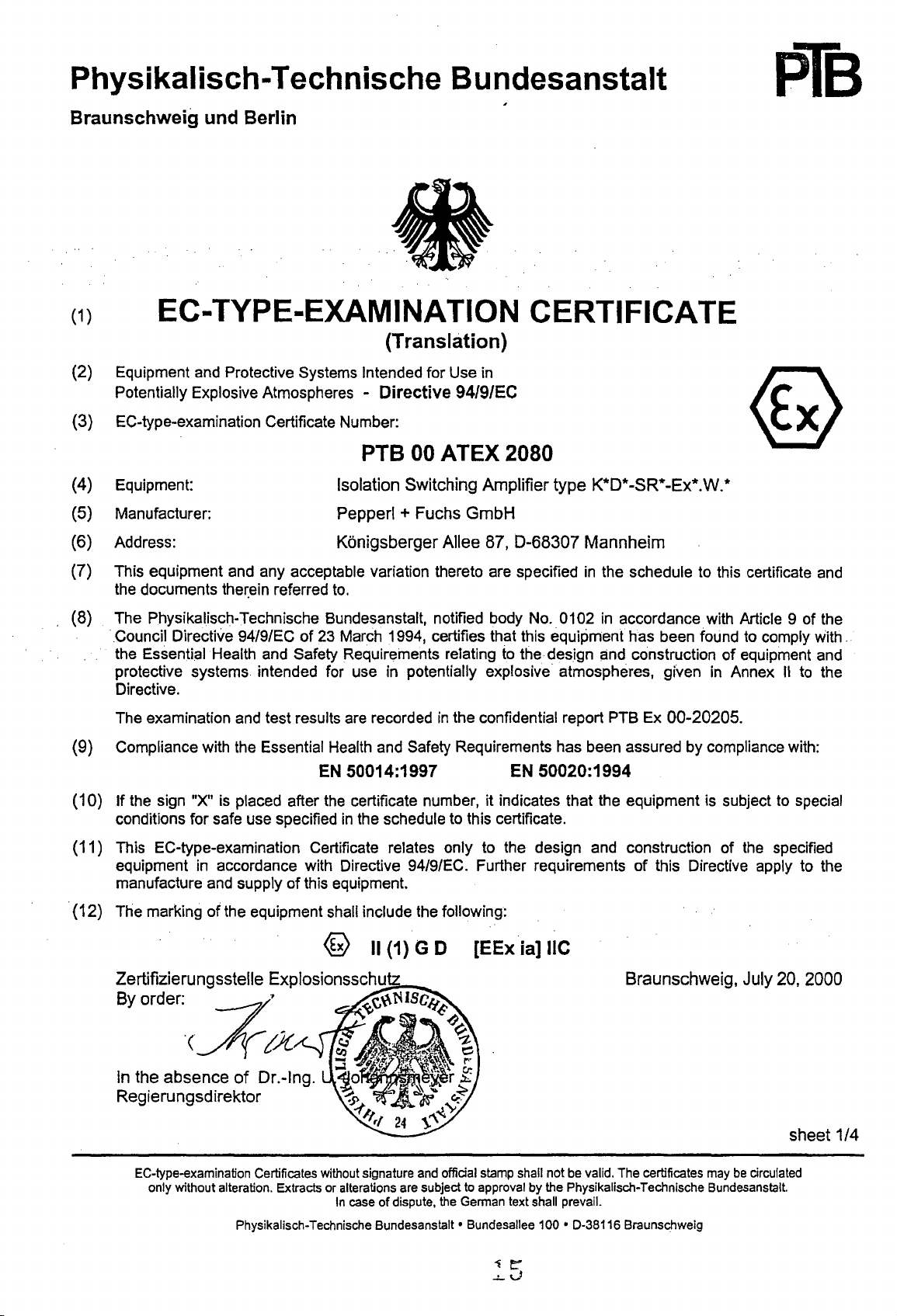
Physikalisch-Tech n ische B u ndesanstalt
Braunschweig und Berlin
(1) EC-TYPE-EXAMINATION CERTIFICATE
(Translation)
(2)
Equipment and Protective Systems Intended for Use in
Potentially Explosive Atmospheres -
(3)
EC-type-examination Certificate Number:
Directive
94/9/EC
pTB
PTe
(4)
Equipment:
(5)
Manufacturer:
(6)
Address:
(7)
This equipment and any acceptable variation thereto are specified
the documents
(8)
The Physikalisch-Technische Bundesanstalt, notified body No. 0102
. Council Directive 94/9/EC
the Essential Health and Safety Requirements relating to the design and construction
protective systems intended for use in potentially explosive atmospheres, given in Annex
Directive.
The examination and test results are recorded
the~ein
referred
Isolation
Pepperl + Fuchs
Konigsberger
to.
of
23 March 1994, certifies that this equipment
00
ATEX 2080
Switching
GmbH
Allee
in
the confidential report PTB Ex
Amplifier
87,
D-68307
type
Mannheim
in
K*O*-SR
the schedule to this certificate and
in
...
-Ex
accordance with Article 9 of the
has
been found to comply with.
00-20205.
(9) Compliance with the Essential Health and Safety Requirements has been assured
EN
50014:1997
(10)
If
the sign "X" is placed after the certificate number, it indicates that the equipment is subject to special
conditions for safe use specified
(11)
This EC-type-examination Certificate relates only to the design and construction
equipment in accordance with Directive
manufacture and supply
of
in
the schedule to this certificate.
this equipment.
94/9/EC. Further requirements
EN
50020:1994
of
this Directive apply to the
....
W.*
of
equipment and
by
compliance with:
of
the specified
II
to the
.
(12)
The marking
Zertifizierungsstelle
By
order:
of
the equipment shall include the following:
----/'
®
Explosionssch.-u
~
II
(1)
___
G 0
[EEx
ia]
lie
Braunschweig,
'(//7jI/C
In
the
absence
Regierungsdirektor
EC-type-examination Certificates without signature and official stamp shall not be valid. The certificates may
only without alteration. Extracts or alterations are subject to approval by the Physikalisch-Technische Bundesanstalt.
of
Dr.-Ing.
In
case
of
dispute, the German text shall prevail.
Physikalisch-Technische Bundesanstalt·
Bundesallee
100'
D-38116 Braunschweig
July
be
circulated
20,
sheet
2000
1/4
Physikalisch-Techn ische B u ndesa nstalt
Braunschweig und Berlin
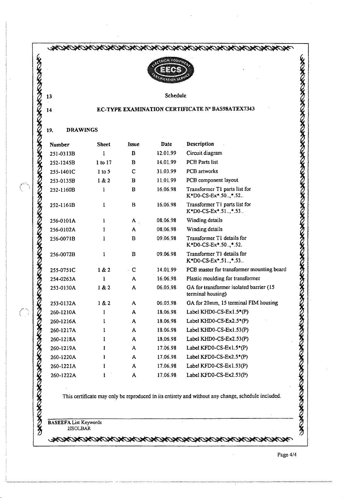
(13) S C H E D U L E
pTB
(14)
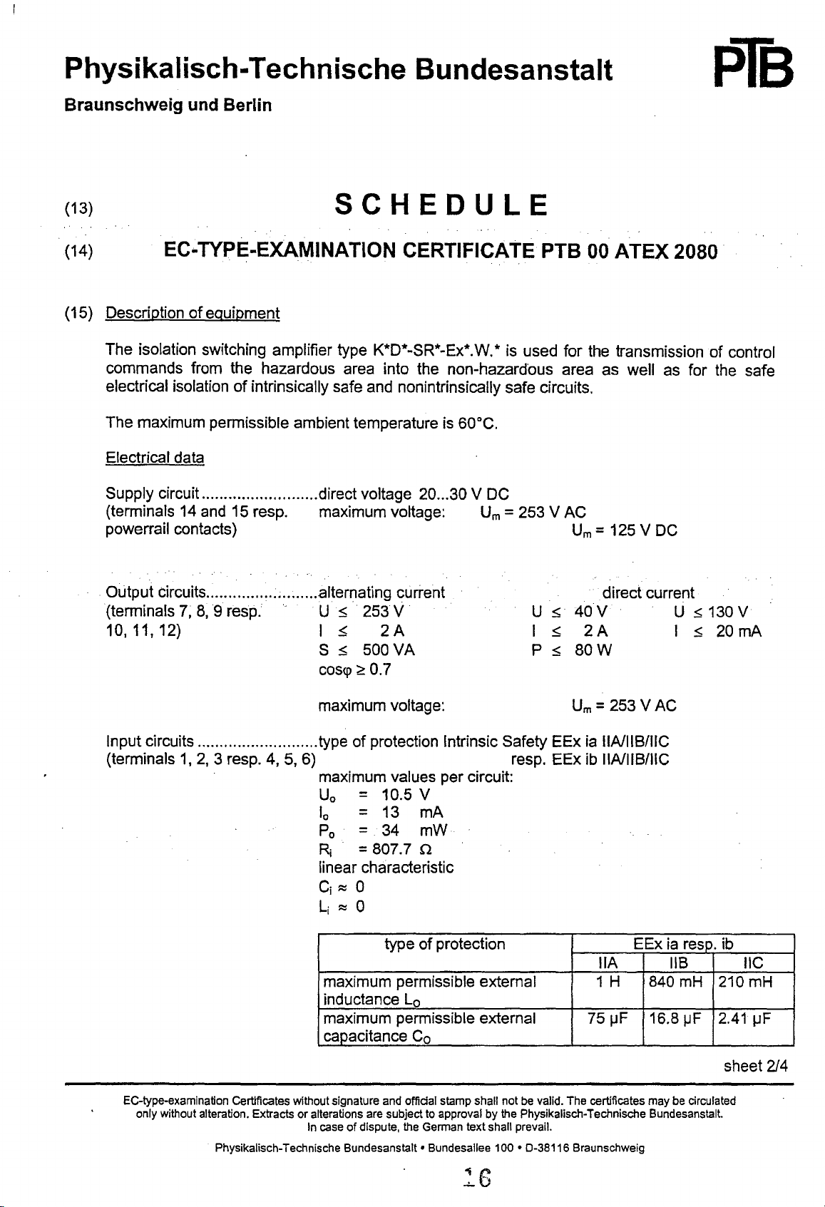
(15) Description
The isolation switching amplifier type K*D*-SR*-Ex*.W.* is used for the transmission of control
commands from the hazardous area into the non-hazardous area as well as for the safe
electrical isolation
The maximum permissible ambient temperature is
Electrical data
Supply circuit.. ........................ direct voltage
(terminals
powerrail contacts)
Output circuits ...............
(terminals
10,11,12)
EC
..
TYPE-EXAMINATION CERTIFICATE PTS
of
equipment
of
intrinsically safe and nonintrinsically safe circuits.
60°C.
20
...
30 V DC
14
and 15 resp. maximum voltage:
~
......... .alternating current
7,8,9
resp.
U~
I
S
cosq> ~ 0.7
~
~
253 V
2A
500
VA
Urn
= 253 V AC
Urn
U ~ 40
I
~
2A
P 5
80W
00
ATEX 2080
= 125 V DC
direct current
V U 5 130 V
I 5
20
mA
maximum voltage:
Input circuits ........................... type
(terminals
EC-type-examination Certificates without signature and offidal stamp shall not be valid. The certificates may be circulated
only without alteration. Extracts
1,
2,
3 resp. 4, 5, 6) resp. EEx
or
In
Physikalisch-Technische
of
protection Intrinsic Safety EEx
maximum values per circuit:
U
= 10.5 V
o
10
= 13
Po
= 34
R
= 807.7 n
j
linear characteristic
j
C
:::::
°
Li
:::::
0
maximum permissible external 1 H
inductance
maximum permissible external
caJ~.acitance
alterations are subject to approval by the Physikalisch-Technische Bundesanstalt.
case
of
dispute, the German text shall prevail.
Bundesanstalt· Bundesallee 100 • 0-38116 Braunschweig
type
Lo
mA
mW
of
protection EEx
Co
Urn
= 253 V AC
ia
!IA1HBIIIC
ib
1IA1I1BIIIC
itA
75IJF 16.8
ia
resp. ib
liB IIC
840
mH
IJF
210mH
2.41
lJF
sheet
214

Physikalisch-Technische Bundesanstalt
Braunschweig und Berlin
pTB
SCHEDULE TO EC-TYPE-EXAMINATION CERTIFICATE
In
the presence
in
the intrinsically safe input circuit, the maximum permissible
external capacitances and
"ia" are to be taken from the following table. .
maximum permissible external inductance Lo
maximum permissible external
When both intrinsically safe input circuits are interconnected, the
following maximum values result:
U
= 10.5 V
o
10
= 26
Po
= 68
Ri
= 403.9 n
linear characteristic
C
~
0
i
Li
~
0
of
concentrated capacitances and/or inductances
type
of
protection
mA
mW
PTB 00 ATEX 2080
inductances·
ca~acitance
for
circuits
Co
of
liB
7mH
2.1
category
EExia
3mH
I1F
620 nF
IIC
In the presence
in the interconnnected intrinsically safe input circuits, the
maximum permissible external capacitances and inductances for
circuits
The intrinsically safe input circuits are safely
peak value
(16) Test report
of
the nominal voltage
PTa
Ex 00-20205
type
of
protection
EEx
IlA
maximum permissible external 420 mH
inductance
maximum permissible external
ca~acitance
maximum permissible external inductance Lo
maximum permissible external capacitance Co
of
of
category
375
Lo
~F
75
Co
of
concentrated capacitances and/or inductances
nia"
are to be taken from the following table.
type
of
protection EEx
electrically isolated from all other circuits up to a
V.
ia resp. ib
liB
210 mH
16.8
~F
liB
7mH
IIC
52mH
2.41jJF
ia
IIC
3mH
2;11.JF 590 nF
(17) Special conditions for safe use
None
EC·type-examination Certificates without signature and official stamp shall not be valid. The certificates may be circulated
only without alteration. Extracts or alterations are subject to approval by the Physikalisch.Technische Bundesanstalt.
In
Physikalisch·Technische Bundesanstalt· Bundesallee
case of dispute, the German text shall prevail.
100·
0·38116 Braunschweig
sheet
3/4
Physikalisch-Technische Bundesanstalt
Braunschweig und Berlin
pTe
SCHEDULE TO EC·TYPE·EXAMINATION CERTIFICATE
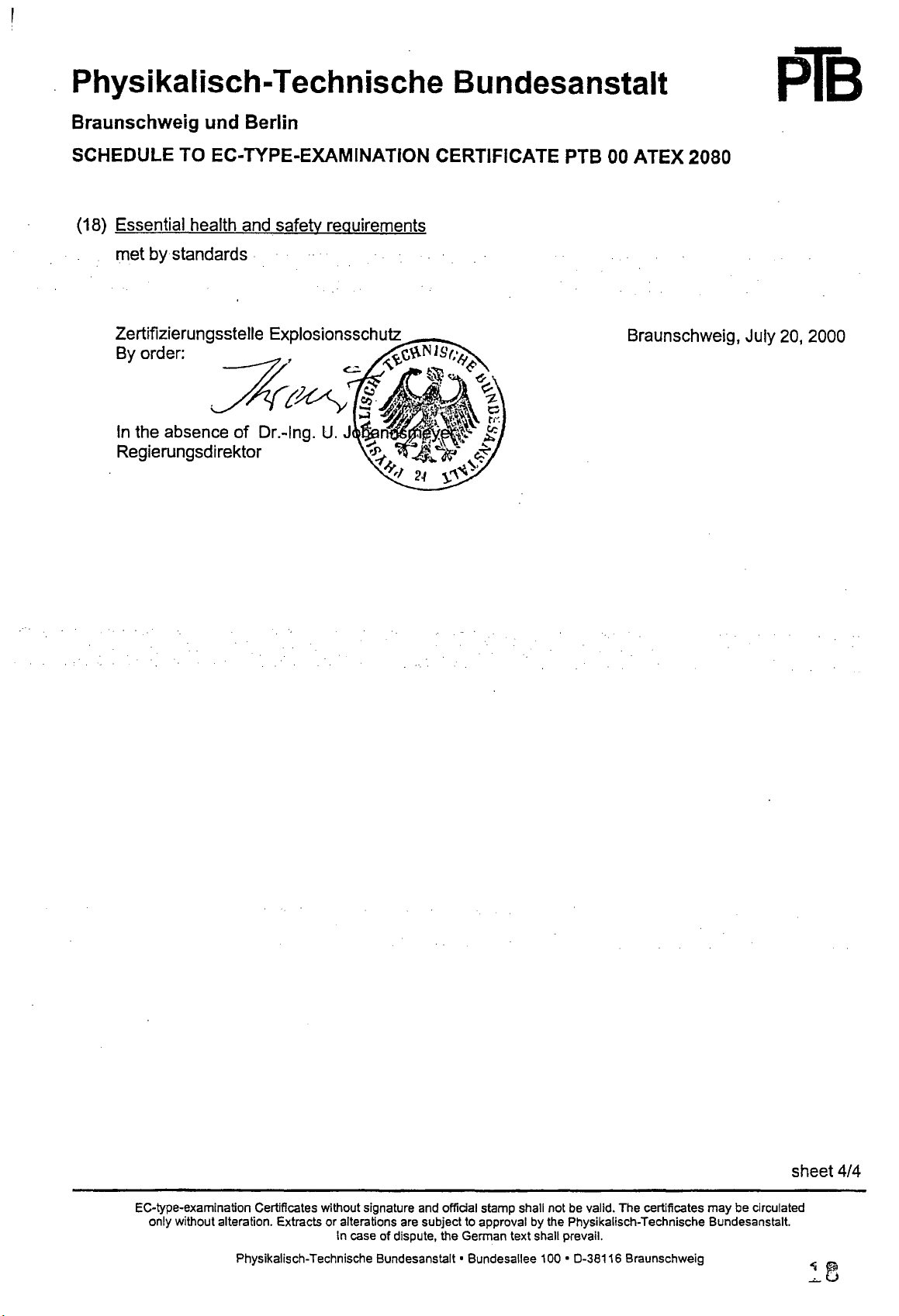
(18) Essential health
by
met
standards
and
safety requirements
PTB 00 ATEX 2080
Braunschweig, July
20,
2000
EC-type-examination Certificates without signature and official stamp shall not be valid. The certificates
only without alteration. Extracts
Physikalisch-Technische
or
alterations are subject to approval by the Physikalisch-Technische Bundesanstalt.
In case
of
dispute, the German text shall prevail.
Bundesanstalt·
Bundesallee
100'
0-38116
Braunschweig
may
be circulated
sheet 4/4

1
EC-TYPE EXAMINATION CERTIFICATE
2
Equipment
or
Protective System
Intended
in Potentially Explosive Atmospheres
Directive 94/9fEC
J
EC-Type Examination Certificate Number :
4 Equipment or Protective
System:
TAANSF()MtER. ISOLA
BAS98ATEX7343
SEPARATOR TYPE K*DO-CS-Ex".S*
5 Manufacturer: PE}lPERL + FUCHS
6 Address:
7 This equipment or protective
to
Oldham,
Lanes,
OLI
system
this certificate and the documents therein refem:d
4EL
GB
and
LIMITED
any
acceptable variation thereto is specified in the schedule
to.
8 The Electrical Equipment Certification Service, notified
Article 9 of the Council Directive
protective system has
relating
to
the design and construction of equipment and protective systems intended for
potentially explosive atmospheres given in Annex
The examination and
9 Compliance with
except in respect
10 If the sign
"X"
system is subject
11
This EC-TYPE EXAMINATION CERTIFICATE relates
specified equipment or protective
been found
test
results are recorded
the
Essential Health and Safety Requirements has been assured
EN
of
those requirements listed at item
is
placed after the certificate number, it indicates that the equipment or protective
tei
special conditions for safe
94/9IEC of
to
comply
98(C)0611
50014: 1997
system,
23
March
'with
the Essential Health and Safety Requirements
II
to
the Directive:
in
confidential Report N°
dated
29
April
1999
EN
50020: 1994
18
of the Schedule,
use
specified
If
applicable, further requirements
the manufacture and supply of this equipment or protective
for
use
TEn
LOOP
POWERED CURRENT
body
number
1994,
in
the schedule to this certificate.
only
to
the design and construction of the
600
in accordance with
certifies that this equipment or
by
compliance with:
of
this Directive apply
system,
use
in
to
::.
••
•••• • .••••••••••••
12 The marking
G
This
certificate may
File
No:
EEeS
0807/02/168
This certificate
Equipment
rna • be
CERTIATEX\EQUIP\CATJ-'!\P. Issue
....
• •• •
••
.....
.. ..
•••
.....
i.
CertificatIon
used
in articular industrieS or
~
H5E
HullltkS&1cty
E",c".lh·~
•• • ................ -••
of
the equipment or protective
U[l}G
only
be reproduced
!1anted subject to the general conditions
Service.
It
dOeS
not
necessarily indicate thal the apparatus
circil111stances.
Electn(:ai Equlp!I'ent cei-ttftcation
'"
...............................
Harpur Hill,
I,
Dated September
Tel: 01298 28000 Fax:
~.~,~,
••
,~
..... -•••.•
",
.••
in
He~lth
Buxton,
".'~.'.'~~_'~""."'~.'.'.'.'
andSat'eiyExe<:u1ive
Derbyshire:
199&
••• : ••••••••••••••••••.•••••.••••••••••••••••••••.••••••••••••••••••••••••••••••••••••••••••••••••••••••••••••••••.•• : ••.•.••••••••••••• : •••.
system
shall include the following:-
its entirety and without
of
the
Electrical
Service
SKI7
9JN. United Kingdom
0129&
28244
any
change, schedule included,
f/
IMCLEARE
DIRECTOR
7 July 1999
-: •.••.•.•.•.•
'.
-:" ...........
~~~.;.;.;-~-~
Page
114
.~
...............................................................................................
:-:-~:-'o;>:---""
•••
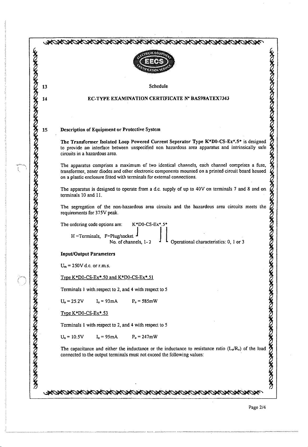
13 Schedule
.....
14
15
Description
The
TransfonnerIsolated
to provide
EC-TYPE
of
Equipineilt
an
interface between unspecified non hazardous area apparatus and intrinsically safe
EXAMINATION
or
Protective System
Loop
Powered
CERTIFICATE
Current
Seperator
Ne
BAS98ATEX7343
Type
K*DO-CS-Ex*.S* is designed
circuits in a hazardous area.
.;
..
~.,
...
The apparatus comprises a maximum of two identical channels, each channel comprises a fuse,
transformer, zener diodes and other electronic components mounted
on a plastic enclosure fitted
The
apparatus is designed to operate from a d.c. supply
terminals
The
10
and
segregation
11.
of
requirements for 375V
The
ordering code options are: K
with terminals for external connections.
of
up
the non-hazardous area circuits and the hazardous area circuits meets the
peak.
...
DO-CS-Ex
....
5*
on
a printed circuit board housed
to
40V on terminals 7 and 8 and
on
H =TerminaIs, F=Pluglsocket 1 J l
No.
of
channels,
1-
2 Operational characteristics: 0, I
or
3
Input/Output
Urn
= HOV d.c.
Type
K*DO-CS-Ex*.50
Terminals 1 with respect to 2,
Uo=2S.2V
Type
K*DO-CS-Ex*.53
Terminals 1 with respect
U
= lO.5V
o
The
capaCitance and either the inductance or the inductance to resistance ratio
connected to the output terminals
Parameters
or
r.m.s.
and
10
= 93mA
Io= 95mA
K*DO-CS-Ex
and
4 with respect to 5
Po= 585mW
to
2,
and 4 with respect
Po=
must not exceed the following values:
....
51
247mW
to
5
(LJR,)
of
the load
Page
2/4
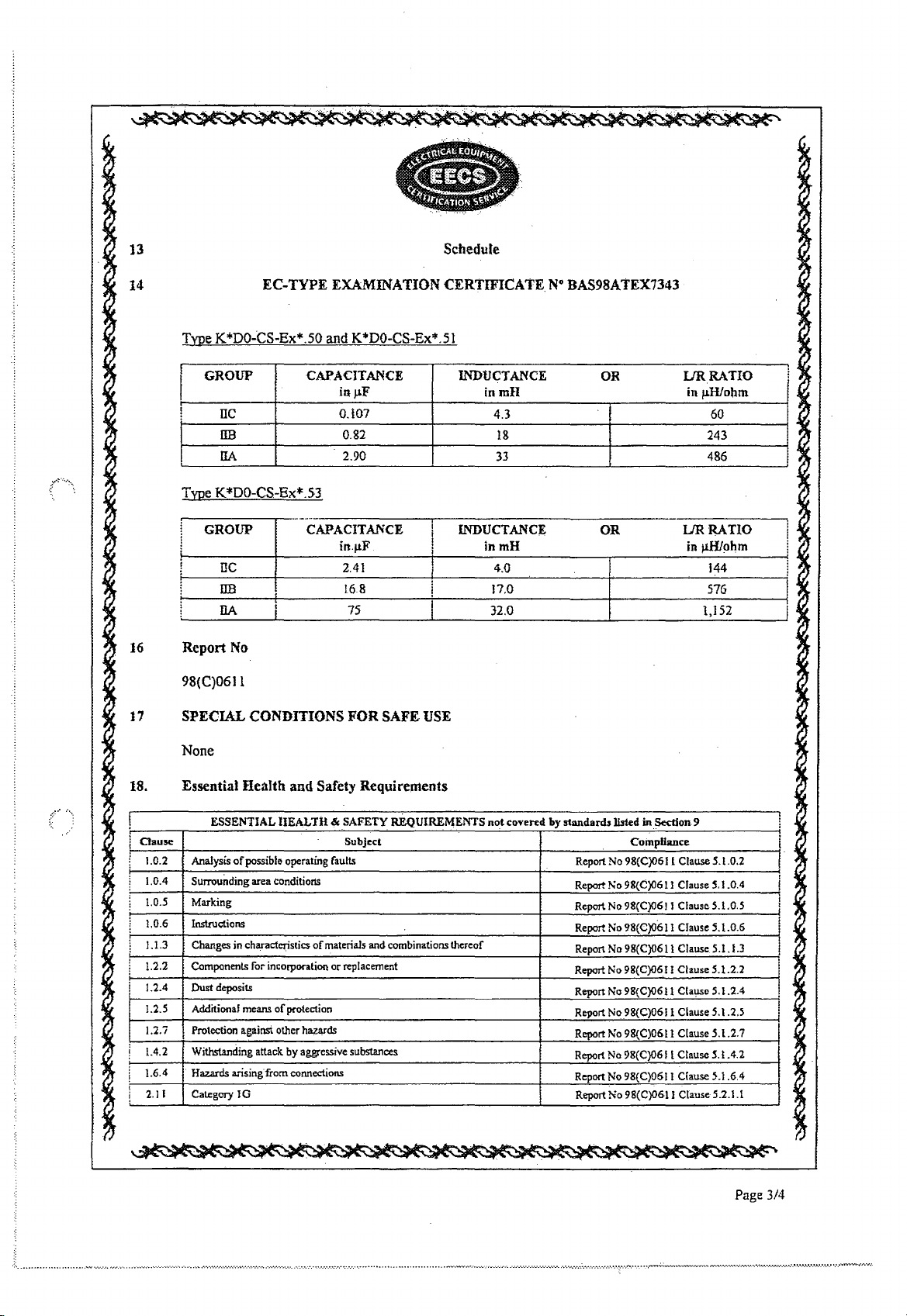
]3
••••••••••••••
.
11",
•
Schedule
14
16
17
EC-TYPE EXAMINATION CERTIFICATE
Type
K*DO~CS-Ex*.50
GROUP
I
TIC
!
lIB
ITA
Type
K*DO-CS-Ex*.53
GROUP
1
DC
!
DB
IlA
Report
No
I
I
and
K*DO-CS-Ex*.SI
CAPACITANCE
iltllF
0.\07
0.82
2.90
.
_---
CAPACITANCE
inllF
2.41
1.68
75
98(C)061l
SPECIAL CONDITIONS FOR SAFE
INDUCTANCE
INDUCTANCE
i
USE
N°
BAS98ATEX7343
OR
inmH
4.3
18
33
OR
inmH
4.0
17.0 576
IJRRATIO
in
IJRRATlO
in
).lHIohm
n.o
JlHlohm
60
243
486
144
1,152
.
I
:
J
I
I
None
18
. Essential Health
.{.,
aause
1.0.2 Analysis
1.0.4 Surrounding area conditiorts
1.0.5
1.0.6 Instructions
1.1.3
1.2.2 Components for inco!pOfation or replacement
1.2.4
1.2.5
1.2.7 I Protection against other
1.4.2
1.6.4
2.1
I Category
ESSENTIAL
of
Marking
Changes in characteristics
Dust
deposits
Additionaf means
Withstanding
Hazards arisingfrom connections
JG
and
Safety Requirements
lIEALTH
possible operating faults
of
attack
&.
SAFETY REQUIREMENTS
Subject
of
materials and combinations thereof
protection
ha<:ards
by
aggressive substances
not
covered by standards listed
Report No 98(C)0611 Clause
Report No 98(C)0611 Clause S.I.O.4
Report No
Report
Repon
Report No 98(C)061 J Clause 5.1.2.2
Report No 98(C)0611
Report No
Report No 98(C)0611 Clause 5.1.2.7
Report No 98(C)06 I I Clause
Report No
Report
in
Section 9
CompUance
5.1.0.2
98(C)0611
No 98(C)06J J Clause 5.1.0.6
No 98(C)0611 Clause
98(C)0611 Clause 5.1.2.5
98(C)06tJ
No
98(C)06J J Clause 5.2.1.1
Claus~
5.1.0.5
5.U.3
Clause 5.1.2.4
5.
t .4.2
Clause
~.J.6.4
Page 3/4
J
J
I
i
I
!
I
I
!
I
-
13 Schedule
14
19.
Number
DRAWINGS
EC-TYFE
Sheet
251-03138
252-12458
255-1401C
253-01358
1 to
1105
1&2
252-11608
252-1161B 1
256-0101A
256-0102A
256-00718
256-0072B
255-0751C
1&2
254-0263A 1
253-0130A J & 2
253-0132A
I & 2
260-1210A
216A
260-1
260-1217A
260-12J8A
260-1219A
260-1220A
260-1221A
260-1242A
EXAMINATION
Issue
17
B
8
C
B
B
B
A
A
B
CERTIFICATE
Date
12.01.99
14.01.99
31.03.99
11.01.99
16.06.98
Description
Circuit diagram
PCB Parts
PCB
PCB
Transformer T1 parts list for
K*DO-CS-Ex*.50
16.06.98
Transformer T I parts list for
K*DO-CS-Ex*
08.06.98
08.06.98
09~O6.98
Winding details
Winding details
Transformer T 1 details for
N° BAS98ATEX1343
list
artworks
component layout
..•
*.52
.51
... *.53 ..
..
K*DO-CS-Ex*.50 .. ,*.52.
1
B
·C
A
A
09.06.98
14.01.99
16.06.98
06.05.98
Transformer TJ details for
K*DO-CS-Ex*.51
PCB
master for transformer mounting board
Plastic
moulding for transformer
..
, *.53..
GA for transformer isolated barrier (IS
terminal housing)
GA
for
20mm.
15
A
A
A
A
A
A
A
A
A
06.05.98
18.06.98
18.06.98
18.06.98
18.06.98
17.06.98
17.06.98
17.06.98
17.06.98
terminal
Label KHDO-CS-ExI.5*(P)
Label KHDO-CS-Ex2.5*(P)
Label KHDO-CS-ExL53(p)
Label KHDO-CS-Ex2.53(p)
Label KFDO-CS-Ex1.5"'(P)
Label KFDO-CS-Ex2.5"'(p)
Label KFDO-CS-Ex1.53(P)
Label KFDO-CS-Ex2.53(p)
FIM
housing
This certificate may only
BASEEFA List Keywords
2ISOLBAR
be
reproduced in its entirety
.......... -...
",
.................. . .............
and
without any change, schedule included.
"'~~"~~"'''''''.'.'
.....
~~.'~.'...
.
.... ' .........
-.-........................
.
............•......•....................
;
.......•.•.•.•.
,
....
,
•..•...
Page 4/4
,
....
,.
','
.....
-:-~
.................. ~ ..................................................................
;
....•.•.....
-:.:.

1 SUPPLEMENTARY EC-TYPE EXAMINATION CERTIFICATE
2
Equipw~nt
~r
Protective
.
iDPot~n:ti~iy
¢jpIQsive
System Intended for use
atniospb¢res
Ditectlve94/9/EC
3 Supplementary EC-TypeExantirultion certificate Number: BAS98ATEX7343/1X
4 Equipment
5 Manufacturer:
6 Address: Oldbam,
7 This supplementary certificate
apply
speCification set out
Schedule
This Supplementary Certificate shall
or
Ptotectie System:
PEPptRL+roCliSGB
to
equiprneritor
attached
TRANSFQ~RISOLATED
8EP
ARAtOkTYPEK"'DO-CS':Ex'"
Unca.shireiOL14EL
~ends
to
in
this
protective
the
Sc~¢dJIle.
certificate
systeIll,S
of
and·
be
LOOP POWERED CURRENT
.5'"
LIMITED
EC-Type Exantination Certificate No. BAS98ATEX7343
d.esigned
tIl.~
said· CertifiCate but having anyvarhltions Specified
the:
dOCUIIientstherein
held
with
and
constructetf>
referred
to.
the original Certificate.
in
accordance
with.
in
to
the
the
This
certificate may only
. File
No:
EECS
0807/021168
This.
certificate.
EqUlPmented~~~ti0ln
rna
00
CERTIATEX\EQUIP\CATl-21S, Issue
is~tl:d
lis
In
..
~
HSE
K~.ltk
...
s..tefJ'
..........
~ubjeoit
S~d
..
uCU
ar
iii
ustncs
be
reproduced
to
ce
.diogeileral
..
~t
~09I.t\C)t
~Iy
or
Citcti.ihstaIiC. .
Harpur
Hill, Buxton,
1,
Dated September 1998
in
its entirety
~~cIitiOllSofthe
mdlcate that the apparatus
E1ediic:ai
Tel:
J!;qWPDlfJlt
Health
DerbySJiire.
01298
2$000
and
Safety Executive
__
.. _ ....•• _ ••
and
without any change, schedule included .
El~ca1
Certl1ication Service
SK17
!lIN.
Fax;
01298 28244
_.
••. . . . ••
•.
_.
• ..................... ~
United
Kingdom
....... ~ .. .-.......
).·
..
:·0·.··
.... · ..
··
..
...
.
.
.'
18d
?;T
{!
...
".
"
..
: ..
:.:;
".
................
"
... -.....
...
.
1
MCLEARE
DIRECTOR
20 June 2000
-::-
;»
.
.
.
to
Page 1/2
~...................
..,
......•.•... _ .....................................................
: ••• '.' ••.••••
·~~·_,
.....
·~.·~h·.·.·.~·.·.·.·.
.
.....
',"
............•. -... -.•..
,.

13
Scbedule
14 SUPPLEMENTARY
Description
VARIATION
To permit D to
Report
OO(C)0470
No.
oqhe
dated
Variation to
1.1
be
included
12
June 2000 held on file
Special Conditions ForSa(e
1.
If
the
IS
outpuUs connected
EC-
TYPE EXAMINATION CERTIFICA
the
Eqilipmej}t
in
the apparatus marking, i.e.Gn (1)
uSe
to
an
apparatus
must be certified 'D'.
Essential Health mtd Safety Requirements
See
original certificate.
DRAWINGS
ot
PrOtective
No.
EECS 0807/02/175
USed
in
TE
N"BAS98J\tEX734~1IX
System
GD,
and oilier minor changes
the presence of combustible dust, then
to
the label.
that
apparatus
Number Sbeet Issue
260-1210B
260-1216B
260-1217B
260-1218B
260-1219B 1
260-12ioB
260·122lB
260-1222B
This certificate
may
1
1
1
1
1
1
only be reproduced in its entirety and without
B
B
B
B
B
B
B
B
Date
28.2.00
29.2.00
29.2.00
29.2.00
29.2.00
29.2.00
29.2.00
29.2.00
Description
Label KHDO-'CS-Ex1.50
Labd KHDO-'CS-Ex2.50
Label KHDO-'CS-Exl.53
Label
KHDO-CS~Ex2.53
Label KFDO-CS-Ex1.50
Label
KFDO-CS~Ex2.S0
Label KFDO-CS-ExLS3
Label KFDO-'CS-Ex2.53
any
change, schedule included.
Page
2/2
.. -..............................................
-
.....
"."
...............
~
..
~~~
... ~ .....
~.,.~
............... -................•.•.•
:
•.•.
'-
...•......•........
'.'
...........
,
...
~
..
~~~,
.'.~
.......
...
 Loading...