

Page 1
Index revision : C - November 2017 1 7030
User manual
SAMES KREMLIN SAS - 13, Chemin de Malacher - 38240 MEYLAN - FRANCE
Tel. 33 (0)4 76 41 60 60 - www.sames-kremlin.com
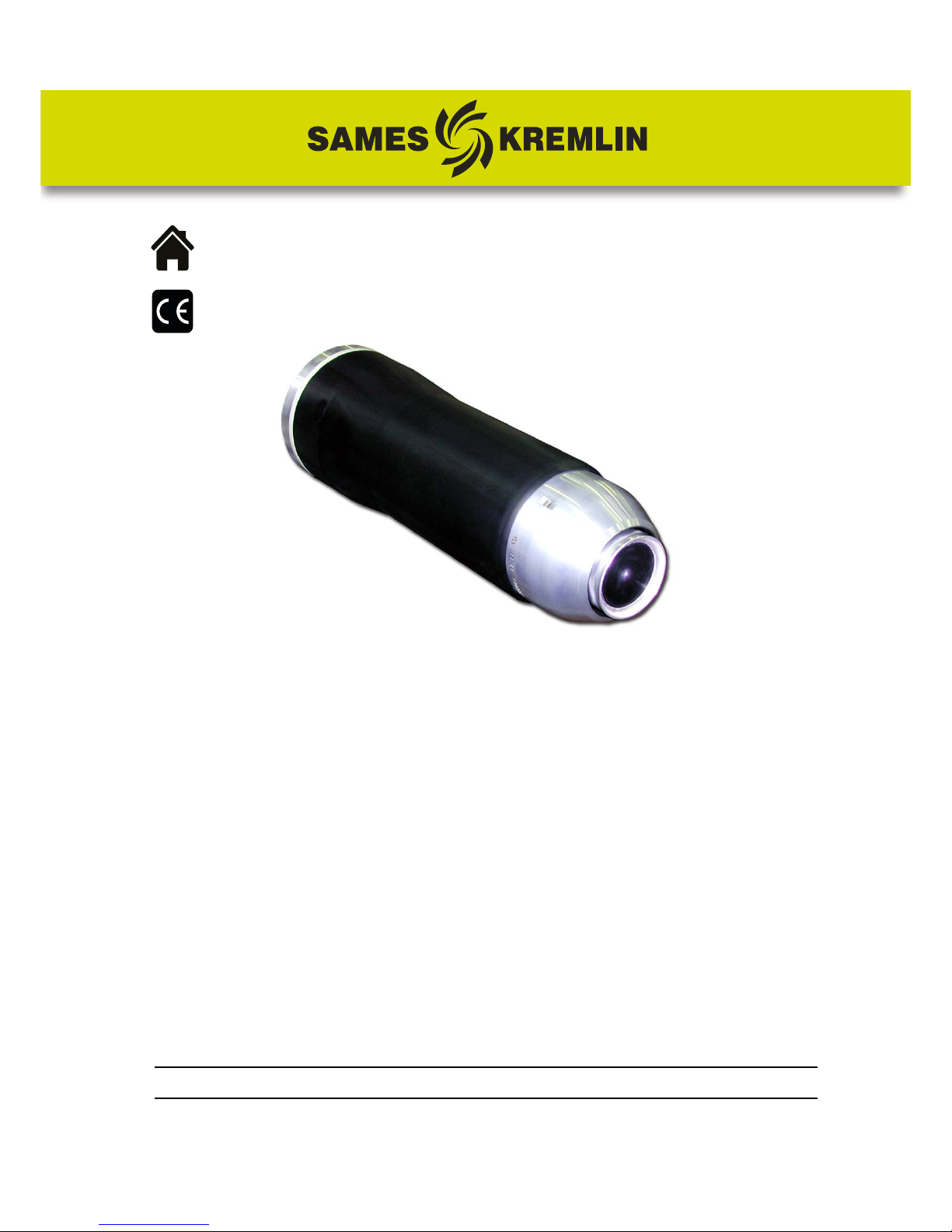
PPH 308
with high voltage cable
for solvent-based paints
Page 2

Index revision : C - November 2017 2 7030
All communication or reproduction of this document, in any form whatsoever and all use or
communication of its contents are forbidden without express written authorisation from
SAMES
KREMLIN.
The descriptions and characteristics mentioned in this document are subject to change without
prior notice.
© SAMES KREMLIN 2006
WARNING : SAMES KREMLIN SAS is registered with the Ministry of Labour as a training
institution.
Throughout the year, our company offers training courses in the operation and
maintenance of your equipment.
A catalogue is available on request. Choose from a wide range of courses to
acquire the skills or knowledge that is required to match your production
requirements and objectives.
Our training courses can be delivered at your site or in the training centre at our
Meylan head office.
Training department:
Tel. 33 (0)4 76 41 60 04
E-mail: [email protected]
SAMES KREMLIN SAS operating manuals are written in French and translated into English, German, Spanish, Italian
and Portuguese.
The French version is deemed the official text and SAMES KREMLIN will not be liable for the translations into other
languages.
Page 3

Index revision : 3
PPH 308
with high voltage cable
for solvent-based paints
1. Health and Safety Instructions- - - - - - - - - - - - - - - - - - - - - - - - - - - - 6
1.1. Configuration of certified equipment . . . . . . . . . . . . . . . . . 6
1.2. Markings on atomizer . . . . . . . . . . . . . . . . . . . . . . . . . . . . . . . 6
1.3. Precautions foruse . . . . . . . . . . . . . . . . . . . . . . . . . . . . . . . . . 7
1.4. Warnings . . . . . . . . . . . . . . . . . . . . . . . . . . . . . . . . . . . . . . . . . . 7
1.4.1. Installation rules . . . . . . . . . . . . . . . . . . . . . . . . . . . . . . . . . . . . . 10
1.5. Important Recommendations . . . . . . . . . . . . . . . . . . . . . . . 12
1.5.1. Compressed air quality. . . . . . . . . . . . . . . . . . . . . . . . . . . . . . . 12
1.5.2. Product quality . . . . . . . . . . . . . . . . . . . . . . . . . . . . . . . . . . . . . 12
1.5.3. Bearing safety . . . . . . . . . . . . . . . . . . . . . . . . . . . . . . . . . . . . . . 12
1.5.4. Locking . . . . . . . . . . . . . . . . . . . . . . . . . . . . . . . . . . . . . . . . . . . . 13
1.5.5. Shaping air . . . . . . . . . . . . . . . . . . . . . . . . . . . . . . . . . . . . . . . . . 13
1.5.6. High voltage . . . . . . . . . . . . . . . . . . . . . . . . . . . . . . . . . . . . . . . 13
1.5.7. Maximum speed . . . . . . . . . . . . . . . . . . . . . . . . . . . . . . . . . . . . 13
1.5.8. Bell Cup / Turbine Fitting. . . . . . . . . . . . . . . . . . . . . . . . . . . . . . 13
1.5.9. O-ring seals. . . . . . . . . . . . . . . . . . . . . . . . . . . . . . . . . . . . . . . . . 13
1.5.10. Ventilation . . . . . . . . . . . . . . . . . . . . . . . . . . . . . . . . . . . . . . . . 14
1.5.11. Vibrations . . . . . . . . . . . . . . . . . . . . . . . . . . . . . . . . . . . . . . . . . 14
1.5.12. Residual pressure. . . . . . . . . . . . . . . . . . . . . . . . . . . . . . . . . . . 14
1.5.13. Safety devices . . . . . . . . . . . . . . . . . . . . . . . . . . . . . . . . . . . . . 14
1.5.14. Mechanical collision. . . . . . . . . . . . . . . . . . . . . . . . . . . . . . . . 14
1.5.15. Ambient temperature. . . . . . . . . . . . . . . . . . . . . . . . . . . . . . . 14
1.5.16. Noise level . . . . . . . . . . . . . . . . . . . . . . . . . . . . . . . . . . . . . . . . 15
1.5.17. Special maintenance provisions . . . . . . . . . . . . . . . . . . . . . 15
1.6. Warranty . . . . . . . . . . . . . . . . . . . . . . . . . . . . . . . . . . . . . . . . . 16
2. Description - - - - - - - - - - - - - - - - - - - - - - - - - - - - - - - - - - - - - - - - - 17
2.1. Dual-channel air/solvent microvalve unit (1 PV block) . . 18
2.2. MANIFOLD block . . . . . . . . . . . . . . . . . . . . . . . . . . . . . . . . . . 18
2.3. Injector, injector holder and restrictor . . . . . . . . . . . . . . . . 18
2.4. “Magnetic bell cup” type magnetic air bearing turbine 19
2.5. Shaping air . . . . . . . . . . . . . . . . . . . . . . . . . . . . . . . . . . . . . . 19
2.6. Outer cover . . . . . . . . . . . . . . . . . . . . . . . . . . . . . . . . . . . . . 19
2.6.1. Rinsing the outside of the bell cup. . . . . . . . . . . . . . . . . . . . . 19
2.7. Bell cups . . . . . . . . . . . . . . . . . . . . . . . . . . . . . . . . . . . . . . . . 19
3. Technical characteristics - - - - - - - - - - - - - - - - - - - - - - - - - - - - - - 20
3.1. Dimensions (mm) . . . . . . . . . . . . . . . . . . . . . . . . . . . . . . . . . . 20
3.2. Operating characteristics . . . . . . . . . . . . . . . . . . . . . . . . . . 21
3.3. Operating principle . . . . . . . . . . . . . . . . . . . . . . . . . . . . . . . 22
3.3.1. Turbine . . . . . . . . . . . . . . . . . . . . . . . . . . . . . . . . . . . . . . . . . . . . 22
3.3.2. Turbine Rotation Speed. . . . . . . . . . . . . . . . . . . . . . . . . . . . . . 23
3.3.3. Microphone . . . . . . . . . . . . . . . . . . . . . . . . . . . . . . . . . . . . . . . . 23
Page 4

Index revision : 4
4. Fluid Diagram of the Various Circuits - - - - - - - - - - - - - - - - - - - - - 24
4.1. Paint flow diagram . . . . . . . . . . . . . . . . . . . . . . . . . . . . . . . . 24
4.2. Bell cup and injector rinsing diagram . . . . . . . . . . . . . . . . . 24
4.3. Microphone air diagram . . . . . . . . . . . . . . . . . . . . . . . . . . . 25
4.4. Turbine rotation diagram . . . . . . . . . . . . . . . . . . . . . . . . . . 25
4.5. Shaping air diagram . . . . . . . . . . . . . . . . . . . . . . . . . . . . . . . 25
4.6. Compensation air diagram . . . . . . . . . . . . . . . . . . . . . . . . . 26
4.7. Turbine exhaust diagram . . . . . . . . . . . . . . . . . . . . . . . . . . . 26
4.8. Colour change and rinsing cycles . . . . . . . . . . . . . . . . . . . 27
5. Maintenance - - - - - - - - - - - - - - - - - - - - - - - - - - - - - - - - - - - - - - - 29
5.1. Shut-down and start-up procedures . . . . . . . . . . . . . . . . . 29
5.1.1. Shut-down Procedure . . . . . . . . . . . . . . . . . . . . . . . . . . . . . . . 29
5.1.2. Start-up Procedure. . . . . . . . . . . . . . . . . . . . . . . . . . . . . . . . . . 29
5.2. Tools . . . . . . . . . . . . . . . . . . . . . . . . . . . . . . . . . . . . . . . . . . . . 30
5.3. Installing the Atomizer . . . . . . . . . . . . . . . . . . . . . . . . . . . . . 32
6. Atomizer Maintenance- - - - - - - - - - - - - - - - - - - - - - - - - - - - - - - - 33
6.1. Removing and re-installing the PPH 308 . . . . . . . . . . . . . . . 33
6.1.1. Disassembly . . . . . . . . . . . . . . . . . . . . . . . . . . . . . . . . . . . . . . . . 33
6.1.2. Reassembly . . . . . . . . . . . . . . . . . . . . . . . . . . . . . . . . . . . . . . . . 33
6.2. Bell cups . . . . . . . . . . . . . . . . . . . . . . . . . . . . . . . . . . . . . . . . 33
6.3. Shaping air assembly (shroud and cover) . . . . . . . . . . . . . 33
6.4. Turbine . . . . . . . . . . . . . . . . . . . . . . . . . . . . . . . . . . . . . . . . . . 33
6.5. Injector holder . . . . . . . . . . . . . . . . . . . . . . . . . . . . . . . . . . . 34
6.6. Injector . . . . . . . . . . . . . . . . . . . . . . . . . . . . . . . . . . . . . . . . . . 34
6.6.1. Disassembly . . . . . . . . . . . . . . . . . . . . . . . . . . . . . . . . . . . . . . . . 34
6.6.2. Reassembly . . . . . . . . . . . . . . . . . . . . . . . . . . . . . . . . . . . . . . . . 34
6.7. 1 PV Block and Manifold Block . . . . . . . . . . . . . . . . . . . . . . 35
6.7.1. Disassembly . . . . . . . . . . . . . . . . . . . . . . . . . . . . . . . . . . . . . . . . 35
6.7.2. Reassembly . . . . . . . . . . . . . . . . . . . . . . . . . . . . . . . . . . . . . . . . 35
6.8. Microvalves . . . . . . . . . . . . . . . . . . . . . . . . . . . . . . . . . . . . . . 35
6.9. High Voltage Connection . . . . . . . . . . . . . . . . . . . . . . . . . . 36
6.9.1. Preparing the high voltage connection. . . . . . . . . . . . . . . . . 36
6.9.2. Assembling / disassembling the internal resistor in the
placebo . . . . . . . . . . . . . . . . . . . . . . . . . . . . . . . . . . . . . . . . . . . . . . . . 37
6.9.3. Installation on atomizer. . . . . . . . . . . . . . . . . . . . . . . . . . . . . . . 38
7. Cleaning Procedures - - - - - - - - - - - - - - - - - - - - - - - - - - - - - - - - - 39
7.1. Procedure A . . . . . . . . . . . . . . . . . . . . . . . . . . . . . . . . . . . . . 40
7.2. Procedure B . . . . . . . . . . . . . . . . . . . . . . . . . . . . . . . . . . . . . . 41
7.2.1. Bell cup . . . . . . . . . . . . . . . . . . . . . . . . . . . . . . . . . . . . . . . . . . . 41
7.2.2. Outer cover. . . . . . . . . . . . . . . . . . . . . . . . . . . . . . . . . . . . . . . . 42
7.2.3. Injector and Injector Holder. . . . . . . . . . . . . . . . . . . . . . . . . . . 42
8. Spare Parts List - - - - - - - - - - - - - - - - - - - - - - - - - - - - - - - - - - - - - - 43
8.1. Single-circuit PPH 308 for solvent-based paints of
resistivity 0.5 < ρ ≤ 6 MΩ.cm . . . . . . . . . . . . . . . . . . . . . . . . . . . . . 43
8.2. 1 PV Block . . . . . . . . . . . . . . . . . . . . . . . . . . . . . . . . . . . . . . . . 45
Page 5

Index revision : 5
8.3. MANIFOLD Block . . . . . . . . . . . . . . . . . . . . . . . . . . . . . . . . . . 46
8.4. Injector / Injector holder assembly . . . . . . . . . . . . . . . . . . . 48
8.5. Placebo and resistor . . . . . . . . . . . . . . . . . . . . . . . . . . . . . . . 49
8.5.1. To connect to one PPH 308 atomizer . . . . . . . . . . . . . . . . . . . 49
8.5.2. To connect two PPH 308 atomizers to a single HVU
(optional) . . . . . . . . . . . . . . . . . . . . . . . . . . . . . . . . . . . . . . . . . . . . . . . 50
8.6. Grounding kit . . . . . . . . . . . . . . . . . . . . . . . . . . . . . . . . . . . . . 51
8.7. Turbine, injector and restrictor seals . . . . . . . . . . . . . . . . . . 52
Page 6
Index revision : C - November 2017 6 7030
1. Health and Safety Instructions
This manual contains links to the user manuals for the following:
• see RT Nr 6285 for magnetic bell cups,
• see RT Nr 6350 for the “Magnetic bell cup” type magnetic air turbine.
• see RT Nr 6021 for the microvalve
• see RT Nr 6190 for the microphone,
• see RT Nr 7010 high-voltage unit UHT 188 EEx e.
• see RT Nr 6213 GNM200 control module user manual,
• see RT Nr 6364 for the electrical systems user manual,
1.1. Configuration of certified equipment
These user manuals define the configuration of certified equipment.
1.2. Markings on atomizer
SAMES KREMLIN Meylan France
CE 0080
PPH
P/N: *
ISSeP06ATEX032X**
II 2 G
EEx > 350mJ
(Serial no.)
* ATEX PPH 308 configurations
** 'X' indicates that the safety distance specified in this manual (between the HV components
of the atomizer and all grounded parts) must be observed to ensure safe operation of the
equipment.
Atomizer - P/N 910003350
Microvalves - P/N 1507375
Turbine - P/N 910000295
High-voltage unit UHT 188 EEx e -
P/N 910001759
P/N without HV cable
Note: refer to health and safety
instructions for maximum lengths
of electrical capacities
P/N PPH
(*)
GNM 200A
P/N 1517071
X X 910003721 X
Page 7
Index revision : C - November 2017 7 7030
1.3. Precautions foruse
This document contains information that every operator must be familiar with and understand
before using the PPH 308 atomizer. This information highlights situations that could result in seri
-
ous damage and indicates the precautions that should be taken to avoid them.
WARNING : Before any use of the PPH 308 equipment, check that all operators:
• have previously be trained by the compagny SAMES KREMLIN, or by its distributors
registered for this purpose.
• have read and understood the user manual and all rules for installation and operation, as
laid out below.
It is the responsibility of the operators’ workshop manager to ensure these two points and it is
also his responsibility to make sure that all operators have read and understood the user man
-
uals for any peripheral electrical equipment present in the spraying area.
1.4. Warnings
WARNING : This equipment may be dangerous if it is not used, disassembled and reassembled
in compliance with the regulations specified in this manual and in all applicable
European standards or national safety regulations.
WARNING : Equipment performance is only guaranteed if original spare parts distributed by
SAMES KREMLIN are used.
Page 8

Index revision : C - November 2017 8 7030
WARNING :
This device must only be used in spraying areas that comply with European standards EN 50176,
EN 50177, EN 50223 or equivalent ventilation conditions. Equipment must be used only in wellventilated areas, in order to reduce health, fire and explosi on hazards. The efficiency of the
ventilation system must be verified on a daily basis.
In potentially explosive atmospheres generated by the spraying process, only the appropriate
electrical equipment, protected against explosions, should be used.
Before cleaning or working on atomizers in the spraying area, the high voltage generator must
be switched off and the HV circuit (atomizer) discharged to the ground.
.
Never point the pressurized product or the compressed air towards persons or animals.
Suitable measures must be taken to ensure there is no potential energy (liquid, air pressure or
electricity) in the equipment during downtimes and/or periods when the equipment is not
being used.
The use of personal protective equipment can limit the risks caused by con tact with and/or
inhalation of toxic products, gases, vapours, mist and dust likely to be generated by the
equipment in use. The operator must follow the manufacturer's instructions for the coating
product.
The electrostatic spraying device must be regularly serviced in accordance with the indications
and instructions given by SAMES KREMLIN.
The equipment must be cleaned either in authorized areas equipped with a mechanical
ventilation system, or using cleaning fluids with a flash point at least 5°C higher than the ambient
temperature.
Cleaning fluids must be held in metal containers that are securely grounded.
No naked flames, incandescent objects, devices or items likely to produce sparks inside the
paint booth.
No storage of inflammable products or their containers close to the booth or near the doors.
The surrounding area must be kept clear and clean.
Page 9
Index revision : C - November 2017 9 7030
WARNING : The use of extra high voltage power increases the risk of sparks. SAMES KREMLIN
atomizers and high-voltage electrostatic generators are designed to minimise this risk.
Although the HV electrode is the only accessible part, a safety distance of X mm (see table
below) must be maintained between the HV parts of the atomizer and all grounded parts.
PPH 308 with high voltage unit (HVU) 188 and 9m-long HV cable:
Authorised spraying distance
The authorised operating distances specified in this manual are calculated on the basis of the
total length of high voltage cables (electrical capacities). The atomizer must be connected to
the HV socket on the HVU only with a single length of HV cable, with on intermediate part.
In addition, a careful check must be made to ensure that any conducting or semi-conducting
part closer than 2.5 m to the atomizer is properly grounded.
If not, electrical charges capable of causing sparks could build up on it. The same appl ies to
operating staff, which is why antistatic shoes and gloves should be worn to protect against this
hazard.
Each substrate must have a ground resistance of less than or equal to 1 MΩ (measurement
voltage at least 500V). This resistance value must be regularly checked.
All conductive casing or lining of electrical equipment and conductive components in
potentially explosive atmospheres must be grounded by connecting them to the grounding
terminal.
Finally, and for the same reasons, the floor in the area in which the operator works must be antistatic (bare concrete, metal duckboard, etc.).
It is essential to provide sufficient ventilation in the spraying booths to avoid the build up of
inflammable vapours.
The correct operation of the overcurrent protection (di/dt) must be verified daily. This check
must be carried out in an area with no explosive atmosphere, by placing a ground wire near
the electrode, with the atomizer switched on (the operator must by grounded): the control
module must switch to the fault state.
The associated apparatus must be located outside hazardous areas, and its operation must be
interlocked with that of the booth e xtraction fan. The correct operation of the servocontrol
Voltage
(kV)
Distance
(mm)
0
7550
60
70
135
80
90
150
100
0
20
40
60
80
100
120
140
160
0 5060708090100
Distance (mm)
Voltage (kV)
Safety distance 'X' as a function of voltage
Non-authorised spraying area
Page 10

Index revision : C - November 2017 10 7030
system must be verified once a week.
A warning sign must be placed in full view near the spraying area.
Excessive turbine speed can result in serious damage to the turbine and loss of connection
between the bell cup and turbine, presenting a risk to persons and equipment. Do not exceed
the maximum operating speed (
see § 3 page 20).
1.4.1. Installation rules
• To use an UHT 188, it must be connected to a GNM 200 whose firmware is v ersion V 5.63 or
later.
• If UHT 188 is used to supply a single atomizer, the HV cable must be no longer than 9m.
• If UHT 188 is used to supply two atomizers, the sum of the HV cable lengths must be no
more than 8.5m.
e.g. If both atomizers are at the same distance from HVU 188, the allowable length of
each HV cable is no more than 4.25 m (8.5/2 = 4.25 m).
If two atomizers are used, please note that as a part to be painted is brought close to one
atomizer, the voltage to the second atomizer will simultaneously drop.
WARNING : The installation of any system that does not comply with the rules specified above
and below is strictly prohibited.
Page 11
Index revision : C - November 2017 11 7030
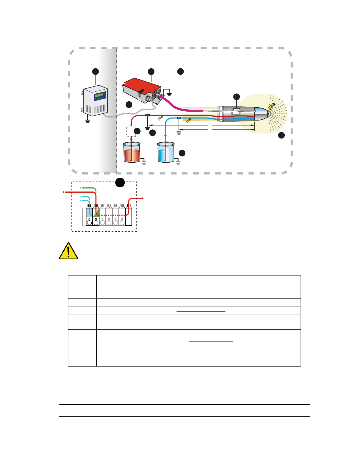
PPH 308 for low resistivity solvent-based paints ρ > 0.5 MΩ.cm
WARNING :
All conductive parts must be grounded (metal Moduclean connectors, gear pumps,
etc.)
Paint resistivity > 0.5 MΩ.cm
1 GNM 200 control module (to be installed in a non-ATEX zone)
2 Low voltage cable
3 High Voltage Unit HVU 188 EEx e
4 High voltage cable (Length: see § 1.4.1 page 10)
5 Paint and rinsing product feed lines, grounded
6 Dump circuit return outlet, grounded
7
Paint/rinsing product and dump connectors, grounded inside the atomizer by means of a grounding kit (see § 8.6 page 51)
8 Placebo with damping resistor
9
Safety distance (area around atomizer head - distance from high voltage
components such as outer cover, bell cup etc.)
S
1
2
5
DES03662
GNM
1
2
3 4
7
6
8
9m maxi.
9
5
DES03690
S: rinsing product
A: air intake
1: product intake 1
2: product intake 2
ρ > 0.5 MΩ.cm : L = 5 m
Int.Dia.: 5 mm
Note: L Distance at which
grounding of paint, solvent and
dump circuits requires a special kit
(see § 8.6 page 51)
Page 12
Index revision : C - November 2017 12 7030
1.5. Important Recommendations
1.5.1. Compressed air quality
The air must be properly filtered to promote long service life and to prevent contamination
during painting.
The filter must be installed as close to the installation as possible. Filter cartridges must be
changed regularly to ensure that the air is clean.
PTFE tape or glue should not be used between the filter and the bearing, since glue residue or
pieces of PTFE may block the small holes in the air bearing and cause turbine failure.
The inside of all pneumatic hoses supplying air to the atomizer and the holes on the body must
be clean and free of any traces of paint, solvent or other foreign matter.
The warranty does not cover faults caused by unclean, unfiltered bearing area, where the
above specifications have not be observed.
WARNING :
If the air is not correctly filtered, the bearing may become fouled, resulting in a
turbine operating fault. A filtering system must be set up, in particular to prevent
particles larger than 5 µm diameter reaching the bearing.
WARNING : The warranty does not cover damage caused by foreign matter (paint,
solvent or other foreign matter) entering the air circuits of atomizer PPH 308.
1.5.2. Product quality
The paint must be filtered to prevent any damage to the atomizer.
The maximum permissible particle size in the atomizer is 200 µm.
1.5.3. Bearing safety
The compressed air connection to the magnetic air bearing must be directly coupled to the
feed circuit (no intermediate isolating valve).
The air bearing must be permanently pressurised in operation, otherwise significant damage
may be caused. A sudden shutdown of the air supply could destroy the magnetic bearing of
the turbine. Wait until the turbine has completely shut down be fore stopping the bearing air
supply.
Procedure for shutting off air to the air bearing:
• Switch off the turbine rotation air supply
• Wait until the turbine has completely shut down (at least 150 sec.).
• Shut off the bearing air supply.
Damage may be caused to the bearing if the turbine is operate at bearing air pressure of less
than 6 bar at the atomizer inlet. The standard bearing air pressure is 6 bar at the air cont rol
cabinet.
All these pressure values are measured at the atomizer inlet. If bearing air pressure goes below
6 bar at the turbine or atomizer inlet, shut off air supply to the turbine.
In addition, a 25 l air reserve should be available to ensure that the turbine brakes gradually if
the main air supply is suddenly cut off.
WARNING : The warranty does not cover faults caused by turbine operation when there is
insufficient bearing air pressure.
Page 13
Index revision : C - November 2017 13 7030
1.5.4. Locking
Do not spray if the bell cup is rotating at less than 15,000 rpm. At lower speeds, paint or solvent
may enter the turbine, bearing and control circuits. Opening the head valve, injector rinsing
valve and bell cup exterior rinsing valve is therefore prohibited when the bell cup is not rotating.
Only qualified personnel are authorised to by-pass this locking system for flow rate checks.
WARNING : When the turbine is initially shut down, wait until the bell cup is rotating (min. 15,000
rpm) before opening the head valve. The recommended minimum waiting time is
2 seconds.
1.5.5. Shaping air
Do not spray if there is not a minim um of 8 0 N l/min sh aping ai r ( i.e . 0.3 b a r at atomizer inlet) At
lower pressures, the product may re-enter the device and foul the outer cover and the inner
surfaces of the shaping air shroud, resulting in incorrect application.
1.5.6. High voltage
High voltage operation should be prohibited when atomizer PPH 308 is not spraying for an
extended period (conveyor shutdown, objects not painted, holes etc.), to prevent air
ionisation.
WARNING : High voltage power supply must be disconnected before performing rinsing cycles
(bell cup exterior and injector).
1.5.7. Maximum speed
Excessive turbine speeds cause considerable damage to the turbine. The speed must not
exceed 45,000 rpm.
WARNING : The warranty does not cover damage resulting from rotation speeds greater than
45,000 rpm.
1.5.8. Bell Cup / Turbine Fitting
The bell cup must be properly fitted to the turbine. A “click” should be heard when it is
assembled. The two cylinder should rest one against the other, without any foreign body
between them. If they are incorrectly assembled, they may come apart and the bell cup
ejected while revolving, causing a hazard for people and equipment.
1.5.9. O-ring seals
Use the seals recommended in this manual. If solvent-based products are used, seals coming
into contact with the product should be chemically-inert O-rings in order to prevent swelling or
chemical corrosion. Correct operation of the PPH 308 is only guaranteed if it is used wi th seals
whose dimensions and materials comply with those specified in the manual.
Page 14

Index revision : C - November 2017 14 7030
1.5.10. Ventilation
Do not start painting with the PPH 308 until the spraying booth ventilation system is operating. If
the ventilation is cut, toxic substances such as organic solvents or ozone may remain in the
spraying booth, resulting in a risk of fire, poisoning or irritation.
1.5.11. Vibrations
If the atomizer vibrates more than usual, the cause is generally unbalanced rotating parts.
There may be dry paint deposits on the bell cup or rotor. If any of these situations arise, it is
essential to correct them. Excessive unbalance may damage the turbin e resulting i n failure to
operate or even loss of the bell cup / turbine connection, presenting a risk for persons and
equipment.
WARNING : The warranty does not cover damage caused by imbalance of rotating parts.
1.5.12. Residual pressure
Before all maintenance or repair operations, remove paint and solvent from the atomizer,
switch off the high voltage power supply and cut the paint, solvent and air supplies, then
release residual pressure in each supply system. Residual pressure may lead to component
damage and expose personnel to serious injuries. Paint or solvent dispersion may also lead to
poisoning or irritation.
1.5.13. Safety devices
During installation of the PPH 308, it is important to set up safety devices enabling high voltage
power, paint, solvent and air supplies to be cut immediately if there is a problem.
• Detection of control system faults.
• Detection of high voltage surges associated with the SAMES HV generator.
• Detection of air pressure drops.
• Detection of ventilation failure.
• Detection of fire.
• Detection of human presence.
• Detection of turbine rotation speed faults.
Failure to use such safety systems could cause a fire hazard, put operating staff at risk of serious
injury and damage the equipment.
1.5.14. Mechanical collision
The warranty does not cover damage resulting from the operating environment (e.g.: collision
with robot).
1.5.15. Ambient temperature
The atomizer is designed for normal operation at an ambient temperature of between 0°C and
+ 40°C.
To optimise the quality of application, recommended operating temperatures are between +
15°C and + 28°C.
The storage temperature must never exceed +60°C.
Page 15

Index revision : C - November 2017 15 7030
1.5.16. Noise level
The weighted equivalent continuous sound pressure level is 59.7 dB(A).
Measurement conditions:
The apparatus was operated to maximum capacity and the measurements taken in the paint
test booth (sealed booth with glass panels) i n the SAMES KREMLIN R&D laboratory in Meylan,
France.
Measurement method:
The weighted equivalent sound pressure level of 59.7 db(A) is an Leq (equivalent sound
pressure) value measured over observation periods of at least 30 seconds.
1.5.17. Special maintenance provisions
All access to the booth near the atomizer must be controlled during atomizer operation by
active devices (
see § 1.5.13 page 14) designed to interrupt operation in case of personne l
intrusion.
However, for maintenance purposes, these devices can be adapted to allow certain
operations and inspections (by personnel trained by SAMES KREMLIN).
Nevertheless, turbine rotation with a bell cup must always be prohibited with people in the
vicinity.
Page 16

Index revision : C - November 2017 16 7030
1.6. Warranty
Under the warranty, which applies only to the b uyer, SAMES KREMLIN under takes to re pair
operating faults resulting from a design fault, materials or manufacture, under the conditions
set out below.
The warranty claim must define the exact nature of the fault concerned, in writing. The
SAMES KREMLIN warranty only covers equipment that has been serviced and cleaned
according to standard procedures and our own instructions, that has been fitted with parts
approved by SAMES or that has not been modified by the customer.
More specifically, the warranty does not cover damage resulting from:
• the customer's negligence or inattention,
• incorrect use,
• failure to follow procedures,
• use of a control system not designed by SAMES KREMLIN or a SAMES KREMLIN
control system modified by a third party without written permission from an authorised
SAMES KREMLIN technical agent,
• accidents such as a collision with external objects, or similar events,
• flooding, earthquake, fire or similar events,
• inadequately filtered bearing air (solid particles more than 5 mm in diameter),
• inadequately filtered paint and solvent,
• use of seals not complying with SAMES KREMLIN recommendations,
• turbine operation without minimum bearing air pressure (6 bar),
• exceeding the maximum speed of 45,000 rpm under load,
• operation of rotating parts that are unbalanced (dry paint on bell cup, damaged rotor
attachment cone or bell cup(s)),
• contamination of air circuits by fluids or substances other than air.
The SAMES KREMLIN PPH 308 atomizer is covered by a one-year warranty for use in two 8hour shifts per day under normal operating conditions.
By concession, the warranty is extended to 10,000 hours on the air turbine of the PPH308. The
warranty does not apply to wearing parts such as spraying bell cups, membranes, seals etc.
The warranty start date shall be deemed to be the date of first operation or of the provisional
acceptance report.
Under no circumstances, either in the context of this warranty or in other contexts, shall
SAMES KREMLIN be liable for physical injury, property damage or related losses, damage to
brand image and loss of production resulting directly from its products.
Page 17
Index revision : C - November 2017 17 7030
2. Description
The PPH 308 atomizer is used in automatic mode for the electrostatic spraying solvent liquid
paints.
The PPH 308 is a complete atomizer with built-in painting and rinsing assemblies. It is fitted with
an air-cushioned magnetic air bearing turbine capable of reaching a rotation speed of 45,000
rpm.
A careful study should be made of its design and tools, for quick and easy maintenance.
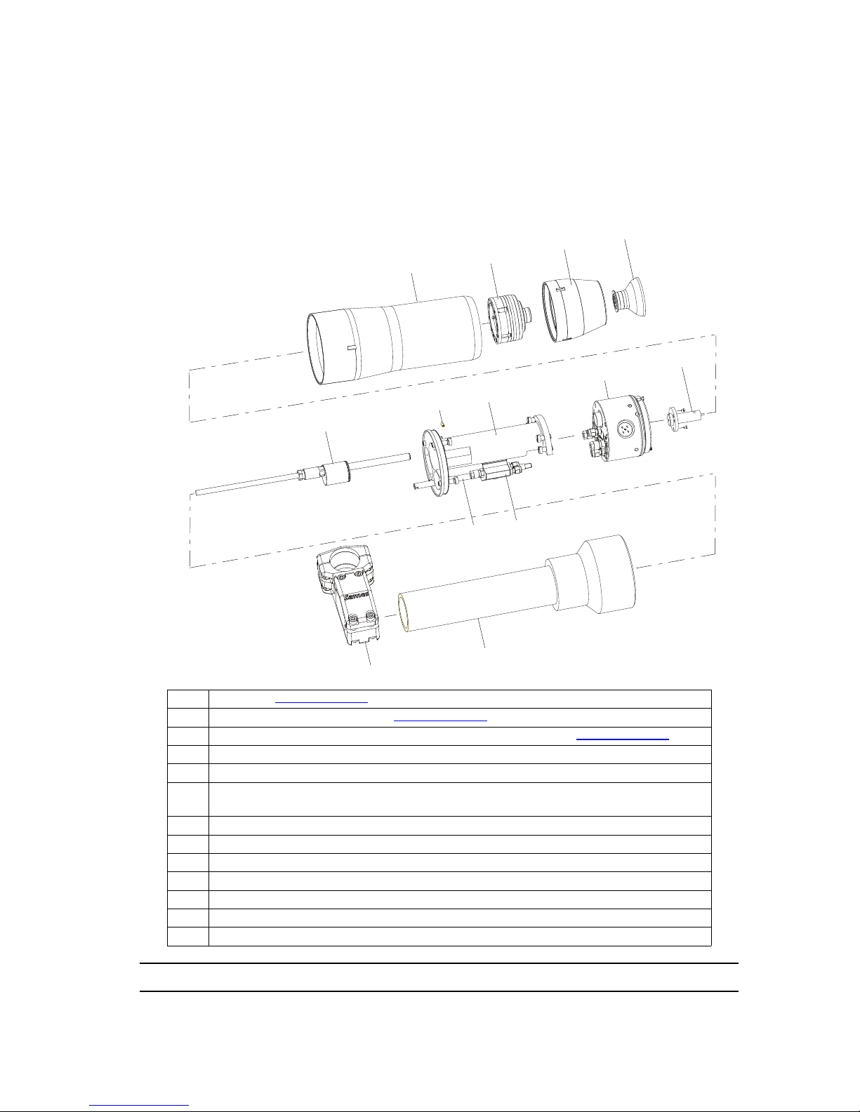
1 Bell cup (see RT Nr 6285)
2 Vortex air shroud assembly (see RT Nr 6285)
3 “Magnetic bell cup” type magnetic air bearing turbine (see RT Nr 6350)
4 Protective cover
5 Injector/ Injector holder
6 MANIFOLD block comprising three dual-channel product and dump microv-
alves
7 Placebo holder
8 Placebo locking screw
9 Placebo
10 Tie rod for the 1 PV block
11 Dual-channel air/solvent microvalve unit (1 PV block)
12 PPH support tube
13 Securing nut
DES03679
1
3
4
5
6
7
8
9
2
10
12
13
11
Page 18
Index revision : C - November 2017 18 7030
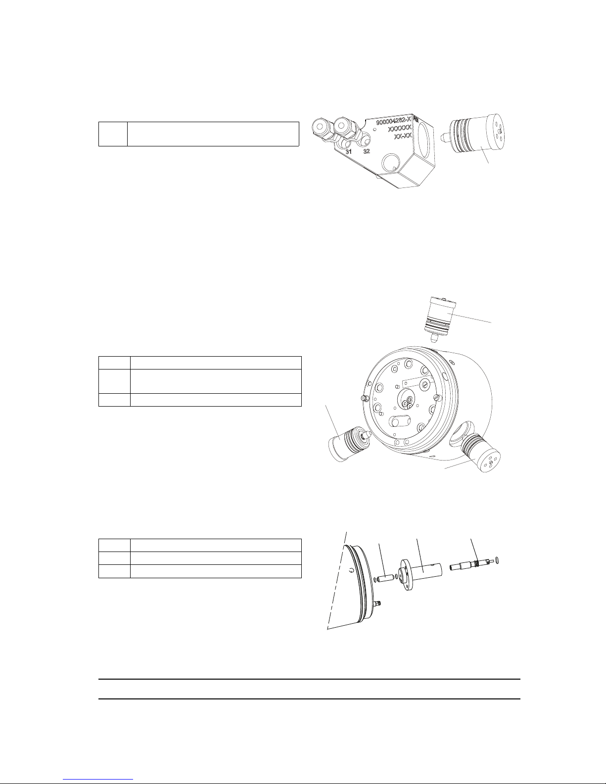
2.1. Dual-channel air/solvent microvalve unit (1 PV block)
This unit includes one air/solvent microvalve:
The dual-channel micovalves are aircontrolled and are normally in closed
position. They are involved in various
operations, such as external bell cup rinsing,
injector and paint supply rinsing, and paint
rinsing (these latter three are located in the
manifold block).
2.2. MANIFOLD block
This assembly includes three microvalves:
2.3. Injector, injector holder and restrictor
The restrictor provides a suitable pressure drop
for the required flow rate.
The injector holder is permanently secured to the
body of the PPH
308. It is fitted with an injector
whose restrictor can be changed according to the pressure drop required for the paint
spraying equipment and product used.
1
Air/solvent microvalve (PV 31) for
external bell cup rinsing
1 Dump microvalve (PV 41)
2
Air/solvent microvalve (PV 32) for
injector rinsing
3 Product microvalve (PV 11)
1 Restrictor (1.2 mm diameter)
2 Injector holder
3 Injector (1.8 mm diameter)
DES04177
1
2
1
3
DES01307
1
3
2
Page 19
Index revision : C - November 2017 19 7030
2.4. “Magnetic bell cup” type magnetic air bearing turbine
see RT Nr 6350
The bell cup is rotated by means of a pneumatic motor. Paint is sprayed due to the centrifugal
forces generated by rotation of the bell cup. Th e higher the rotational speed, the smaller the
particles that are sprayed.
2.5. Shaping air
The air supply circuit can be used to alter the spraying pattern. If the shaping air pressure is
increased, the pattern is narrower and likewise, if it is decreased the pattern is wider.
The shaping air arrives on the turbine side, flows through the holes on outside of the shaping air
assembly and is then directed towards the bell cup.
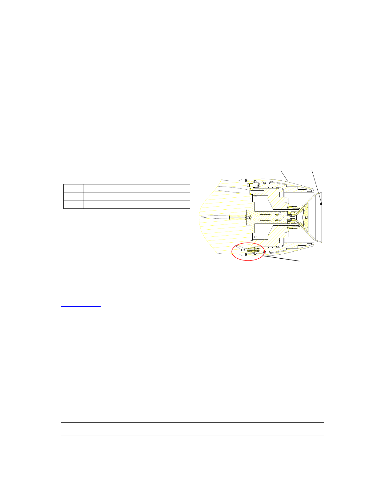
2.6. Outer cover
The outer air shroud acts as a cover, and also facilitates cleaning of the atomizer.
2.6.1. Rinsing the outside of the bell cup
The solvent flows through a nozzle and uses one
of the openings in the air shroud to rinse the
outside of the bell cup.
2.7. Bell cups
see RT Nr 6285
The bell cup atomises all particle-base paint types . Select the appropriate bell cup according
to the type of product used.
1 Shaping air assembly
2 Bell cup
3 Solvent pipette
1
2
3
Page 20
Index revision : C - November 2017 20 7030
3. Technical characteristics
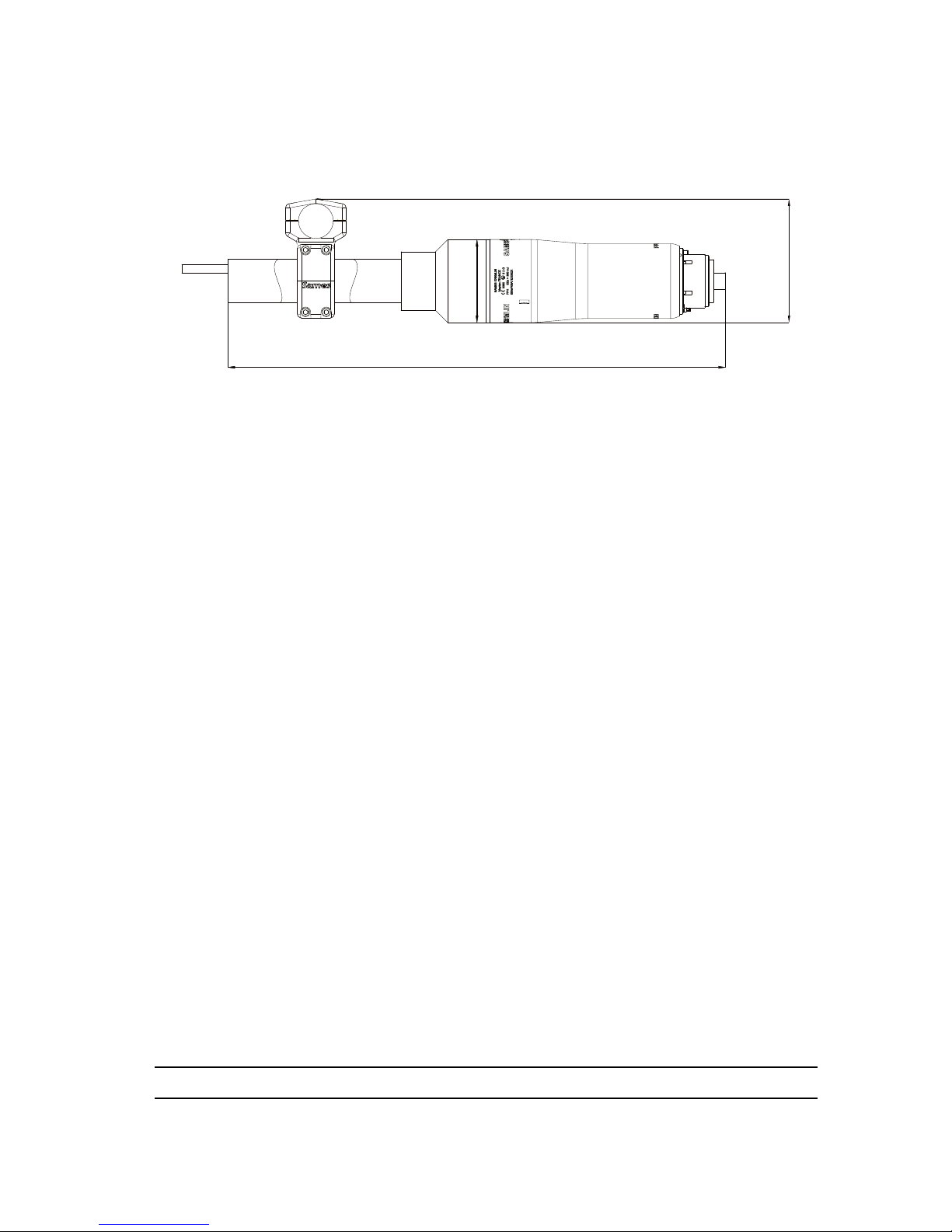
3.1. Dimensions (mm)
719
Dia: 120
179
Page 21

Index revision : C - November 2017 21 7030
3.2. Operating characteristics
* Resistivity values measured with Resistivohmeter AP 1000 (SAMES P/N: 910005790). For lower
values, contact SAMES KREMLIN.
For values greater than 6 MΩ.cm, you are advised to use the PPH 308 with integrated high
voltage unit.
** m
0
3
values given for a temperature of 20 °C at 1013 mbar atmospheric pressure.
Weight
PPH 308 without hoses or cables 2.5 kg
Current
Maximum operating voltage 100 kV
Maximum operating current 200 μA
Speed
Recommended rotation speed 10,000 to 45,000 rpm
Paint
Paint flow rate
30 to 500 cc/min max. (depending on
paint)
Normal supply pressure 6 to 8 bar
Maximum pressure 10 bar max.
Viscosity 12 to 40 seconds - FORD cup # 4
Viscosity 12 to 45 seconds - AFNOR cup # 4
Paint resistivity ρ ≥ 0,5 MΩ.cm *
Air pressure
Microvalve pilot 6 to 10 bar max.
Bearing air 6 to 7 bar max.
Microphone air 1.9 to 3 bar constant
Shaping air 6 bar maximum
Compressed Air quality
Filtered (bearing air), dry, oil and dust-free according to standard NF ISO 8573-1
Maximum dew point at 6 bar (87psi) Class 4, i.e + 3° C (37° F)
Maximum oil concentration
Class 4, i.e 2 mg / m
0
3 **
Maximum particle size of solid contaminants
Class 3, i.e 5 μm
Maximum concentration of solid contaminants
5 mg /m
0
3 **
Air consumption
Pilot 10 Nl/min
Bearing air 125 Nl/min
Shaping air
0 to 600 Nl/min according to the shap-
ing air assembly used
Turbine see RT Nr 6350
Page 22
Index revision : C - November 2017 22 7030
3.3. Operating principle
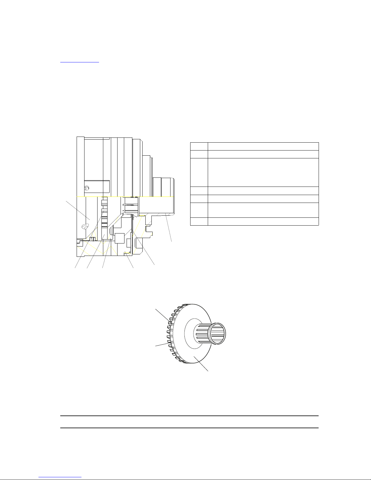
3.3.1. Turbine
see RT Nr 6350
This turbine has no mechanical shaft and is kept aligned simply by the polarity difference
between the bearing magnets. This system also completely eliminates friction.
The bearing air, which is uniformly distributed across the stator surface generates an air cushion,
separating rotor and stator. The rotor can turn freely, held in place by the balance of the
pressure and magnetic forces. The air directed onto the turbine blades makes it possible to
rotate or brake the rotor.
The product is sprayed due to the centrifugal forces genera ted by the bell cup ro tation. To a
certain extent, the size of the particles sprayed decreases as the rotation speed increases.
1 Rotor
2 Stator magnet
3
Turbine body (stator) with a supply of:
- Bearing air
- Turbine rotation and braking air
- Shaping air
4 Openings for turbine braking
5 Teeth for turbine rotation
6
Drive vane for braking and
rotation
7 Deflector fitted with seal
DES02669
1
2
3
4
56
7
1
5
6
Page 23
Index revision : C - November 2017 23 7030
3.3.2. Turbine Rotation Speed
Measurement of rotation speed is based on an acoustic principle.
Air enters via the injector holder. The machined groove in the “microphone reader” on the bell
cup allows rotational air through.
This pressure variation generates a noise, or “frequency signal”, which travels through the
injector holder and is picked up by a microphone.
The microphone converts the acoustic signal into an electrical frequency signal in order to be
processed by the turbine speed regulation module. One pulse is emitted for each revolution.
3.3.3. Microphone
see RT Nr 6190
The microphone is linked to a SAMES KREMLIN frequency/voltage control to convert the
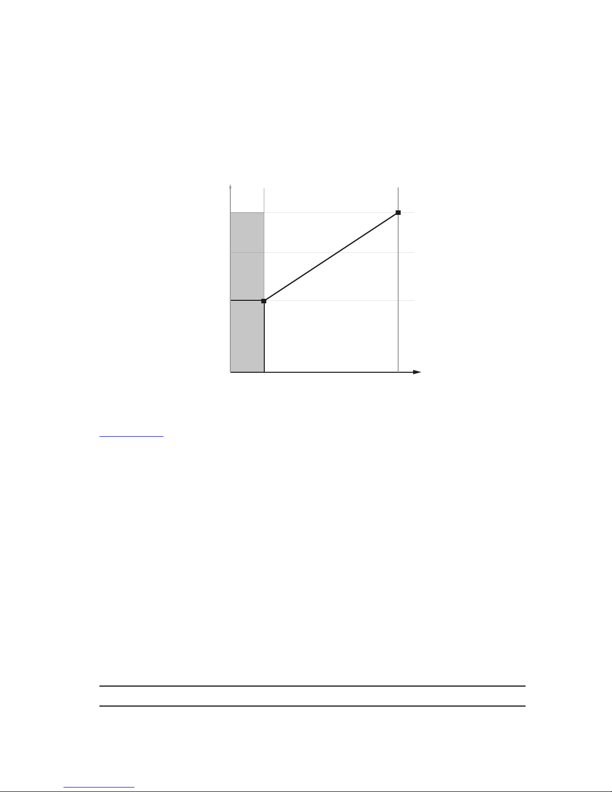
analogue frequency signal into an analogue level signal (0 - 10 V) or digital signal (pulse).
Please contact SAMES KREMLIN for the appropriate part number for use with your set-up.
DES01241
Outer dia.
1/4”
Maximum length
8 m
Required minimum length
4.5 m
Microphone input
Required pressure
1.9 - 3 bar
Page 24
Index revision : C - November 2017 24 7030
4. Fluid Diagram of the Various Circuits
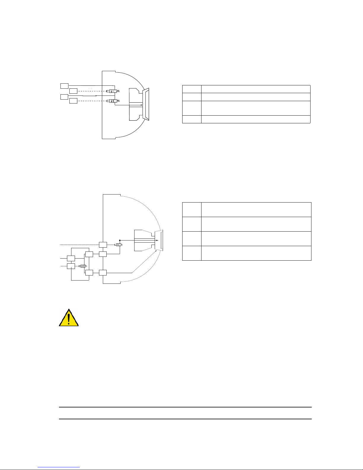
4.1. Paint flow diagram
For use of the rinsing circuit (generally used to change colours)
The “11” and ”41” hoses (5/8 PTFE) should be
sheathed with 9/12 PTFE hoses.
Note: PTFE hoses must never be replaced by polyamide hoses.
Blue hoses are used for the various different types of air supply.
Clear hoses are used for product.
4.2. Bell cup and injector rinsing diagram
31: Bell cup rinsing - the bell cup is rinsed via the
air/solvent inlet.
32: The air/solvent supply rinses the pa int supply
line up to the bell cup.
The “36” hose (4/6 PTFE) should be sheathed with 7/10 PTFE hose.
WARNING : The rinsing cycle must end with a compressed air sequence, circuits 31,32 and 36
must be purged and dried during 1 to 2 seconds before restarting the high voltage.
11 Paint supply - Dia. 5 x 8 PTFE
41 Dump - Dia 5 x 8 PTFE
51
Paint supply pilot -
Dia 2.7 x 4 - Polyamide
53 Dump pilot - Dia 2.7 x 4 - Polyamide
31
Solvent / air rinsing - Outside of bell
cup - Dia. 2 x 4 PTFE
32
Solvent / air rinsing - Injector - Dia. 2 x 4
PTFE
56
Solvent / air rinsing pilot - Injector - Dia.
2.7 x 4 - Polyamide
58
Solvent / air rinsing pilot - Outside of
bell cup - Dia. 2.7 x 4 - Polyamide
11
41
53
51
DES01309
PV32
PV31
36
58
31
32
56
32
31
Page 25
Index revision : C - November 2017 25 7030
4.3. Microphone air diagram
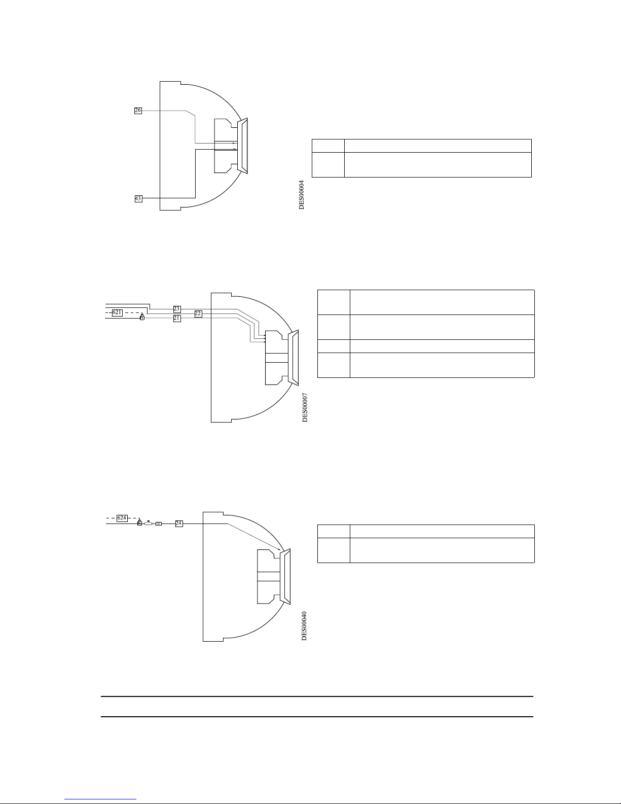
The microphone air is controlled by a remote
regulator.
4.4. Turbine rotation diagram
23: The bearing air separates the rotor from the
stator.
22: Supplies turbine braking air.
21: Supplies turbine rotation air.
The bell cup speed control module activates
circuit 21 via a proportional air valve and circuit
22 via a solenoid valve.
4.5. Shaping air diagram
24 : The shaping air supply controls the pattern
diameter.
Shaping air is controlled via a proportional air
valve.
26 Microphone air - Dia. 4 x 6 - Polyamide
43
Microphone return supply - Dia. 4 x 6 Polyamide
21 Turbine rotation - Dia. 7 x 10 - Polyure-
thane
22 Turbine braking - Dia. 6 x 8 - Polyam-
ide
23 Bearing air - Dia. 4 x 6 - Polyamide
621
Turbine rotation control/regulation -
Dia 2.7 x 4 - Polyamide
24 Shaping air - Dia. 6 x 8 - Polyamide
624
Shaping air control/regulation - Dia.
2.7 x 4 - Polyamide
Page 26
Index revision : C - November 2017 26 7030
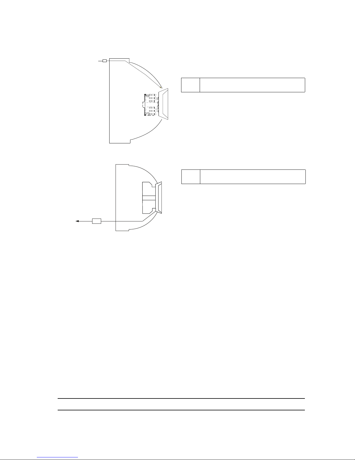
4.6. Compensation air diagram
25 : The compensation air prevents any
contamination of the inner shaping air shroud
and is controlled via a remote regulator.
4.7. Turbine exhaust diagram
25
Compensation air - Dia. 6 x 8 - Polyamide
421
Turbine exhaust - Dia. 8 x 10 -
Polyamide
DES01022
25
OD 5/16" NYLON
421
Page 27

Index revision : C - November 2017 27 7030
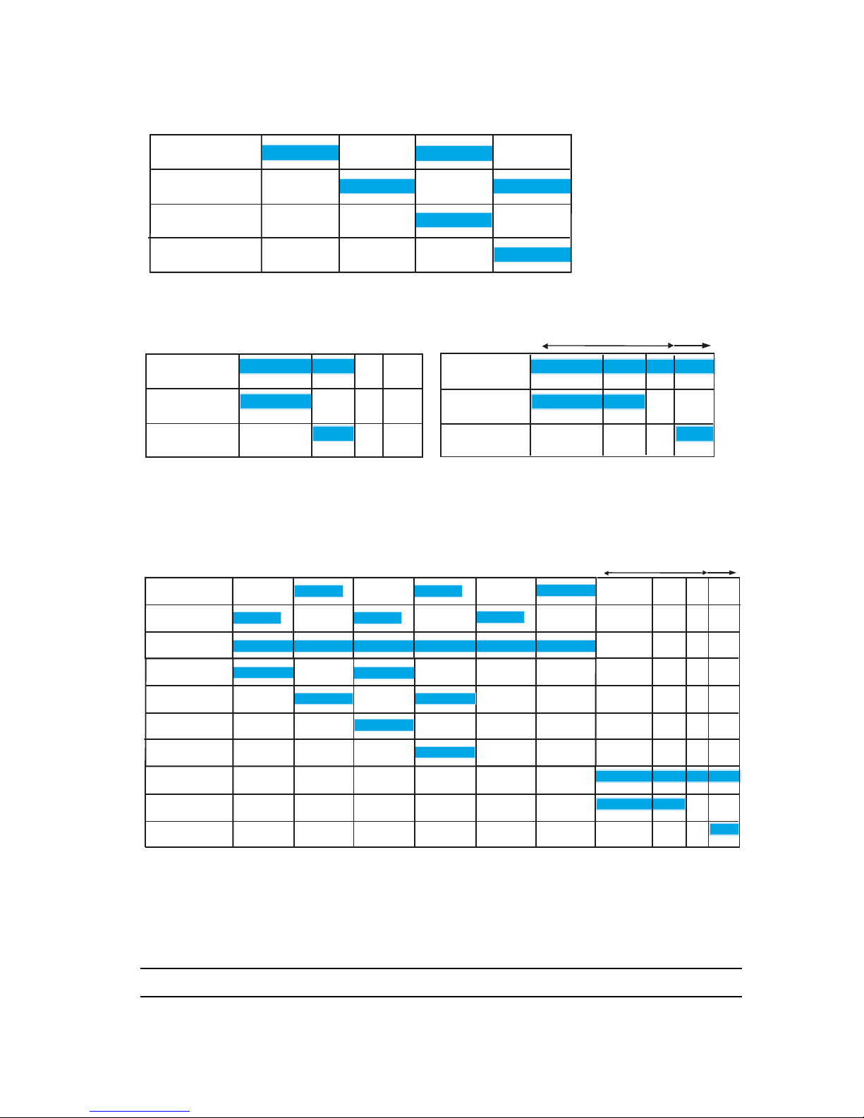
4.8. Colour change and rinsing cycles
Example of atomizer integration
• Standard conditions: 6 bar, air, solvent and paint.
• Colour change block and rinsing block operated 1 to 1.5 metres away from atomizer.
PV31PV31
PV32PV32
PV11PV11
11
41
32
31
PV41PV41
Air PV
- bell cup
Solvent PV
- bell cup
Solvent PV
- injector
rinsing
Colour change
block
Air PV
Solvent PV
Colours
Flow-rate adjustment restrictor (250 cc/min)
Flow-rate adjustment restrictor (300 cc/min)
Air PV
- injector
rinsing
0
1 2
3
4
5
6
DES01056
Air PV - Colour
change block
Solvent PV - Colour
change block
Seconds
Rinsing supply circuit only
Dump valve
PV 41
Page 28
Index revision : C - November 2017 28 7030
• Normal paint flow rate with valve activated: 150 cc/min
• X: Time required for the paint to flow from the colour change block to the bell cup.
• Y: Time required for paint to leave the bell cup.
• Recommended solvent flow rate for injector: 300 cc/min
• Recommended solvent flow rate for bell cup rinsing: 250 cc/min
• Always use restrictors if the flow rate exceeds the values above.
• The final pneumatic pulse clears and dries the rinsing circuit for the outside of the bell cup
in order to prevent any solvent being sprayed.
0
1 2
3
4
Rinsing bell cup only
Solvent PV
- injector rinsing
Air PV
- injector rinsing
Solvent PV- bell cup
rinsing
Air PV- bell cup
Seconds
DES01057
0 1 2 2.5
1.6
0
X
Y
Paint PV - Colour
change block
PV 11
Lower outlet
0.5 to 1 bar
Lower outlet
0.5 to 1 bar
Seconds
Option
Example of start-up cycle
Standard
Seconds
PV 11
Paint PV - Colour
change block
Dump valve
PV 41
Dump valve
PV 41
0
1 2
3
4
5
6
X
Y
Seconds
Colour change cycle
Air PV - Colour
change block
Solvent PV Colour change
Dump valve
PV 41
Solvent PV
- injector rinsing
Air PV
- bell cup rinsing
Solvent PV
- bell cup rinsing
Air PV
- injector rinsing
PV - colour on
colour change
Dump valve
PV 41
PV 11
Page 29
Index revision : C - November 2017 29 7030
5. Maintenance
5.1. Shut-down and start-up procedures
Important recommendations
Comply with the air settings given in Section 3.2.
The rotor and stator become inoperable if the bearing air is cut off during rotation.
The bearing air pressure must be at least 6 bar at the quick-disconnect plate.
(*For hose lengths greater than 4.5 m, the correct air pressure value is determined by taking the
measurement at the quick-disconnect plate).
Check that the speed regulating module transmits a signal.
5.1.1. Shut-down Procedure
Important steps to follow:
• Step 1: Stop spraying (PV 51 shut)
• Step 2: Switch off the high-voltage power supply,
• Step 3: Perform a circuit rinse cycle*,
• Step 4: Cut off the shaping air,
• Step 5: Cut off turbine rotation air and wait until the turbine comes to a complete stop (0
rpm),
• Step 6: Cut off the bearing air.
WARNING : * The rinsing cycle must end with a compressed air seque nce, cir cuits 31,3 2 and 3 6
must be purged and dried before restarting the high voltage.
WARNING : The turbine must never be stopped by cutting off the bearing air supply.
Wait until the turbine has come to a complete stop before cutting off the bearing
air.
5.1.2. Start-up Procedure
Important steps to follow:
• Step 1: Switch on the bearing air supply (6 bar),
• Step 2: Start up turbine rotation,
• Step 3: Switch on the shaping air supply,
• Step 4: Switch on the high voltage supply,
• Step 5: Start up atomisation.
Page 30
Index revision : C - November 2017 30 7030
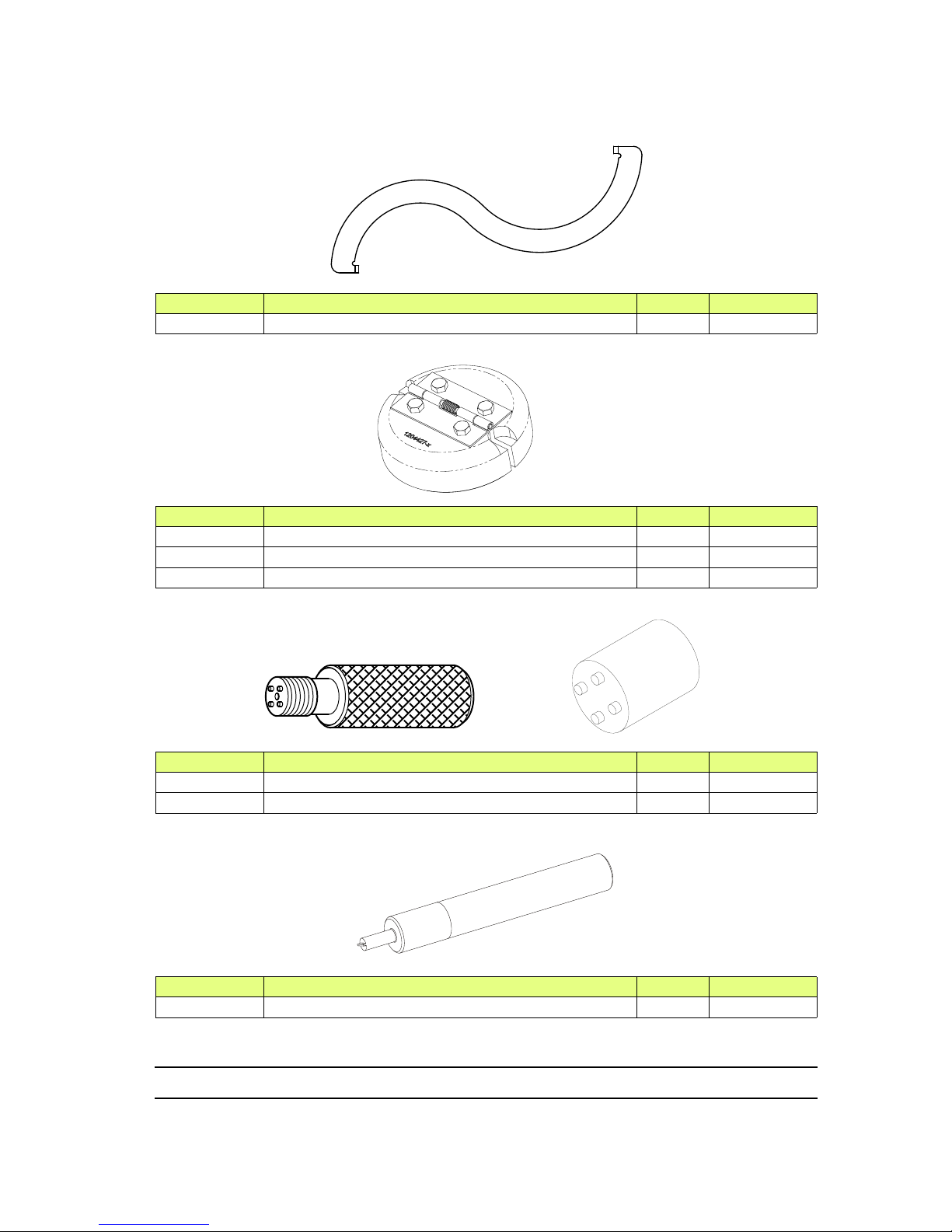
5.2. Tools
Part number Description Qty Unit of sale
1308689 Outer cover removal/reassembly tool 1 1
Part number Description Qty Unit of sale
1204427 Removal tool for magnetic bell cup 65 EC 1 1
900000803 Removal tool for magnetic bell cup 50 EC - 1
900000804 Removal tool for magnetic bell cup 35 EC - 1
Part number Description Qty Unit of sale
1303689 Microvalve removal/reassembly tool 1 1
1403478 Automatic microvalve tightening tool 1 1
Part number Description Qty Unit of sale
900002675 Placebo resistor assembling tool 1 1
DES01023
DES02870
DES01673
Page 31
Index revision : C - November 2017 31 7030
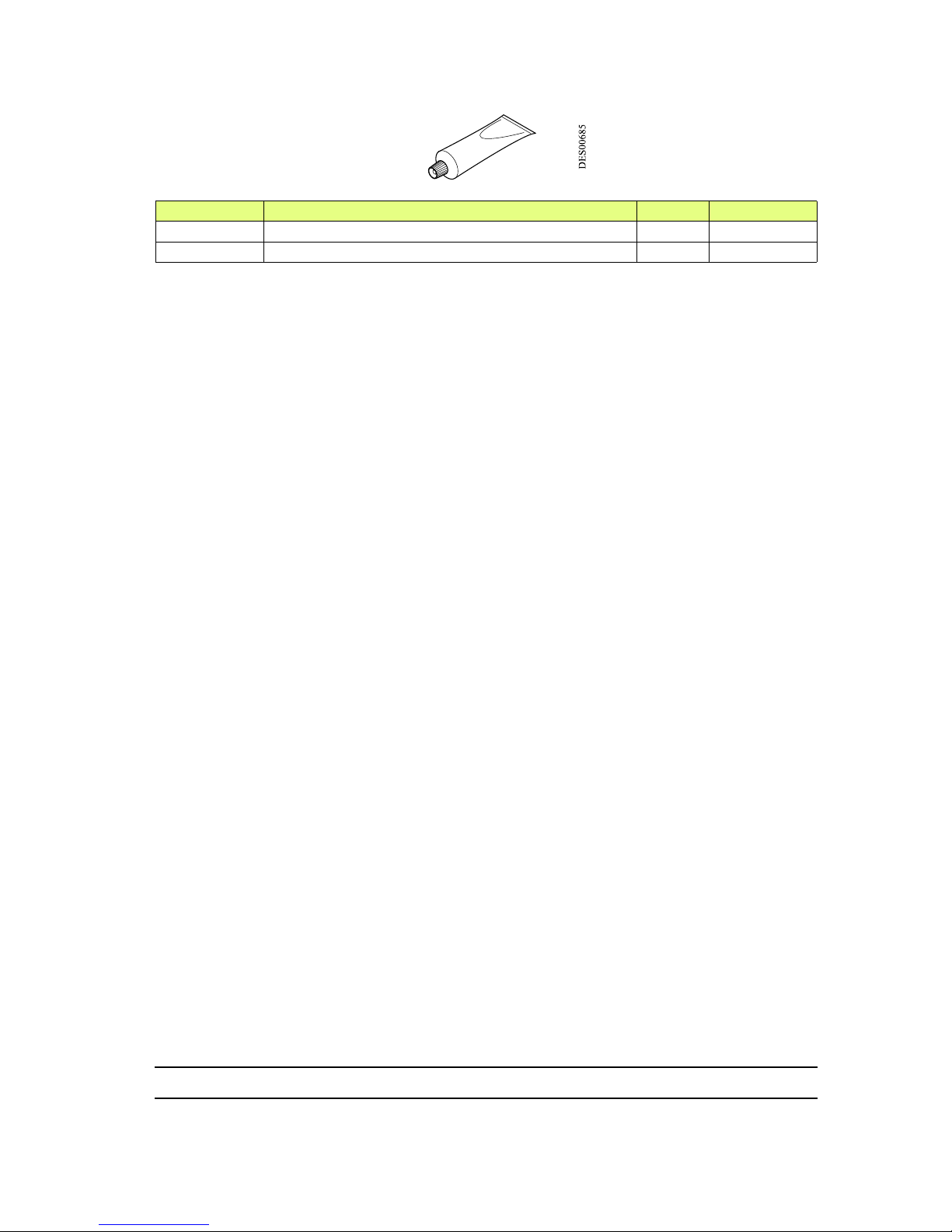
Part number Description Qty Unit of sale
H1GMIN017 Vaseline (100 ml) 1 1
H1GSYN037 Dielectric grease (100 ml) 1 1
Page 32

Index revision : C - November 2017 32 7030
5.3. Installing the Atomizer
For installation rules: see § 1.4.1 page 10.
• Step 1: Secure the support tube onto the painting apparatus using the securing nut.
• Step 2: Position the placebo assembly (with high voltage cable) in the atomizer sheath.
Lock placebo in place using the M 4x 10 screw, but do not fully tighten.
• Step 3: Connect air and product hoses to the manifold block.
WARNING : The 36 hose (4/6 PTFE) must first be sheathed with a 7/10 PTFE hose, the paint (11)
and dump (41) hoses (5/8 PTFE) by a 9/12 PTFE hose. Screw a sealing union at each end
of the sheath (P/N 910006017 for the 36 hose and P/N 910006552 for 11 and 41 hoses).
Total
sheath length should be approximately 5 cm less than the hose length
. The product hose
(5/8 PTFE) must also be sheathed with a 9/12 PTFE hose.
• Thread the hoses and high voltage cable through the support tube.
• Secure atomizer PPH 308 to the support tube with four M 8 x 30 screws.
• Screw the cover on to the atomizer.
• Fit the shaping air shroud, outer cover and bell cup.
Page 33

Index revision : C - November 2017 33 7030
6. Atomizer Maintenance
WARNING : These operations are to be performed only by trained persons.
6.1. Removing and re-installing the PPH 308
6.1.1. Disassembly
Rinse the PPH 308 before disassembly.
• Switch off the high-voltage power supply.
• Unlock the cover with the special tool (P/N 1308689).
• Unscrew and remove the cover.
• Loosen the screw that lock the placebo into its sheath (see § 2 page 17).
• Disconnect all hoses entering the Manifold block and 1 PV block (except hoses
connected between the 1 PV block and Manifold block).
• Loosen the 4 screws securing PPH 308 to holder.
WARNING : Do not remove the clamps from the MANIFOLD block to make sure they are not lost.
6.1.2. Reassembly
• Secure PPH 308 to support with the 4 screws.
• Reconnect all hoses to the MANIFOLD block and 1 PV block.
• Manually refit the cover and lock with the special tool (P/N 1308689).
6.2. Bell cups
For assembly and disassembly instructions see RT Nr 6285
6.3. Shaping air assembly (shroud and cover)
For assembly and disassembly instructions for the shaping air assembly see RT Nr 6285
6.4. Turbine
see RT Nr 6350 see attached manual.
Page 34
Index revision : C - November 2017 34 7030
6.5. Injector holder
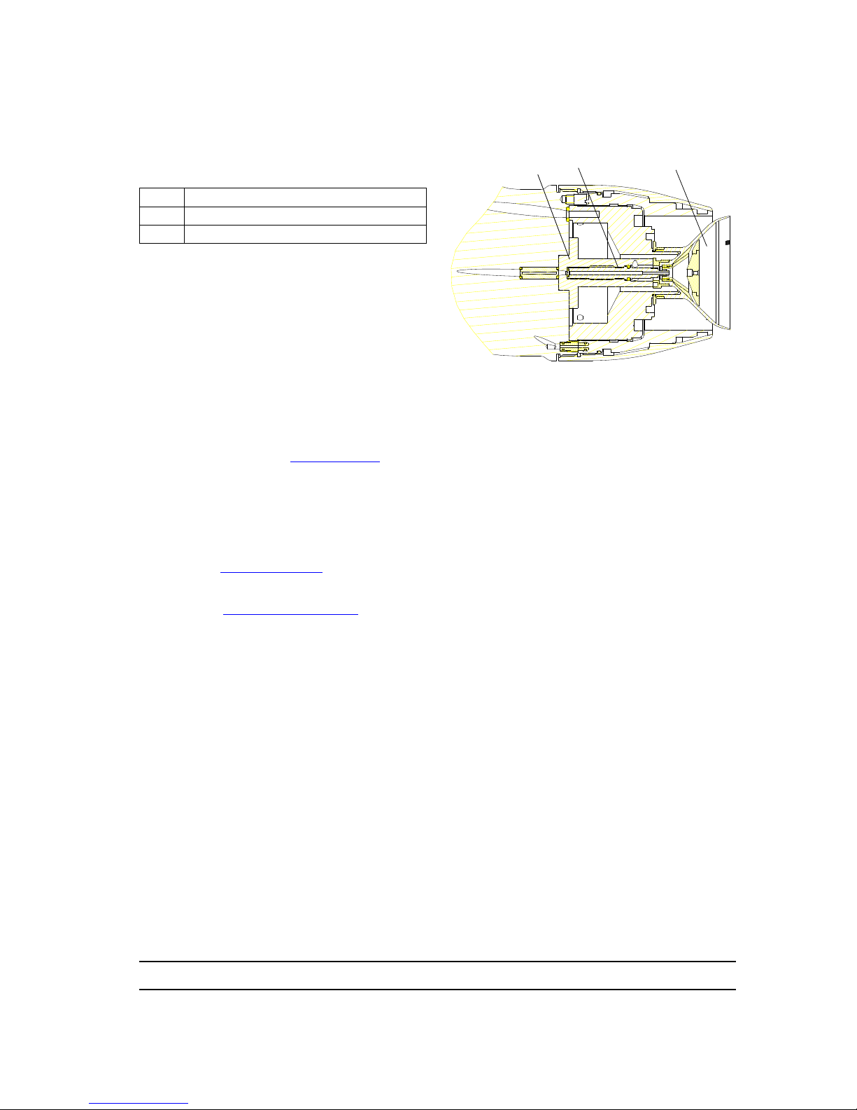
The injector holder is secured to the body of the PPH 308 by three M3 x 10 screws.
Its positioning pin ensures correct positioning.
6.6. Injector
6.6.1. Disassembly
• Switch off the machine.
• Remove bell cup (see RT Nr 6285).
• Remove outer cover.
• Remove shaping air shroud.
• Use a 2.5 mm Allen key to remove the five screws securing the turbine. Remove turbine.
• Use a 2.5 mm Allen key to remove the three screws securing the injector holder.
• Unscrew the injector (clockwise) using a 5 mm open-ended spanner, and remove it
carefully, to avoid damaging the injector and its two o-rings.
• Clean (see § 7 page 39).
6.6.2. Reassembly
• Clean (see § 7.2.3 page 42) the components and check their condition. Replace if
necessary.
• Insert the microphone seals into the manifold block.
• Put in place the injector holder with the aligment pin and tighten the three screws using a
2.5 mm Allen key.
• Fit both seals on the injector.
• Place the injector on the injector holder and tigh ten anticlockwise (figur e 4) to a torque
of 3.5 Nm.
• Secure the turbine onto the elbow using the five screws and tighten to a torque of 1.5 Nm.
• Refit the shaping air shroud.
• Clip the bell cup onto the turbine.
• Put the outer cover in place, manually t ighten then complete the tightening using the
special tool (P/N 1308689).
• Reconnect the power supply.
1 Injector holder
2 Injector
3 Bell cup
1
2 3
Page 35

Index revision : C - November 2017 35 7030
6.7. 1 PV Block and Manifold Block
6.7.1. Disassembly
• Remove PPH 308.
• Loosen the screw securing the 1 PV block onto the tie-rod.
• Disconnect the hoses between 1 PV block and Manifold block.
• Uncrew the tie-rod (see § 2 page 17).
• Unscrew tie-rod from Manifold block.
• Extract tie-rod from 1 PV block.
• If necessary, remove Manifold block restrictor (this requires the injector / injector holder
assembly to have been removed).
6.7.2. Reassembly
• Refit or replace the restrictor, depending on the product viscosity.
• Check the condition of the Manifold block comp onents (seals, solvent nozzle, coupling)
and change if required.
Check that there are no cracks on the 1PV block and especially around fitting 31.
WARNING : If the plastic coupling is replaced, PTFE tape will need to be wrapped around the
thread of the new plastic coupling (2 to 3 turns approx). Beware to avoid
overlapping the tape onto the coupling surface.
• Check that all seals are in place on the Manifold block.
• Insert tie-rod into 1 PV block and screw onto Manifold block.
• Lock tie-rod to support, tightening the screw fully in.
• Connect the hoses between 1 PV block and Manifold block.
• Lock 1 PV block to tie-rod, by tightening the nylon screw M5 x 10.
6.8. Microvalves
see RT Nr 6021
Page 36
Index revision : C - November 2017 36 7030
6.9. High Voltage Connection
6.9.1. Preparing the high voltage connection
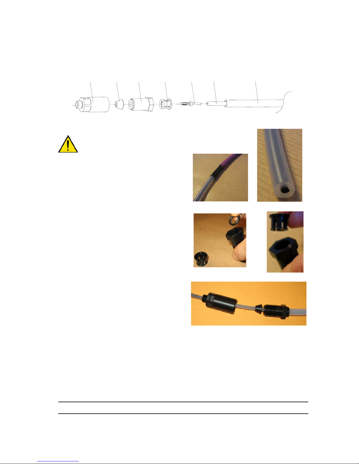
WARNING : Ensure that insulation is not
damaged. Any scratch or start of a cut on the
surface of the insulating material will result in
breakdown of the high voltage cable.
• Step 1: Strip back approximately 22.5 cm of
the purple insulation from high voltage
cable with a wire stripper. A “Stanley knife”
type cutting tool must not be used.
Next strip back approximately 19 cm of the
semi-conductive sheath (black sleeve)
and cut it with cutting pliers.
• Step 2: Insert seal and clamp into the nut.
• Step 3: Slide the nut assembly, split cone
and the cable-securing adapter onto the
cable. Then screw the nut onto the
adapter.
DES03696
Cable-securing
adapter
High voltage
cable
Supporting
Nut
Split
cone
End fitting
Clamp Protective hose
Step 1
Step 2
Step 3
Page 37
Index revision : C - November 2017 37 7030
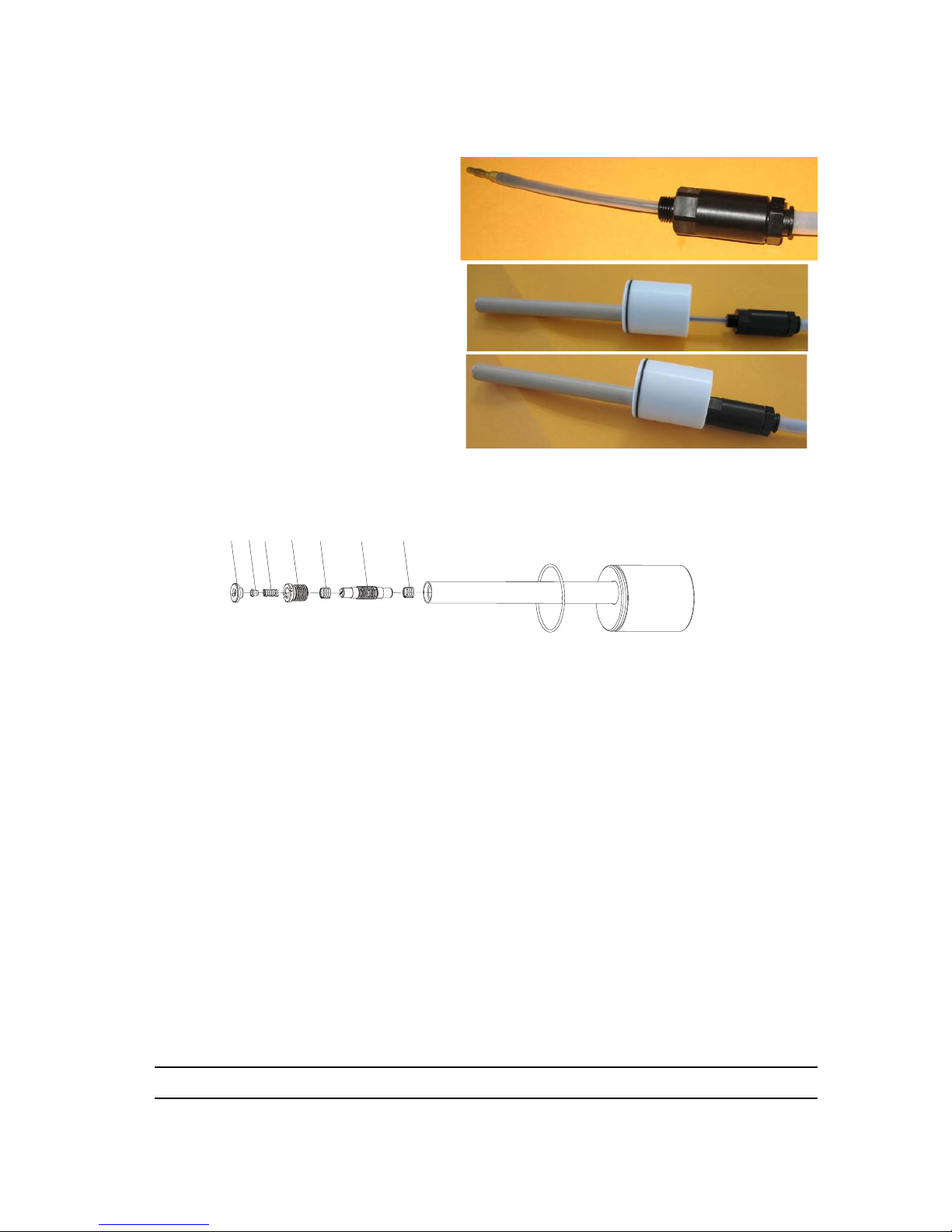
• Step 4: Insert the end fitting into the high voltage cable and screw on man ually, then with
a 6 mm open-ended spanner. Tighten fully.
• Step 5: Lubrication
• Coat the high voltage cable end
fitting with a layer of dielectric
lubricant.
• Step 6: Insert high voltage cable into
placebo and push it fully in.
• Step 7: Coat placebo thread with
IS401 adhesive and screw the cablesecuring adapter onto placebo.
6.9.2. Assembling / disassembling the internal resistor in the placebo
6.9.2.1. Disassembly
• Step 1: Unscrew high voltage cable stopper (item 1) with a flathead screwdriver.
• Step 2: Remove HV contact disc (item 2) and spring (item 3).
• Step 3: Unscrew HV contact housing (item 4).
• Step 4: Unscrew resistor (item 6) assembly with its two springs (item 5) with a flathead
screwdriver.
6.9.2.2. Reassembly
• Step 1: Coat all components with a thin layer of dielectric lubricant.
• Step 2: Assemble resistor (item 6) with its two springs (item 5), then screw into the placebo
using the special tool (P/N 900002675).
• Stage 3: Screw on HV contact housing (item 4).
• Step 4: Place spring and HV contact disc into the placebo.
• Step 5: Screw in high voltage cable stopper.
Step 5
Step 7
Step 6
DES03703
12345 6 5
Page 38

Index revision : C - November 2017 38 7030
6.9.3. Installation on atomizer
• Step 1: Insert placebo assembly into PPH 308 sheath (see § 8.1 page 43 item 10).
• Step 2: Screw in securing screw (see § 8.1 page 43 item 12), but do not fully tighten.
Page 39
Index revision : C - November 2017 39 7030
7. Cleaning Procedures
At regular intervals during frequent use, and at the end of each cycle:
• Stop the atomizer and switch off power supply.
Always refer to the health and safety instructions before carrying out any work see § 1.4 page 7.
WARNING : Always wear safety goggles.
Whenever solvent is handled, rubber gloves must be worn.
Work in a well-ventilated area whenever solvent is used.
WARNING : Prior to cleaning, it is essential to wipe the atomizer using a cloth soaked in water,
a soft brush and an approved cleaning product. Do not use a manual solvent gun.
WARNING : Do not soak the turbine in solvent.
The atomizer and its components must never be sprayed with solvent or water under any
circumstances, whether at high or low pressure.
WARNING : SAMES KREMLIN disadvises the use of anti-static plastic films to protect bodies
and insulating covers of the atomizers. These films are conductive and can short-circuit the high
voltage.
SAMES KREMLIN forbids the use of adhesives on the insulating parts of the atomizers. The
glue of the adhesives is conductive and thus can short-circuit the high voltage.
SAMES KREMLIN also forbids the use of absorbent textile cover to protect bodies and insulating covers of atomizers. Textile covers retain the cleaning products and paint what can generate problems of high voltage (drilling, ionization, degradation of the material...).
Thus, SAMES KREMLIN recommends the use of insulating grease for protection of the
atomizers.
In any case, insulating protection means must be used to prevent the slightest risk of current
overconsumption.
This is why, insulating protection means must be renewed on a regular basis.
Procedure Components Frequency
A Outer cover, outside of bell cup 8 hours
B
Bell cup, shaping air shroud, outer cover, outside
of injector, outside of bell cup
120 hours
Page 40
Index revision : C - November 2017 40 7030
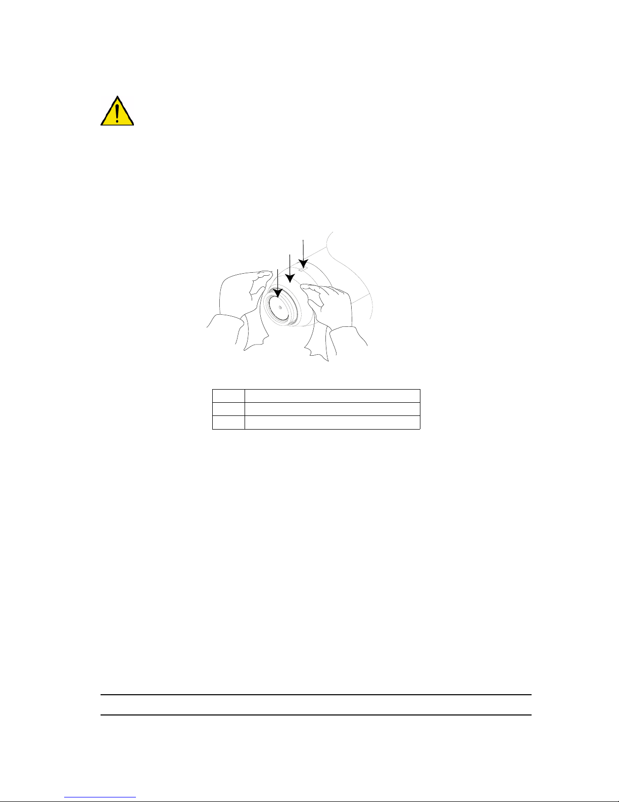
7.1. Procedure A
WARNING : Switch off the turbine. The bearing air and shaping air remains pressurised in order
to prevent solvent passing between the bell cup and shaping air shroud.
• Clean the outer cover and outside of the bell cup with a clean cloth, dampened with
solvent.
• Check that the grooves on the outer cover are clean.
• Dry carefully with a clean, dry cloth.
1 Bell cup
2 Outer cover
3 Grooves on outer cover
DES02097
1
2
3
Page 41
Index revision : C - November 2017 41 7030
7.2. Procedure B
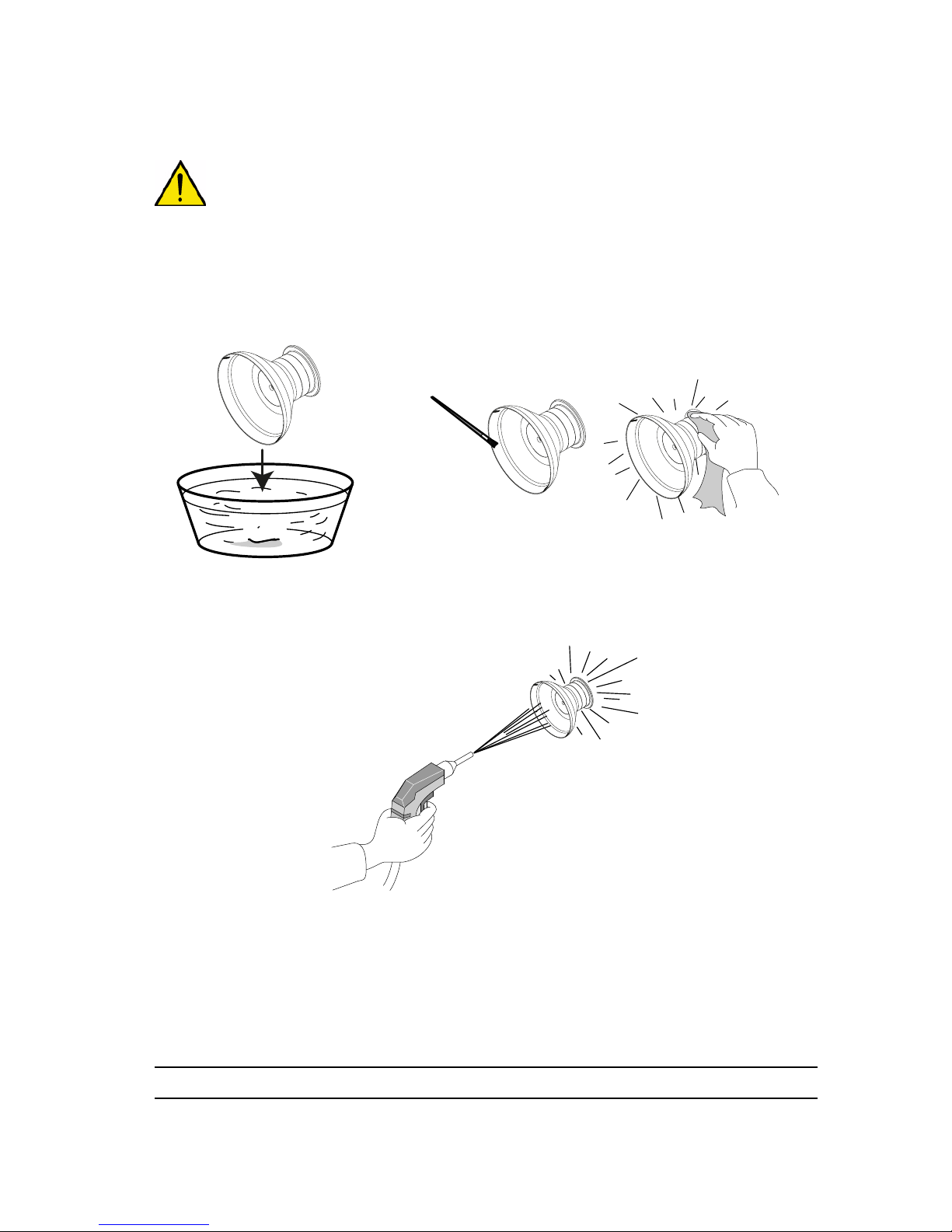
WARNING : Stop the turbine and cut off the shaping air
7.2.1. Bell cup
• Remove the bell cup using the specific tool.
• Leave the bell cup soaking in solvent for one hour then clean with a clean cloth and soft
brush.
• Dry carefully with compressed air.
DES02662
DES02663
Solvent
Page 42
Index revision : C - November 2017 42 7030
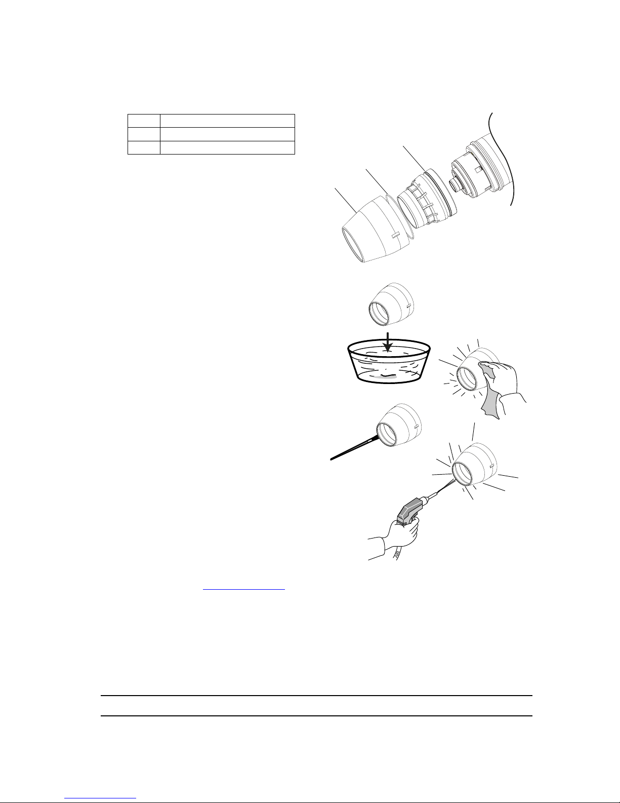
7.2.2. Outer cover
• Remove the shaping air assembly
• Step 2: Leave the outer cover to soak in
solvent for one hour then clean the outer
and inner surface with a cloth soaked in
solvent.
• Step 3: Clean all holes on the front of the
outer cover with a nylon brush.
• Step 4: Dry carefully with compressed air,
particularly focussing on the holes, to
ensure any paint residue is removed, then
wipe with a clean, dry cloth.
• Step 5: Check the condition of the inner
shaping air shroud and, if necessary, clean
it with a cloth soaked in solvent.
7.2.3. Injector and Injector Holder
• Remove injector see § 6.6 page 34
• Leave to soak for one hour in MEK solvent (methylethylketone).
• Dry carefully with compressed air.
• Reassemble in reverse order.
1 Outer cover
2 O-ring
3 Shaping air shroud
1
2
3
DES03378
Solvent
Page 43
Index revision : C - November 2017 43 7030
8. Spare Parts List
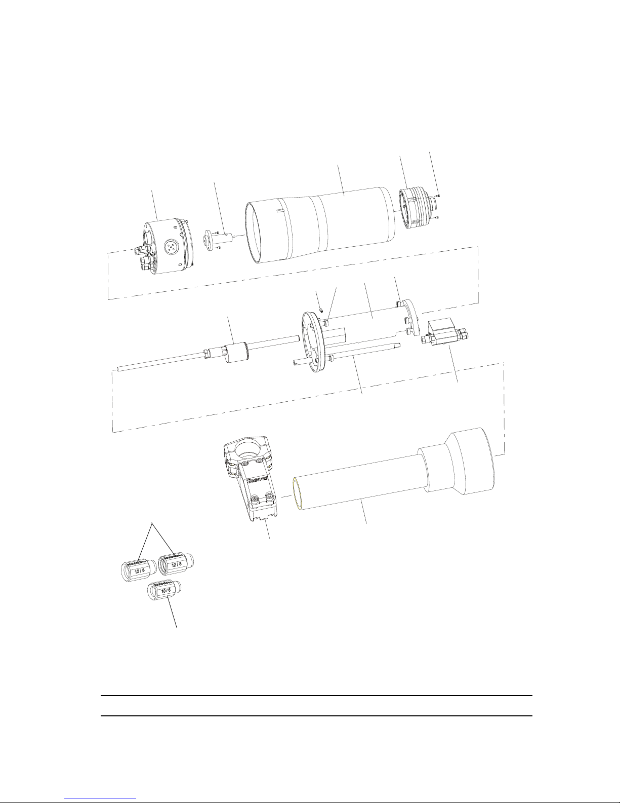
8.1. Single-circuit PPH 308 for solvent-based paints of resistivity 0.5 < ρ ≤ 6 MΩ.cm
Bell cup and shaping air assembly not included.
DES04336
1
2
3
4
5
6
7
8
9
10
11
12
13
14
15
16
Page 44
Index revision : C - November 2017 44 7030
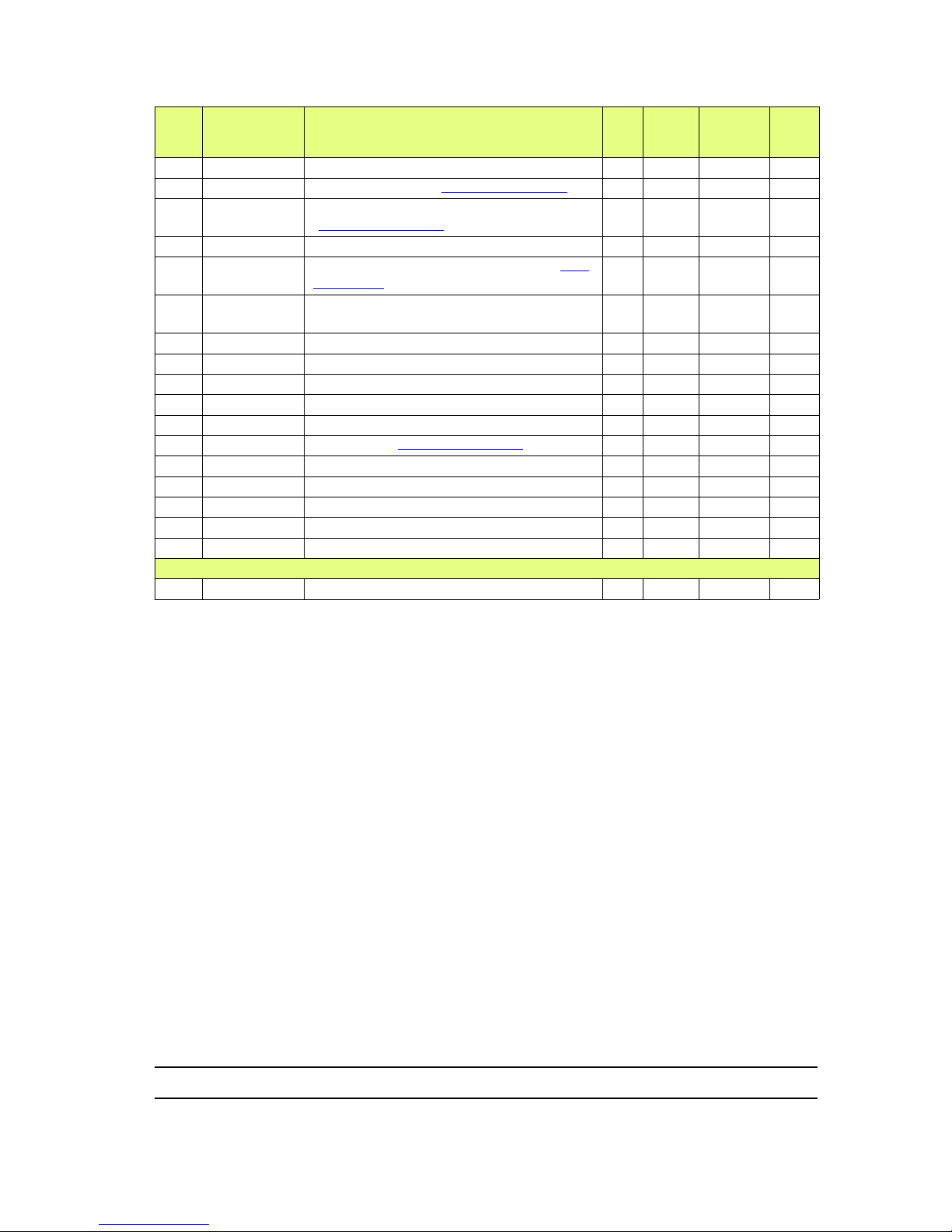
Item Part number Description Qty
Unit
of
sale
First
priority
Wear
910003350 Single-circuit PPH 308 without regulator 1 1 - -
1 910003632 MANIFOLD block (see § 8.3 page 46) 1 1 X
2 910001130
Injector / Injector holder assy
(see § 8.4 page 48)
1 1 X
3 910003398 Cover 1 1 - -
4 910000295
S6 Turbine with magnetic bell cup (see
RT Nr 6350)
1 1 X
5 X4FVSY067
CHC (Allen head) screws M5x20 (stainless steel)
5 1 - -
6 910003213 PPH 308 ATEX Placebo 1 1 X
7 X9NSFA118 Headless screws, C M4 x 10 (nylon) 1 1 - 8 X9SVCB285 Screws, C M 8 x 50 (nylon + glass fibre) 4 1 X
9 1202048 Sheath for HVU placebo 1 1 - 10 X9SVCB283 Screws, C M 8 x 50 (nylon + glass fibre) 4 1 X
11 910005997 1 PV block (see § 8.2 page 45). 1 1 X
12 1405874 Tie rod for 2 PV block 1 1 - 13 1203616 PPH 308 Tube holder - D:63 1 1 - 14 1204441 Nut for tube 1 1 - 15 910006552 Sealing screwed union for 12/8-hose 2 1 - X
16 910006017 Sealing screwed union for 10/6-hose 1 1 - X
Not shown
- 910003399 Grounding kit 1 1 - -
Page 45
Index revision : C - November 2017 45 7030
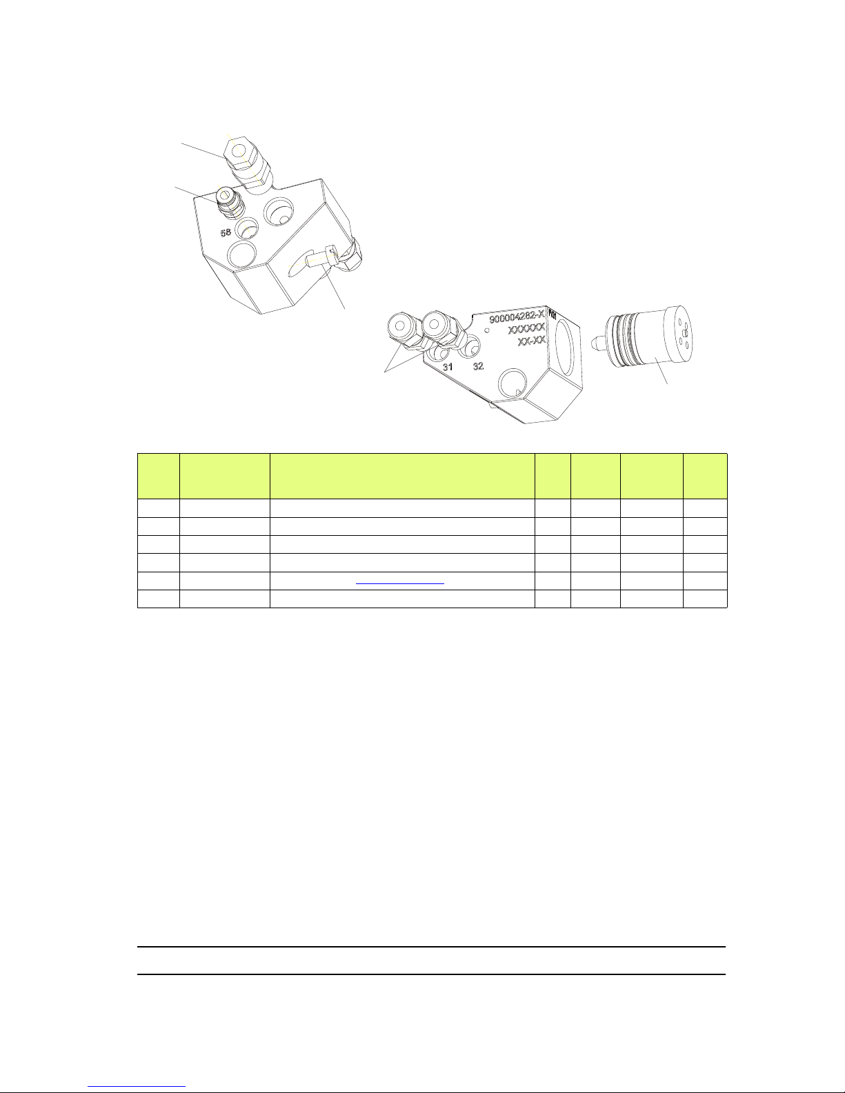
8.2. 1 PV Block
Item Part number Description Qty
Unit
of
sale
First
priority
Wear
910005997 1 PV Block 1 1 X
1 F6RPUK317 Male straight union 1/4 BSP for 4/6 hose 1 1 X
2 F6RLUS268 Male union 1 1 X
3 X9NVCB181 Nylon screw C M 5 x 10 1 1 X
4 1507375 Microvalve (see RT Nr 6021) 1 1 X
5 F6RPUQ062 Male union, 4 1/8” 2 1 X
DES04165
1
2
3
4
5
Page 46
Index revision : C - November 2017 46 7030
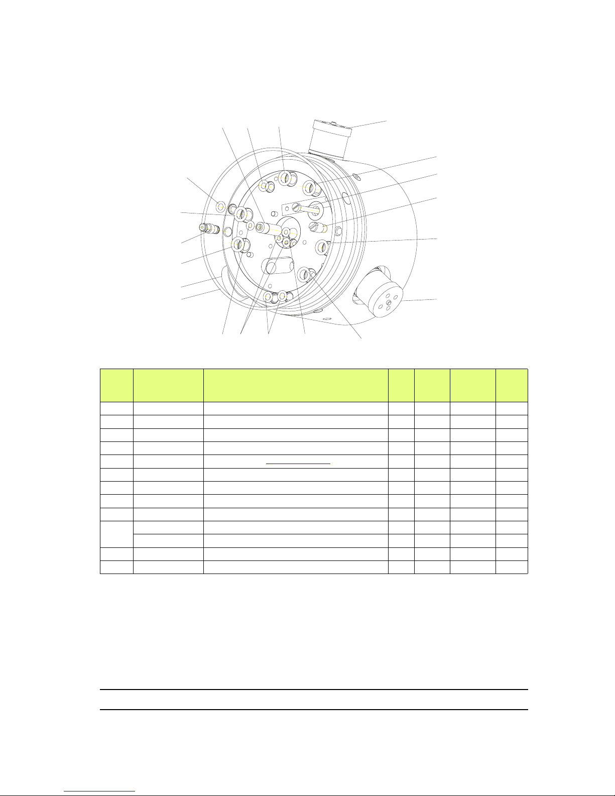
8.3. MANIFOLD Block
Item Part number Description Qty
Unit
of
sale
First
priority
Wear
910003632 Manifold block 1 1 X
1 1405931 Slotted screw, C M3 x 50 (brass) 1 1 - 2 1402691 Cover positioning device 1 1 - 3 J3STKL078 Chemically-inert O-ring 6 1 X
4 1507375 Microvalve (see RT Nr 6021) 3 1 X
5 J3STKL002 Chemically-inert O-ring 2 1 X
6 J3STKL039 Chemically-inert O-ring 3 1 X
7 J3STKL026 Chemically-inert O-ring 2 1 X
8 J2FENV638 O-ring 1 1 X
9
1519555 Solvent pipette assembly 1 1 - -
J3STKL027 Chemically-inert O-ring 2 1 X
10 640403 Restrictor - Dia. 1.2 1 1 X
11 J3STKL035 Chemically-inert O-ring 1 1 X
DES04171
1
2
3
4
3
4
3
11
10
3
56
7
5
8
4
3
9
3
6
Page 47
Index revision : C - November 2017 47 7030
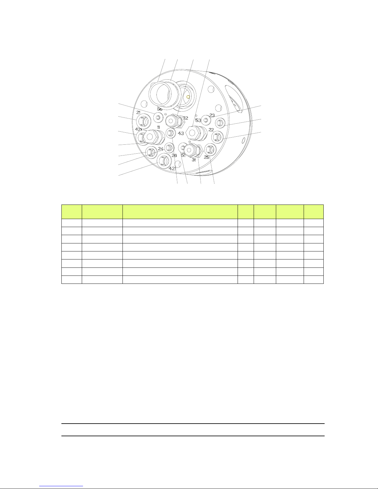
Item Part number Description Qty
Unit of
sale
First
priority
Wear
12 449707 Spacer 1 1 - 13 J2FTCF051 O-ring 1 2 X
14 F6RPUQ062 Male union 2 1 - X
15 910001739 1/4 Rack coupling for 5/8 hose 2 1 X
16 F6RXZG081 Stainless steel clamp and seal 3 1 - 17 F6RXZG082 Stainless steel clamp and seal 3 1 - 18 F6RXZG083 Stainless steel clamp and seal 3 1 - 19 F6RXZG084 Stainless steel clamp and seal 3 1 - -
DES04170
12 13 141415
15
16
16
16
17
17
17
18
18
18
19
19
19
Page 48
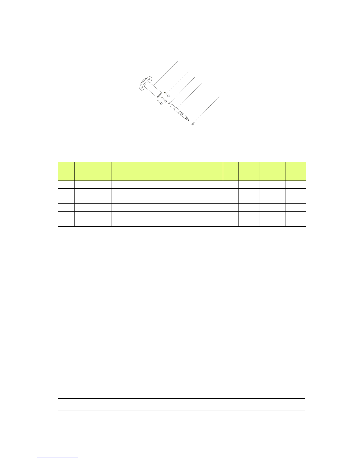
Index revision : C - November 2017 48 7030
8.4. Injector / Injector holder assembly
Item
Part number Description Qty
Unit
of
sale
First
priority
Wear
910001130 Injector / Injector holder assembly 1 1 X
1 738354 Injector holder 1 1 - 2 X4FVSY067 Stainless steel screw C M 3 x 10 3 1 - 3 J3STKL014 O-ring - chemically inert 1 1 X
4 738635 Injector Dia: 1,8 1 1 X
5 J3STKL005 O-ring - chemically inert 1 1 X
DES02117
1
2
3
4
5
Page 49
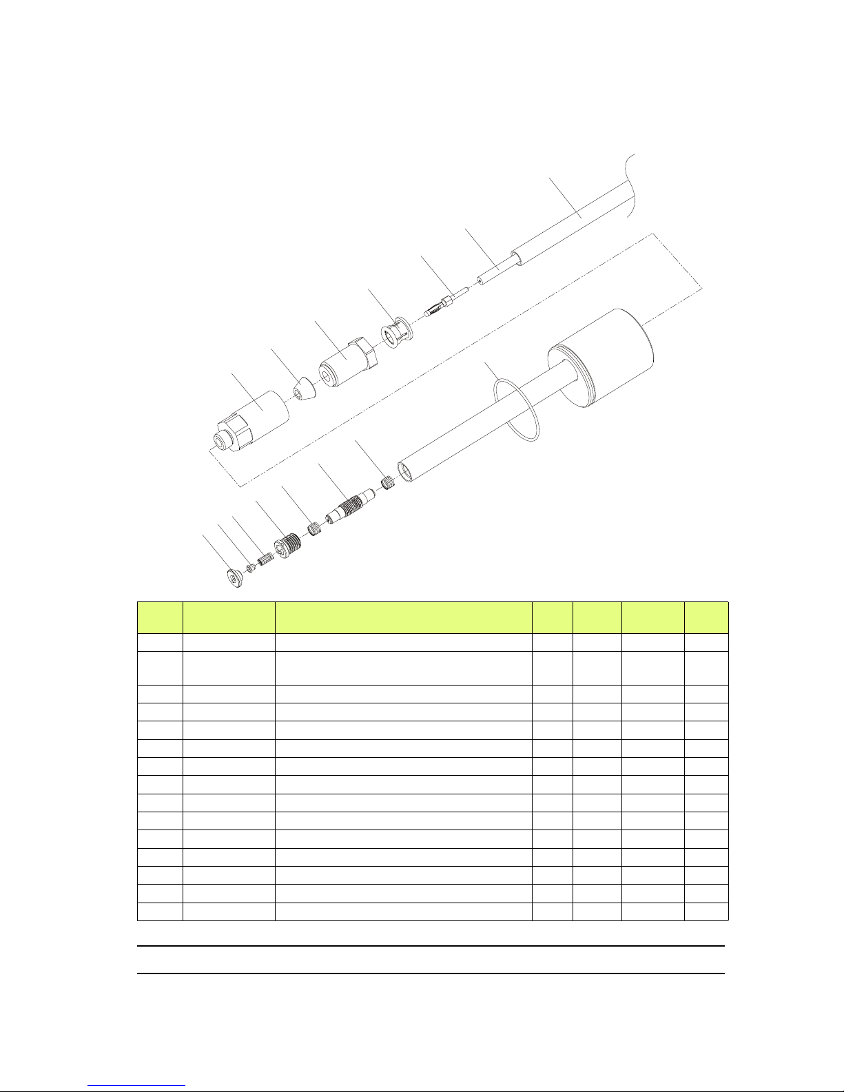
Index revision : C - November 2017 49 7030
8.5. Placebo and resistor
8.5.1. To connect to one PPH 308 atomizer
Item Part number Description Qty
Unit of
sale
First
priority
Wear
910003213 Placebo and resistor 1 1 X
1 U1CBBR057
Protective hose, HV cable, D:10/12
clear polyamide
9 m m - -
2 E2DAVD101 High voltage cable (100kV) 9 m m - 3 E4CSHT181 HV cable screw-on end-fitting 1 1 - 4 F6RXZG085 Stainless steel clamp and seal 1 1 - 5 1315058 Clamp nut 1 1 - 6 1411689 Split cone 1 1 - 7 900002154 Cable-securing adapter 1 1 - 8 548304 HV cable stopper 1 1 - 9 548303 HV contact disc 1 1 - -
10
Q2HRDC095
Spring 1 1 - 11 900002471 HV contact housing 1 1 - 12 200000004 Spring 2 1 - 13 1315102 22 Mohm Resistor 1 1 X
14 J2FTDF416 O-ring 1 1 X
DES03688
1
2
3
4
5
6
7
8
9
10
13
12
11
12
14
If the resistor requires replacement,
use the special tool (P/N 900002675) to screw the
new resistor into the placebo.
Page 50
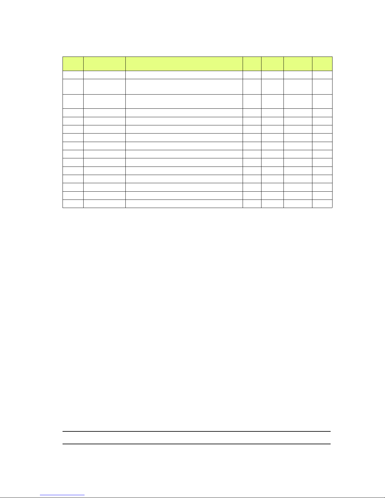
Index revision : C - November 2017 50 7030
8.5.2. To connect two PPH 308 atomizers to a single HVU (optional)
Item Part number Description Qty
Unit of
sale
First
priority
Wear
910003563 Placebo and resistor 1 1 X
1 U1CBBR057
Protective hose for HV cable, D:10/12
clear polyamide
4.25
m
m - -
2 E2DAVD101 High voltage cable (100kV)
4.25
m
m - -
3 E4CSHT181 HV cable screw-on end-fitting 1 1 - 4 F6RXZG085 Stainless steel clamp and seal 1 1 - 5 1315058 Clamp nut 1 1 - 6 1411689 Split cone 1 1 - 7 900002154 Cable-securing adapter 1 1 - 8 548304 HV cable stopper 1 1 - 9 548303 HV contact disc 1 1 - -
10
Q2HRDC095
Spring 1 1 - 11 900002471 HV contact housing 1 1 - 12 200000004 Spring 2 1 - 13 1315102 22 Mohm Resistor 1 1 X
14 J2FTDF416 O-ring - Viton 1 1 X
Page 51
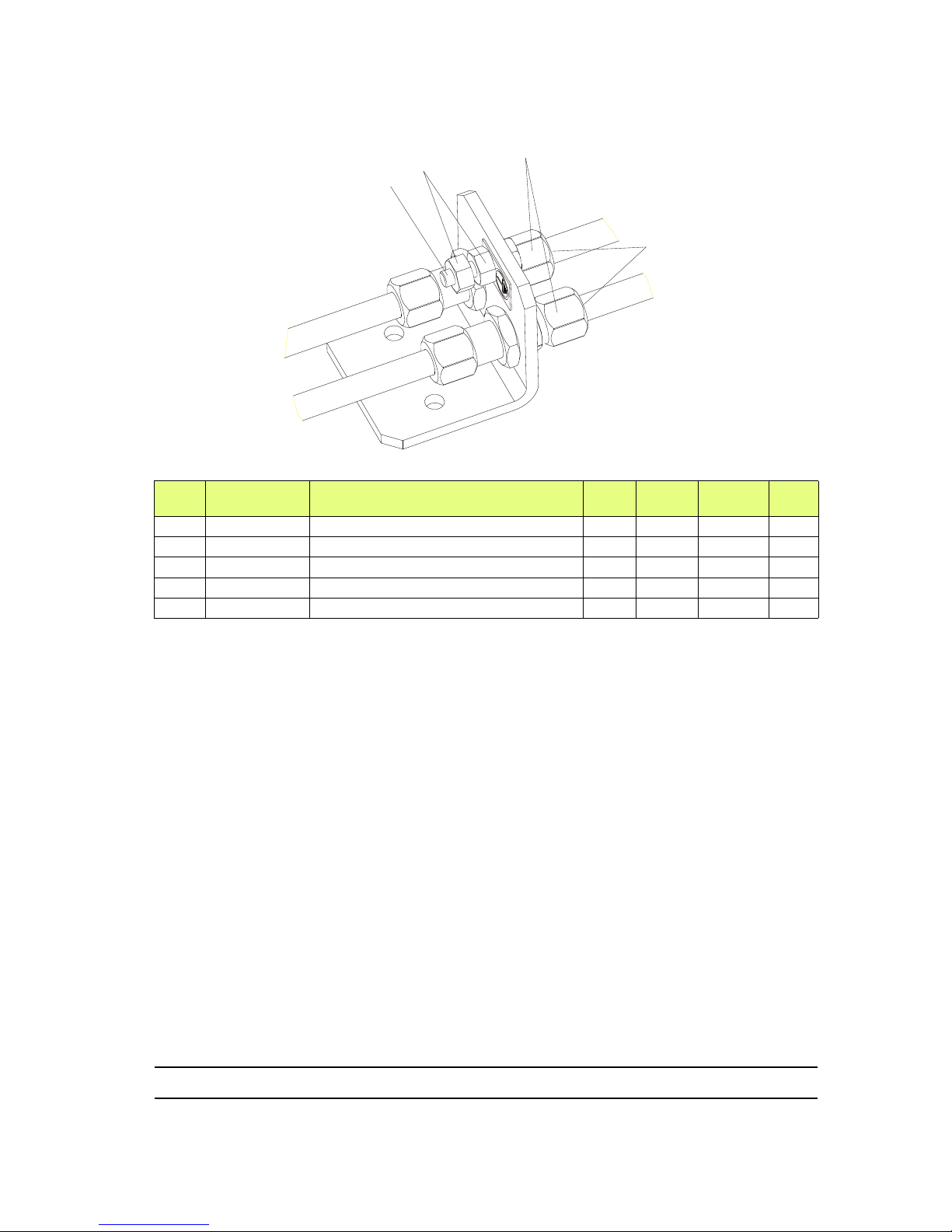
Index revision : C - November 2017 51 7030
8.6. Grounding kit
Item Part number Description Qty
Unit of
sale
First
priority
Wear
910003399 Grounding kit 1 1 - -
1 X7CVHA226 Bolt, H M6 x 20 (brass) 1 1 - 2 X7CEHU006 Nut, H M 6 (brass) 2 1 - 3 F6RXGQ056 Bulkhead union 2 1 - 4 F6RXZX061 Stainless steel sheath 4 1 - -
1
3
4
2
Page 52
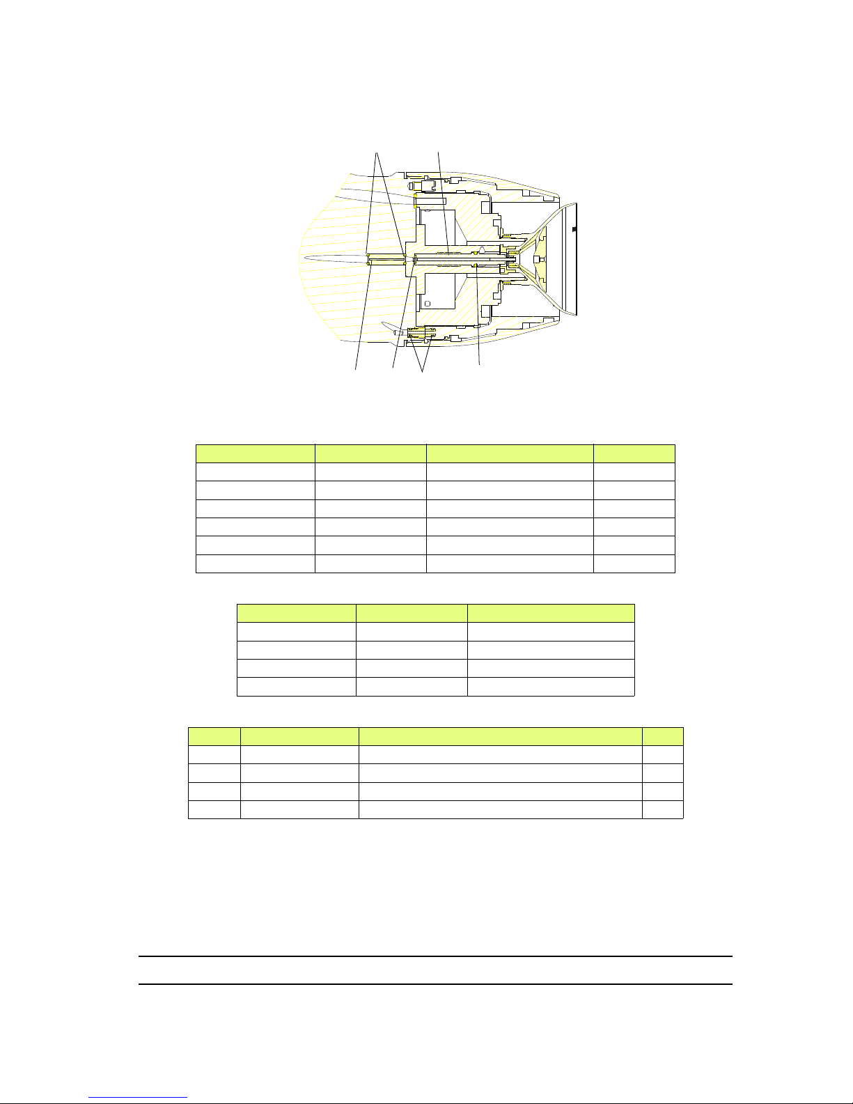
Index revision : C - November 2017 52 7030
8.7. Turbine, injector and restrictor seals
Part number Restrictor Number of grooves Colour
640400 D: 0.8 mm - Black
640401 D: 0.9 mm 1 Black
640402 D: 1.0 mm 2 Black
640403 D: 1.2 mm - White
640456 D: 1.5 mm 1 White
640464 D: 3.0 mm 2 White
Part number Injector Number of grooves
738632 D: 0.9 mm 738353 D: 1.2 mm 2
738634 D: 1.5 mm 3
738635 D: 1.8 mm 4
Item Part number Description Qty
1 J3STKL005 Chemically-inert O-ring 1
2 J3STKL014 Chemically-inert O-ring 1
3 J3STKL002 Chemically-inert O-ring 2
4 J3STKL027 Chemically-inert O-ring 2
DES03373
1
2
3
4
Restrictor
Injector
 Loading...