


Index revision : A 1 7118
User manual
SAMES KREMLIN SAS - 13, Chemin de Malacher - 38240 MEYLAN - FRANCE
Tel. 33 (0)4 76 41 60 60 - www.sames-kremlin.com
Nanogun Airmix
®
H2O
GNM 6080

Index revision : A 2 7118
This document may not be disclosed or copied, in any form, and its content may not be used
or disclosed, without the explicit written authorisation of SAMES
KREMLIN.
The descriptions and characteristics contained in this document may be modified without prior
notice.
© SAMES KREMLIN 2017
WARNING : SAMES KREMLIN SAS has been declared as a training centre with the
Ministry of employment.
Our company organises training courses providing the indispensable know-how
for the installation and maintenance of our equipment all year long.
A catalogue is available on request. Select the training programme, type of
learning method and skills you need from our range, to meet your production
targets.
These training courses can be organised on the premises of your company or at
the training centre located at our head office in Meylan.
Training service:
Tel.: 33 (0)4 76 41 60 04
E-mail: formation-client@sames-kremlin.com
SAMES KREMLIN SAS has drafted this operating manual in French and mandated English, German, Spanish,
Italian and Portuguese translations.
The company declares reservations on all translations and refuses any liability with respect to these translated
documents.

Index revision : 3
Nanogun Airmix® H2O
GNM 6080
1. Product identification - - - - - - - - - - - - - - - - - - - - - - - - - - - - - - - - - - 5
1.1. Version identification . . . . . . . . . . . . . . . . . . . . . . . . . . . . . . . 5
1.1.1. On the gun barrel . . . . . . . . . . . . . . . . . . . . . . . . . . . . . . . . . . . . 5
1.1.2. On the lower part of the gun handle . . . . . . . . . . . . . . . . . . . . 5
1.2. GNM 6080 control module . . . . . . . . . . . . . . . . . . . . . . . . . . . 6
2. Health and safety guidelines - - - - - - - - - - - - - - - - - - - - - - - - - - - - 7
2.1. Regulations . . . . . . . . . . . . . . . . . . . . . . . . . . . . . . . . . . . . . . . 7
2.2. Installation rules . . . . . . . . . . . . . . . . . . . . . . . . . . . . . . . . . . . . 7
2.3. Rules of use . . . . . . . . . . . . . . . . . . . . . . . . . . . . . . . . . . . . . . . 8
2.4. Maintenance rules . . . . . . . . . . . . . . . . . . . . . . . . . . . . . . . . . 9
2.4.1. Products used . . . . . . . . . . . . . . . . . . . . . . . . . . . . . . . . . . . . . . 10
3. Description of spray gun and GNM 6080 control module- - - - - - 11
3.1. Functions available based on this gun . . . . . . . . . . . . . . . . 11
3.2. GNM 6080 control module . . . . . . . . . . . . . . . . . . . . . . . . . . 12
4. Technical characteristics - - - - - - - - - - - - - - - - - - - - - - - - - - - - - - 14
4.1. General characteristics of the guns . . . . . . . . . . . . . . . . . . 14
4.2. Flows . . . . . . . . . . . . . . . . . . . . . . . . . . . . . . . . . . . . . . . . . . . . 15
4.3. Characteristics of the GNM 6080 . . . . . . . . . . . . . . . . . . . . 16
4.4. Characteristics of the compressed air . . . . . . . . . . . . . . . . 16
5. Operations - - - - - - - - - - - - - - - - - - - - - - - - - - - - - - - - - - - - - - - - - 17
6. Specific tooling- - - - - - - - - - - - - - - - - - - - - - - - - - - - - - - - - - - - - - 18
6.1. Use of the multipurpose wrench . . . . . . . . . . . . . . . . . . . . . 20
7. Installation- - - - - - - - - - - - - - - - - - - - - - - - - - - - - - - - - - - - - - - - - - 21
8. Use - - - - - - - - - - - - - - - - - - - - - - - - - - - - - - - - - - - - - - - - - - - - - - - 22
8.1. Recommendations regarding the paint to be used . . . . 22
8.1.1. Viscosity . . . . . . . . . . . . . . . . . . . . . . . . . . . . . . . . . . . . . . . . . . . 22
8.1.2. Flash point . . . . . . . . . . . . . . . . . . . . . . . . . . . . . . . . . . . . . . . . . 22
8.2. Spraying rules . . . . . . . . . . . . . . . . . . . . . . . . . . . . . . . . . . . . . 23
9. Examples of poor equipment use- - - - - - - - - - - - - - - - - - - - - - - - 24
10. Maintenance - - - - - - - - - - - - - - - - - - - - - - - - - - - - - - - - - - - - - - 25
10.1. Summary table of preventive maintenance . . . . . . . . . . 25
10.2. Electro-pneumatic link . . . . . . . . . . . . . . . . . . . . . . . . . . . . 26
10.3. Paint hoses . . . . . . . . . . . . . . . . . . . . . . . . . . . . . . . . . . . . . . 27
10.4. Spraying head assembly . . . . . . . . . . . . . . . . . . . . . . . . . . 28
10.5. Replacement of the head electrode. . . . . . . . . . . . . . . . 29
10.6. Barrel . . . . . . . . . . . . . . . . . . . . . . . . . . . . . . . . . . . . . . . . . . . 32
10.7. Paint nozzle needle . . . . . . . . . . . . . . . . . . . . . . . . . . . . . . . 33
10.8. Switch . . . . . . . . . . . . . . . . . . . . . . . . . . . . . . . . . . . . . . . . . . 34
10.9. Trigger . . . . . . . . . . . . . . . . . . . . . . . . . . . . . . . . . . . . . . . . . . 34

Index revision : 4
10.10. Air valve . . . . . . . . . . . . . . . . . . . . . . . . . . . . . . . . . . . . . . . 35
10.10.1. Repairing of the air valve. . . . . . . . . . . . . . . . . . . . . . . . . . . 36
10.11. Fastening hook . . . . . . . . . . . . . . . . . . . . . . . . . . . . . . . . . 37
10.12. High-voltage cascade . . . . . . . . . . . . . . . . . . . . . . . . . . . 38
10.13. Barrel . . . . . . . . . . . . . . . . . . . . . . . . . . . . . . . . . . . . . . . . . . 39
10.14. Handle . . . . . . . . . . . . . . . . . . . . . . . . . . . . . . . . . . . . . . . . 40
10.15. Electrical diagrams . . . . . . . . . . . . . . . . . . . . . . . . . . . . . . 41
10.15.1. GNM 6080 / Nanogun Airspray Airmix® H2O connection
cable. . . . . . . . . . . . . . . . . . . . . . . . . . . . . . . . . . . . . . . . . . . . . . . . . . . 41
10.15.2. GNM 6080 trigger cord. . . . . . . . . . . . . . . . . . . . . . . . . . . . . 41
11. Cleaning- - - - - - - - - - - - - - - - - - - - - - - - - - - - - - - - - - - - - - - - - - 42
11.1. Cleaning of the product circuit . . . . . . . . . . . . . . . . . . . . 42
11.2. Cleaning of the gun . . . . . . . . . . . . . . . . . . . . . . . . . . . . . . 42
11.3. Hollow cone nozzle cleaning . . . . . . . . . . . . . . . . . . . . . . 43
11.4. Elimination of wastes . . . . . . . . . . . . . . . . . . . . . . . . . . . . . 44
11.5. Dismantling and Recycling . . . . . . . . . . . . . . . . . . . . . . . . 45
11.5.1. Nanogun Airmix® H2O. . . . . . . . . . . . . . . . . . . . . . . . . . . . . . . 45
11.5.2. GNM 6080 . . . . . . . . . . . . . . . . . . . . . . . . . . . . . . . . . . . . . . . . . 47
12. Common malfunctions and repairs - - - - - - - - - - - - - - - - - - - - - 48
13. Spare parts - - - - - - - - - - - - - - - - - - - - - - - - - - - - - - - - - - - - - - - - 50
13.1. Nanogun Airmix® H2O guns for water-based paint (LR) 50
13.1.1. The nozzles as an option. . . . . . . . . . . . . . . . . . . . . . . . . . . . . 52
13.1.2. Fitted head ring. . . . . . . . . . . . . . . . . . . . . . . . . . . . . . . . . . . . 53
13.1.3. Fitted head. . . . . . . . . . . . . . . . . . . . . . . . . . . . . . . . . . . . . . . . 53
13.2. Nanogun Airmix® H2O gun . . . . . . . . . . . . . . . . . . . . . . . . . 54
13.3. Equipped seat casing (flat spray only) . . . . . . . . . . . . . . . 57
13.4. Equipped adapter (flat spray only) . . . . . . . . . . . . . . . . . 57
13.5. Equipped barrel . . . . . . . . . . . . . . . . . . . . . . . . . . . . . . . . . 58
13.6. Equipped air valve and air valve Nut . . . . . . . . . . . . . . . . 59
13.7. Equipped nozzle needle . . . . . . . . . . . . . . . . . . . . . . . . . . 60
13.8. Electro-pneumatic coupling . . . . . . . . . . . . . . . . . . . . . . . 60
13.9. Paint hose . . . . . . . . . . . . . . . . . . . . . . . . . . . . . . . . . . . . . . 61
13.10. Nanogun Airmix® H2O seal kit . . . . . . . . . . . . . . . . . . . . . 62
13.11. Hollow cone kit (not available for North American
market) . . . . . . . . . . . . . . . . . . . . . . . . . . . . . . . . . . . . . . . . . . . . . 63
13.11.1. Equipped hollow cone seat casing . . . . . . . . . . . . . . . . . . 64
13.11.2. Procedure for changing from a flat spray
to a round spray . . . . . . . . . . . . . . . . . . . . . . . . . . . . . . . . . . . . . . . . . 65
13.12. GNM 6080 control module . . . . . . . . . . . . . . . . . . . . . . . . 66
13.13. Options for the Nanogun Airmix® H2O guns . . . . . . . . . 66
13.14. Appendices . . . . . . . . . . . . . . . . . . . . . . . . . . . . . . . . . . . . 67
13.14.1. Hose protection casing . . . . . . . . . . . . . . . . . . . . . . . . . . . . 67
13.14.2. Gun protective cover. . . . . . . . . . . . . . . . . . . . . . . . . . . . . . 67
13.14.3. Warning sign. . . . . . . . . . . . . . . . . . . . . . . . . . . . . . . . . . . . . . 67
13.14.4. Safety relief valve . . . . . . . . . . . . . . . . . . . . . . . . . . . . . . . . . 67

Index revision : A 5 7118
1. Product identification
The Nanogun Airmix® H2O gun markings will allow differentiating between the 120-bar and the
200-bar model configuration.
1.1. Version identification
1.1.1. On the gun barrel
The marking on the barrel is the same across the entire Nanogun Airmix® H2O range.
1.1.2. On the lower part of the gun handle
This marking combines, under a single number, the configurat ions of guns operating at the
same level of pressure generation.
Product pressure Versions of Nanogun Airmix® H2O
120 bar JP (flat spray)
200 bar JP (flat spray)
DES06782
Serial no.

Index revision : A 6 7118
1.2. GNM 6080 control module
The GNM 6080 control module has been installed outside of the “A TEX” zone.
Markings
Example: * 2014: Year of manufacturing
26: Week number
123: nth generator built during week 26.
WARNING : The Nanogun Airmix® H2O equipment are all compliant with the operational safety
standard (i.e. Standard EN13849, level SIL 1); maintaining this level of safety requires periodic
inspections of the equipment, at least once every 5 years or 15,000 hours of operations (which
ever comes first). This control step pertains to each of the electrical and electronic components
as well as to the set of very specific program(s); you should contact your subsidiary, distributor
or regular SAMES KREMLIN representative, who will inform you of the appropriate steps to
take.
DES05878
DES05879
Software version:
S/N:
EC marking
2014 26123 *
CSA marking
Software version:
S/N:
2014 26123 *

Index revision : A 7 7118
2. Health and safety guidelines
WARNING : This equipment may be hazardous if it is not used, disassembled and reassembled
in accordance with the rules indicated in this manual and in any applicable Euro
-
pean Standard or national safety regulations.
The warning sign summarising the safety rules (procedures and precautions) of the
present user’s manual must be placed in a visible location within the zone of the
coating product spraying station.
WARNING : The good working order of this equipment is only under warranty provided use of
original spare parts distributed by ”SAMES KREMLIN” company.
2.1. Regulations
The Nanogun Airmix® H2O gun must always be used under the set of conditions required by cur-
rent standards and rules as regards the application of paints and varnishes (see the Standards
and Directive EN 50.053 Directive, Part 1 ISO 12100, EN 1953 and 99/92/CE).
In Canada, the installation must comply with the Code "C22.1 Canadian Electrical Code, Part
I, Safety Standard for Electrical Installations
".
In the United States, the installation must comply with the Code "NFPA 70: National Electrical
Code
".
The Nanogun Airmix® H2O gun has been designed to operate within a 2nd-degree pollution
environment, as defined according to the Standard IEC-664-1.
2nd-degree pollution: Under normal use conditions, only non-conductive type pollution arises.
On a temporary basis, conduction caused by condensation may arise.
WARNING : Before using the Nanogun Airmix® H2O gun, be sure that all operators
• have received preliminary training by the SAMES KREMLIN, or by the Distributors it has
certified for this purpose.
• have read and understood the user’s manual as well as all installat ion and us e rules li sted
below.
It is incumbent upon the Operators’ Workshop Manager to ensure and verify that all operators
have read and understood the user’s manuals relative to peripheral electrical devices present
within the spraying perimeter.
2.2. Installation rules
• The hand-held electrostatic projection equipment can only be used in designated projection spots in accordance with Standard EN 12215 or under equivalent ventilation conditions.
• Install the equipment away from any explosive zone.
• Servo-control the control module start-up to the “on” position of the booth’s suction fan.
• Correctly connect the control module to the installation’s ground terminal.
• Connect the pump and the paint tank by means of an equipotential connection.
• Connect all metal parts of the installation (paint pumps, containers, stools, spin coaters,
etc.), which positioned within three meters of the gun to the ground.
• Keep the spray zone clean and free of all unnecessary components.

Index revision : A 8 7118
• The floor where the operator works must be antistatic (either unclad concrete flooring or
a metal grating). Never cover the floor with an insulating covering. In potentially explosive
locations, the floor assemblies must be antistatic, in accordance with Standard EN 613404-1.
• The use inside the booth of an uncovered flame, any incandescent object, a device or
object capable of generating sparks other than the gun is strictly prohibited.
It is also prohibited to store in the vicinity of the booth or in front of the doors flammable
products or containers in which such products had been stored.
• The jars and cans containing paint or solvent must be systematically closed after use.
• The paint feed pump used must be rated with a ratio suited to the type of gun, such as
19:1 for the 120 bar version and 30:1 for the200 bar version, and the pump’s air supply
must be equipped with a safety relief valve to limit pressure to a maximum value of 6.5 bar.
• Inside an explosive zone, it is prohibited to use electrical or non-electrical equipment that
has not been certified, like electrical extension cables, surge protector power bars,
switches, etc.
2.3. Rules of use
• Verify the extraction ventilation system efficiency on a daily basis.
• Once a week, verify the adequate operations of the ventilation system servo controls.
• Before starting to spray, be sure the gun contains a nozzle and a head, and moreover verify that the head ring, fitted with its so-called “duckbill” protection device, has been perfectly clamped.
• Correctly ground all metal parts of the booth, along with the parts to be p ainted. The
resistance relative to the ground must be less than or equal to 1M
Ω (for a 500-V voltage
measurement). This resistance must be regularly checked and, in any case, at least once
a week.
• The operator must wear antistatic shoes in accordance with Standard EN 61340-4-3 and
moreover hold the Nanogun Airmix
®
H2O gun either with a bare hand or with antistatic
gloves or gloves modified so as to establish a direct contact between the handle and his/
her hand. The shoes intended to be worn by the operator mu st be compliant with Stand
-
ard ISO 20344. The measured insulation resistance must not exceed 100MΩ
• The protective clothing intended to be worn, including gloves, must be compliant with
Standard EN 1149-5. The measured insulation resistance must not exceed 100M
Ω
• The operator must also wear ear defenders when using the guns Nanogun Airmix® H2O
(
see § 4 page 14).
• Ensure that anyone entering the spray zone is wearing the antistatic shoes or has been
grounded by any other means.
• Never throw or intentionally allow the electrostatic gun to fall. A gun drop could damage
the high-voltage generator. After a fall, it is advised to verify the good working order of
the gun outside of the zone before its subsequent reuse.
• Never point the gun in the direction of another person.
• Verify the gun at least once a week.
• Refrain from using the equipment in the following cases:
1 If an air leak is observed around the gun when the trigger is released;
2 If the gun’s e lectrical connector is not being securely held in pl ace by means of the
two safety screws;
3 If the gun barrel and handle show signs of a shock capable of altering the seal on the
gun’s internal parts.
• The manual electrostatic projection device can only be operated if it is in perfect condition. Any damaged equipment must be immediately removed from active service and
repaired.
Worn parts must be immediately replaced.
• Only use paints whose flash point is at least 15°C higher than room temperature.
• Closely follow use guidelines for the paints and solvents being applied (e.g. wear a mask).
• Close and purge both the air and paint inlet prior to any extended equipment downtime.

Index revision : A 9 7118
• Verify the good working order of the paint hose prior to any equipment start-up.
• The electro-pneumatic coupling connector, secured by means of two screws, MUST NEVER
BE DISCONNECTED WHILE IN AN EXPLOSIVE ATMOSPHERE.
• Use of the equipment must imperatively cease if any of the following elements
barrel, handle, electro-pneumatic coupling, head or head ring is damaged.
2.4. Maintenance rules
• Regularly maintain and repair the electrostatic projection equipment according to the
instructions contained in this user’s manual.
• Only use metal containers to hold the cleaning li quids and conn ect to ground according
to a safe procedure.
• Before any maintenance procedure:
1 Turn off the control module.
2 Verify that the air and paint circuits are no longer pressurised.
3 Dump the paint circuit.
4 All energy sources must be locked out.
• Clean the gun either in their dedicated spots with mechanical ventilation or by using
cleaning liquids with a flash point at least 15°C higher than ambient temperature.
• Opt to use non-flammable cleaning products.
• Do not restore electrical power supply as long as the head and nozzl e have not been correctly remounted onto the gun.
• Never soak or immerse the gun in the solvent. The operator is able, as needed, to use a
cloth soaking in solvent in order to clean the gun and then immediately dry it to avoid sol
-
vent from entering the gun.
WARNING : Never spray solvent when the control module is turned on and/or when the switch
placed at the back of the gun is in the “I” position.
WARNING : Shutting off the compressed air supply line does not prohibit triggering high voltage
should the trigger be activated.
• The operator must have been trained by a SAMES KREMLIN company or else by the
Distributors it has certified for this purpose, in order to carry out the Nanogun Airmix
®
H2O.
gun maintenance operations.
WARNING : It is strictly prohibited to use solvents derived from halogenated hydrocarbons as
well as products containing these solvents in the presence of aluminium or zinc.
Failure to comply with these guidelines exposes the user to the risks of explosion.

Index revision : A 10 7118
2.4.1. Products used
Given the diversity of products used and the impossibility to inventory the characteristics of
these products, SAMES KREMLIN cannot be held liable for:
• for any incompatibility in the materials of products used whenever they come into contact with the materials listed below:
• Stainless steel
• Fluoro-Ethylene-Propylene (FEP)
• Polyamide Imide (PAI)
• Polyoxymethylene (POM)
• Tungsten carbide and tungsten
• PTFE elastomer
• Polypropylene
•IXEF
• Glass fibre
•Ceramic
•Aluminium
•Titanium
• PEEK
•PEHD and PEBD
• prefluorinated rubber
• Risks related to the use of these products on both personnel and the environment.
• Wear, misalignment, equipment or machine malfunction as well as subpar quality of the
application caused by use of these products.

Index revision : A 11 7118
3. Description of spray gun and GNM 6080 control module
The Nanogun Airmix® H2O guns are for spraying water-soluble or water-dilutable water-based
paint.
Sprayed liquids must be non-flammable (defined in the draft standard pr EN 50059:2016 Annex
C) and strongly conductive.
The use of any other type of paint is excluded.
The Nanogun Airmix® H2O guns will be connected to the GNM 6080 control module.
The versions of the Nanogun Airmix® H2O range are differentiated by the permissible product
pressure product and by the calibre of the insert.
3.1. Functions available based on this gun
• The switch (Rep. 1) allows turning on or off the high voltage supply.
When this switch is placed in position " I ", activating the trigger turns on the high voltage.
When this switch is placed in position " 0 ", activating the trigger does not turn on the high
voltage.
WARNING :
• The knob in back of the gun (Rep. 2) must always be held in place (clockwise); it does not
influence the paint flow rate.
• The side detented knob (Rep. 3) serves to adjust the spray dimension. Its action will
become even weaker as product pressure rises.
Characteristics
Nanogun Airmix® H2O 120 7.5
Flat spray - 120 bar hose 7.5 m
Nanogun Airmix® H2O 200 7.5
Flat spray - 200 bar hose 7.5 m
1
2
3

Index revision : A 12 7118
3.2. GNM 6080 control module
The GNM 6080 control module serves to display the use parameters along with their settings.
Temperature default: The temperature default forces the indicator lights (Rep. 11
and 12). Once the temperature drops below the minimum, the temperature indica
tor light (Rep. 11) shuts off, and the operator has the option of deletin g the default
by pressing the “Default Acknowledgement” button (Rep. 3).
Generator default: This default combines all internal generator defaults. If it is impossible to acknowledge this default, the problem would require a service call by the
repairs department, please contact SAMES KREMLIN.
1 Maintenance indicator light
2 High voltage default indicator light
3 Acknowledgement of defaults
4 Display of the voltage set point
5 Increase of the voltage set point
6 Bar graph of current consumption
7 Active, preset memory indicator lights
8 Selection of the active memory
9 Voltage bar graph
10 Decrease in the voltage set point
11 Temperature default indicator light
12 Generator default indicator light
13 Low-voltage cable default indicator light
Front side of the GNM 6080 control module
12
4
3
5
6
7
8
9
10
11
12 13

Index revision : A 13 7118
Low-voltage connection default: The generator fails to detect or no longer detects
the presence of the gun. After shutting off the power supp ly, verify the gun/genera
-
tor connection.
High-voltage default: Defaults specific to gun operations related to the high voltage:
• Generator service start-up with the trigger activated.
• Demand for a abrupt current surge during high-voltage operations.
• Defective operations of the high-voltage cascade.
Maintenance indicator light: This indicator light turns on (orange) once the trigger
has been pulled 800,000 times or after 1,000 hours of gun operations (
see § 10.1 page
25).
This indicator light in the on position notifies that the gun is in need of a maintenance
visit. No specific maintenance on the GNM 6080 module.
The generator is capable of managing up to 20 different guns.
12 Gun cable connector
13 Connector for external cabling
14 On/off switch
15 Power supply
16 Ground connector
17 Pressure balancing membrane
18 Diagnostic outlet (mini USB type)
Side face of the GNM 6080 control module
12
13
15
14
161718

Index revision : A 14 7118
4. Technical characteristics
4.1. General characteristics of the guns
120 200
Type of spray
Flat
Original head assembled
09
Maximum incoming paint pressure
120 bar 200 bar
Incoming compressed air pressure 6 bar ± 1 bar
Min/max ambient temperature 0°C - 40°C
Maximum water flow rate See table below
Spray width at 25 cm See table below
Air flow rate, in Nm3/h
10.3-25.2
Acoustic pressure
90 dB(A)
AFNOR Cup No. 4 suggested paint viscosity
20 s to 120 s
Space requirements 305 x 220 x 52
Mass (without either the hose or the cable) 595 g
Output voltage 60 kV maximum [+0 kV; -1.5 kV] (adjustable on GNM 6080)
Output current 80 μA maximum
Output current in a short-circuit < 20 μA
Input voltage of the high-voltage cascade 45 V AC maximum
Input current of the high-voltage cascade 300 mA maximum
Air coupling 1/4 NPS - F
Paint coupling 1/2 JIC - F
Electrical functions available on the gun
High-voltage On / Off switch
Electrical / pneumatic connector
The electro-pneumatic connector, secured by means of two screws.
MUST NEVER BE DISCONNECTED IN AN EXPLOSIVE
ATMOSPHERE
Maximum operating altitude
2,000 m
Maximum relative humidity of 80% for
temperatures of up to 31°C, then linear
decrease until 50% relative humidity at
40°C
Maximum of 80% without condensation
Surface temperature T6
Protection index IP 20
Transport / Storage
Time spent in storage Max. 2 years
Min/max storage temperature -10°C + 45°C
Humidity 95% without condensation
Min. pressure 750 mbar
Exposure to UV rays Stored out of direct light
Exposure to ionising radiation Not accepted

Index revision : A 15 7118
4.2. Flows
Flat spray
Remarks: The flow rate measurements were conducted with water. The width of the impact is
measured at a distance of 25 cm (10 inches).
Hollow cone round spray
Note: The hollow cone only gives good results at high product pressures; we do not recommend
working below 140 bars. The best results are obtained between 160 and 200 bars.
Gauge
Flow rate (in cc/min) Width, in
cm
at 70 bar at 120 bar at 200 bar
03-05 150 200 260 12
03-07 150 200 260 17
04-05 220 290 380 12
04-07 220 290 380 17
04-09 220 290 380 21
04-11 220 290 380 25
04-13 220 290 380 29
06-09 330 430 570 21
06-11 330 430 570 25
06-13 330 430 570 29
06-15 330 430 570 33
09-09 450 590 770 21
09-11 450 590 770 25
09-13 450 590 770 29
09-15 450 590 770 33
12-11 600 790 1030 25
12-13 600 790 1030 29
12-15 600 790 1030 33
14-09 720 940 1230 21
14-11 720 940 1230 25
14-13 720 940 1230 29
14-15 720 940 1230 33
14-17 720 940 1230 37
Gauge Flow (cc/min)
Impact diameter
at 250 mm in cm
Impact diameter
at 250 mm in cm
Dynamic air
pressure
Nanogun 120 bar
Spraying air
4 bars
Nanogun 200 bar
Spraying air
4 bars
Dynamic
product pressure
120 140 200 140 200
K20 250 260 330 100 110
K30 320 350 420 110 120
K40 400 440 540 110 120
K50 580 600 780 120 130
K60 900 1000 1200 120 130
K70 900 1000 1200 120 130

Index revision : A 16 7118
Note: The spraying air pressure must be set between 2 and 3 bars (4 for the K70 gauges); below
this, the spraying becomes less precise and above the jet becomes more dynamic and the hol
-
low cone's benefits are reduced.
4.3. Characteristics of the GNM 6080
Category II installation (in accordance with Standard EN 61010-1).
WARNING : The GNM 6080 automatically adapts to the power supply voltage.
4.4. Characteristics of the compressed air
Required characteristics of the compressed air supply according to Standard NF ISO 8573-1
(*): The values are given for a temperature of 20°C (68°F) at atmospheric pressure.
General
Mass 1.7 kg
Space requirements
Diameter: 168 mm
Height: 91 mm
Operating temperature 0 - 40°C
GNM 6080 input
Voltage 88 - 264 V AC
Frequency 50 - 60 Hz
Maximum current 0.25 A
Maximum power 25 V.A
GNM 6080 output
Voltage 40 V RMS
Current 200 mA RMS
Characteristics Value
Maximum dew point at 6 bar (87 psi) Category 4, i.e. +3°C (37° F)
Maximum particle size distribution of the
solid pollutants
Category 3 i.e. 5 μm
Maximum oil concentration
Category 1 i.e. 0.01mg / m
0
3
*
Maximum concentration of solid pollutants
5 mg / m
0
3
*

Index revision : A 17 7118
5. Operations
Pressing the trigger serves to delay the order to open the air valv e, then activ ation of the hi gh
voltage, and lastly the paint nozzle needle. The high-voltage order may be inhibited by shifting
the gun switch.
The Nanogun Airmix® H2O gun is equipped with a magnetic sensor that detects the trigger position. This sensor serves to activate the high-voltage power supply once the air valve returns to
a value lying between 1 and 1.8 mm.
WARNING : The button located in back of the gun does not serve to adjust the paint flow rate;
nonetheless, it is possible to adjust it by modifying the nozzle calibre and/or the
incoming product pressure.
• The side button serves to adjust the spray dimension within a range that narrows as the
product pressure increases.
• Clamped screw: large impact.
• Loosened screw: reduced impact.
Note: The higher the pressure of the product, the less the button on the side can vary the size
of the spray.
• In order to modify the spray dimension, it is necessary to change the nozzle.

Index revision : A 18 7118
6. Specific tooling
Part Number Description Qty Sales unit
900012843 Multipurpose wrench 1 1
Part Number Description Qty Sales unit
H1GMIN017 White Vaseline (100 ml) 1 1
H1GSYN037
Dielectric grease for the high-voltage cascade and
nozzle needle channel (100 ml)
1 1
Part Number Description Qty Sales unit
900010160 Cartridge and air valve assembly tool 1 1
Part Number Description Qty Sales unit
240000301 Seal extractor tool 1 1
Part Number Description Qty Sales unit
129400923 Air cap cleaning brush 1 10
DES06505

Index revision : A 19 7118
Other necessary tools and accessories:
It is recommended to possess the tools listed below to install and maintain the product.
• Flat-head screwdriver (2.5 x 75; 4 x 100, 5, 5 x 100)
• Crosspoint screwdriver(0 x 75; 2 x 125)
• Allen wrenches (3 - 6 mm)
• Torque wrench 1 to 5 Nm (R.304DA Facom) (Ref. SAMES KREMLIN: 240000095)
• Flat wrenches (5 - 5.5 - 11 - 15 - 17 - 18 - 21 - 24 - 27)
• Pipe wrench (4 - 13)
• Flat pliers
• Fine cutting pliers.
• Ohmmeter
Part Number Description Qty Sales unit
900016773 Supply pad removal tool (hollow cone) 1 10
Part Number Description Qty Sales unit
900016975 Rapid injector rinsing tool (hollow cone) 1 10
Part Number Description Qty Sales unit
000094000 Unplugging needles for gauges 04 through 09 1 1 box (12)
000094002 Unplugging needles for gauges above 09 1 1 box (12)
DES06974
DES06973

Index revision : A 20 7118
6.1. Use of the multipurpose wrench
1 : Clamping of the head ring.
2 : Extraction of the head nozzle.
DES06769
1
DES06505
2

Index revision : A 21 7118
7. Installation
WARNING : Before proceeding with any operation, please refer to the installation rules (see §
2.2 page 7).
With a piston pump for all versions
The paint intake must be installed within a ventilated zone.
The tank of paint must be a conductor and a capacity ≤ 30 liters (8 US gal).
The dump hose end must be immersed in the paint.
WARNING : The paint supply pump:
• must feature a maximum ratio of 19:1 for the 120-bar version and of 30:1 for the
200-bar version;
• and the pump’s air inflow must be equipped with a safety relief valve to limit
pressure to a maximum value of 6.5 bar.
1
Nanogun Airmix H2O gun
2 GNM 6080 control module
3 Piston pump
4 Insulating cabinet
5 Short circuiter
2
3
4
5
DES06789
1
Cab

Index revision : A 22 7118
8. Use
8.1. Recommendations regarding the paint to be used
In general, all the paints and varnishes used with conventional pneumatic guns are used normally with the Nanogun Airmix® H2O gun. the pigments contained in the paint should be less
than 5
μm.
8.1.1. Viscosity
The best results are obtained with a visc osity th at extends from 25 to 90 seconds, as measured
with the AFNOR Cup no. 4. Nonetheless, some paints with a lowe r or higher viscosity (e.g. 120
seconds or more) may be projected as well.
8.1.2. Flash point
Only use paints whose flash point is at least 15°C higher than room temperature.

Index revision : A 23 7118
8.2. Spraying rules
Regardless of the type of nozzle, the quality of spraying depends on both the supply pressure
and the product viscosity: as viscosity increases, pressure must also rise, yet the final outcome is
also influenced by the product’s dilution.
A few key points:
• Viscosity: 40 sec CA4: minimum product pressure of 70 bar.
• Viscosity: 60 sec CA4: minimum product pressure of 90 bar.
• Viscosity: 90 sec CA4: minimum product pressure of 130 bar.
The addition of more air serves to reduce the impact width by 25% at a 120-bar pressure; moreover, the higher the product pressure, th e smaller the influence being exerted by the additional
air. In order to limit the production of overspray, it is recommended to never exceed an air pres
sure of 4 bar.
Using the nozzles with small impact width (XX-09 or 11), whenever the additional air is open, the
jet is practically round.
Table of impact widths in water at a gun/part distance of 25 cm (closed to any additional air).
Nozzles Impact width
03-05
12 cm
04-05
03-07
17 cm
04-07
04-09
21 cm
06-09
09-09
12-09
14-09
04-11
25 cm
06-11
09-11
12-11
14-11
04-13
29 cm
06-13
09-13
12-13
14-13
06-15
33 cm
09-15
12-15
14-15
14-17 37 cm

Index revision : A 24 7118
9. Examples of poor equipment use
The non-exhaustive list below indicates the primary cases of poor paint spraying equipment
use.
WARNING : SAMES KREMLIN would like to recall therefore that it is essential to comply with
the prescriptions listed below.
It is prohibited to install the control module in an explosive atmosphere.
It is prohibited to perform excessive and repeated traction on the paint and air hose or on
the electrical cable connecting the gun.
It is prohibited to disconnect the gun’s electrical coupling in an explosive atmosphere.
It is prohibited to leave the hoses and electrical cable in a space where vehicles circulate,
preventing the risk of them being crushed or severed.
It is prohibited to spray a liquid other than paint or varnish using the Nanogun Airmix®H2O
It is prohibited to leave the gun or subject it to mechanical shocks.
It is prohibited to leave the gun on the floor.
It is prohibited to use the gun in order to handle or displace the parts to be painted.
It is prohibited to let the gun soak in a solvent or spray it with solvent.
It is prohibited to spray solvent without first having turned off the control module and/or shut
down the high voltage at the level of the gun.
It is essential to connect the control module ground terminal to the paint insulation ground
terminal.
It is essential to clamp both safety screws on the electrical coupling.

Index revision : A 25 7118
10. Maintenance
10.1. Summary table of preventive maintenance
To be carried out when the maintenance indicator light on the GNM 6080 turns on.
WARNING : (*) Once either of these two time periods has elapsed.
Subassembly Description
Part
Number
Qty
Minimum
replacement
period
Seat casing
O-ring - chemically inert J3STKL046 1 3 months
O-ring - chemically inert J3STKL075 1 3 months
Adapter
Flat seal 900014821 1 6 months
O-ring - FEP Viton J2FENV288 1 12 months
Barrel
Seal cartridge 910015881 1
6 months or
500,000 handling
operations(*)
O-ring (Seal cartridge) J3STKL005 1 3 months
O-ring - chemically inert J3STKL014 1 6 months
O-ring - FEP Viton J2FENV435 1 12 months
O-ring - chemically inert J3STKL078 2 12 months
O-ring - chemically inert J3STKL032 1 12 months
O-ring - chemically inert J3STKL019 1 12 months
Handle
O-ring (electrical connector) 160000041 1 12 months
O-ring (handle base) 160000067 1 12 months
O-ring (air nipple)
J2FTCF018 1 12 months
J3STKL018 1 12 months
Air valve
O-ring - chemically inert (exterior
valve)
J3STKL005 1 12 months
O-ring - chemically inert (interior
valve)
J3STKL032 1 12 months
Seal ring 900010256 1 12 months
Nozzle
Sieve or flat seal depending on the
calibre
129609901
or
900012793
1
When
changing the
nozzle or every
month
Head ring O-ring - FEP Viton 160000170 1 12 months

Index revision : A 26 7118
WARNING : Prior to any maintenance operation carried out on the gun, please refer to the
health and safety instructions (
see § 2 page 7):
- Turn off the the control module.
- Verify that the air and paint circuits are no longer pressurised.
- Dump the paint circuit.
10.2. Electro-pneumatic link
• Step 1: Disassemble the low-voltage cable
using a 3 Allen wrench, unscrew the two cap
tive screws of the electro-pneumatic coupling.
• Step 2: Disconnect the electro-pneumatic
coupling by pulling on it.
Step 1
Step 2

Index revision : A 27 7118
10.3. Paint hoses
It is not necessary to remove the electro-pneumatic coupling (see § 10.2 page 26) to complete
these operations.
• Step 1: Unscrew the locknut of the cable
gland using a 27 flat wrench, remove the
cable gland from the bracket.
• Step 2: With a 21 flat wrench, unscrew the
upper nut on the paint hose. Unscrew the nut
while turning the hose.
For the reassembly step, screw the upper nut on the paint hose until re aching its stop point.
Position the locknut of the cable gland below the bracket, with the cable gland above in the
hexagonal imprint. Clamp the locknut of the cable gland onto the bracket.
Step 1
Step 2

Index revision : A 28 7118
10.4. Spraying head assembly
• Step 1: with the multipurpose wrench (Ref.:
900012843), unscrew the head ring.
• Step 2: Extract the head nozzle using the multipurpose wrench.
Do not use your fingers.
If necessary, replace the head seal.
For the reassembly step, proceed in the reverse order.
Step 1
Step 2

Index revision : A 29 7118
10.5. Replacement of the head electrode.
Disassembly:
• Step 1: Extract the conductive PTFE washer.
Insert the blade of the screwdriver under
the washer through one of the two slots at
the rear of the head(do not use the
housing where the centering pin is
located).
Make a slight rotating movement with the
screwdriver and proceed in the same man
ner with the second slot.
Remove the washer by hand.
The rear part of the electrode is visible.
• Step 2: Straighten the electrode vertically
with the flat nose pliers.
• Step 3: Push the electrode toward the rear
of the head.
When the electrode is sufficiently out,
extract it from the rear with the flat nose
pliers.

Index revision : A 30 7118
• Step 4: With the flat nose pliers, remove the
small PTFE tube surrounding the electrode.
Check that there are no residues in the passage of the electrode. If necessary, manually push a drill bit or a metal rod of 1 mm in
the hole.
Reassembly:
The repair kit includes an electrode equipped
with its small PTFE tube.
• Step 1: Manually clean, if necessary with
caution, the passage of the electrode with
a drill bit or a metal rod of 1 mm in diame
-
ter.
• Step 2: Insert the electrode with the PTFE
tube. As soon as it appears on the other
side of the head, pull it out with your fingers.
Then push it up to the bottom of the
housing using the screwdriver, and the
return strand of the electrode must go
back into a small bore, with only the rear
part of the electrode being flush with the
bottom of the counterbore.

Index revision : A 31 7118
• Step 3: Clip the conductive PTFE washer.
Replace it if necessary. It is recommended
not to reuse the washer more than 3 to 4
times, and it must not be able to be
removed without the aid of a tool.
• Step 4: Check the continuity between the
PTFE conductive washer and the metal tip
of the electrode. The value usually meas
ured is of the order of 200 to 300 Ω but a
value up to 1000
Ω is permissible.
• Step 5: Fold the electrode with the flat nose
pliers and fold it over to a length of about 5
mm.
WARNING : The small PTFE tube must not hide the
end of the electrode, so fold it over if necessary.
However, the metal end may be a little
uncovered (less than 1mm).
WARNING : The electrode must not be in contact
with the injector when the head is mounted on
the gun.
Checking
continuity

Index revision : A 32 7118
10.6. Barrel
• Step 1: Unscrew the seat casing using a 13mm pipe wrench.
Then remove it.
Should the O-rings and anti-extrusion rings
located in front and back of the nozzle
require replacement, remove them using a
screwdriver, position the new rings and new
seals in place while double checking their
correct location and after coating them first
with Vaseline.
• Step 2: Seal cartridge: Unscrew the cartridge
using the tool (Ref.: 900010160).
Should the ring and external joint require
replacement, remove them using a screw
driver, position the new ring and new seal in
place while double checking their correct
location and coating them with Vaseline in
advance.
Note: The lip seals located inside the cartridge cannot be changed.
Step 1
Step 2
O-ring
Ring
Anti-extrusion
Rings
Anti-extrusion
O-ring
O-ring

Index revision : A 33 7118
• Step 3: Manually remove the adapter
equipped with its O-ring and high-voltage
resistance by its spring and pulling on it.
WARNING : Be careful not to damage the
resistance during its extraction.
10.7. Paint nozzle needle
• Step 1: Unscrew the knob at the back of the
gun, and recover the spring.
• Step 2: Press on the trigger and pull it manually towards the back of the paint nozzle
needle.
WARNING : After every 4 or 5 reassemblies, add some dielectric grease (Ref.: H1GSYN037)
within the open channel in the barrel.
Step 3
Step 1
Step 2

Index revision : A 34 7118
10.8. Switch
• Step 1: With a 5.5-mm screwdriver, unscrew
the washer head screw. Pull the switch lever
upward.
• Step 2: Replace the O-ring (see § 13.2 page
54). Insert the new switch into its housing.
Coat the retaining screw with LOCTITE low
strength thread lock and then clamp the
screw so that the switch shows slight resist
-
ance.
10.9. Trigger
• Step 1: Using a screwdriver, unscrew the two
washer head screws and remove both sides
of the trigger.
Reassembly of the trigger:
• Insert one of the trigger sides onto its shoulder
and then slide the other side into its housing.
Step 1
Step 2
Step 1

Index revision : A 35 7118
10.10. Air valve
• Step 1: Disassemble the paint nozzle needle
(
see § 10.7 page 33).
• Step 2: Unscrew the air valve stop nut using
an 18 flat wrench.
Point the gun barrel upwards and recover
the spring and air valve. Should the parts not
fall, tap in the palm of your hand
or use the paint nozzle needle to withdraw
the air valve.
Step 2

Index revision : A 36 7118
10.10.1. Repairing of the air valve
Three levels of maintenance are possible:
• Level 1: Standard level of maintenance since the air valve body is not subject to any fric tion or wear.
• Level 2: Corrective level, to be performed in case the valve body has deteriorated.
• Level 3: Exceptional level, to only be performed in case the magnet gets lost or broken.
Level 1: Replacement of the three O-ring (P/N#
J3STKL032 interior O-ring, J3STKL005 exterior O-ring
and 900010256 conic sealant joint.
• For all three O-rings, extract the former one in
taking care not to damage the air valve
body (they may however be destroyed).
• The conic sealant joint must be pushed down
into its locking mechanism on the valve body
in being sure not to alter its conic range.
Level 2: If the air valve body (black part) has deteriorated.
• Manually extract or insert an M4 screw into
the aluminium ring (activating the locking
mechanism), pull along the axis of the part,
remove the magnet in paying attention to
identify its direction (silver-plated / black
sides).
• Raise the magnet in the right direction (see §
10.10.1.1 page 37) and lock the ring into the valve body by pushing firmly with your finger.
Once the gun has been completely reassembled, inspect the high-voltage activation and shutdown. If the high-voltage is permanently activated or does not turn off: verify the magnet direc
-
tion.

Index revision : A 37 7118
Level 3: If the magnet is broken or lost.
• Replace the complete air valve (Ref.: 910015405) (see § 10.10 page 35).
Before using the gun, inspect the high-voltage on and off switches.
If the high-voltage is permanently activated, disassemble the handle and remove one of the
washers that serve to adjust the reed sensor position; proceed step by step without removing
multiple washers at a time.
If the high-voltage does not activate, don’t disassemble the handle and instead add a washer
to adjust the reed sensor position; proceed step-by-step without adding multiple washers at the
same time.
WARNING : Various washer thicknesses may be installed, always begin by adding or removing
the thinnest.
10.10.1.1. Magnet assembly direction
• Case no. 1: For guns of type 1 (see serial no.). Back stop without a marking, the sliverplated side of the magnet must make contact with the shoulder of the back stop.
• Case No. 2: For guns of type 2 (see serial no.). Back stop with markings, the black side of
the magnet must make contact with the shoulder of the back stop.
10.11. Fastening hook
• Place the switch in the “I” position. Using a 5.5mm screwdriver, unscrew the washer head
screw and remove the hook by pulling
upward.

Index revision : A 38 7118
10.12. High-voltage cascade
• Step 1: Remove the trigger see § 10.9 page 34, and remove the paint nozzle needle.
• Step 2: Unscrew the 4 screws using a 2-mm
crosspoint screwdriver while holding the bar
rel on the handle.
Note: Each time a screw is disassembled,
replace the fibre washers as well (Ref.:
J4BRND039).
• Step 3: Manually unscrew or by using a small
flat pliers the three cascade connection
wires, then carefully pull the contacts
towards the back.
• Step 4: Unscrew the high-voltage contact in
front of the barrel with a flat screwdriver.
Extract the cascade.
WARNING : Be mindful of the colours used (termi-
nal 1: black; terminal 2: green; terminal 3:
pink).
For the reassembly step, proceed in the reverse order.
Replace the high-voltage cascade. Coat the cascade with some dielectric grease (Ref.:
H1GSYN037) and then place it in its housing.
Push the cascade until its stop in the barrel. Connect the three wires and clamp all three. Verify
the condition of the O-rings, replace them as needed.
Step 3
Step 4
Step 2
1
2
3

Index revision : A 39 7118
10.13. Barrel
• Step 1: Remove the trigger see § 10.9 page 34, and the paint nozzle needle.
• Step 2: Unscrew the four screws used to fasten the barrel onto the handle.
• Step 3: Manually unscrew or by using a small flat pliers the three cascade connection
wires, then carefully pull the contacts towards the back.
• Step 4: Replacement of the O-rings of both
air channels and the air valve (step 3: not
required): Remove and replace the three O-
rings.
• Step 5: Replacement of the barrel/handle O-
ring (step 3: mandatory): Remove and
replace the O-ring.
This seal is to be replaced every year.
• Step 6: Replacement of an O-ring in back of
the nozzle needle: Remove and replace the
O-ring.
WARNING : Coat the O-rings with a fine layer of Vaseline before setting them into place.
For the reassembly step, proceed in the reverse order.
Step 4
Step 5
Step 6

Index revision : A 40 7118
10.14. Handle
• Step 1: Separate the barrel from the handle.
• Step 2: Gun handle base
Unscrew the air nipple using a 16 Allen
wrench. Replace the seals every 12
months.
• Step 3: Unscrew the two screws (K35 x 14)
with a 2 crosspoint screwdriver. Upon each
screw removal, replace the fibre washers.
• Step 4: Raise the base in order to gain
access to the handle base joint. Replace
this joint every 12 months.
• Step 5: Remove the electrical connector
by pushing it to a point where the base
exits.
Replace the connector joint every 12
months.
• Step 6: Replacement of the base: unscrew
the ground wire screw using a 0 crosspoint
screwdriver, remove it and replace it.
For the reassembly step, proceed in the reverse
order. Replace the pin of the connector in the
base polarising slot and re-screw the ground connection.
Coat the air nipple seals with dielectric grease.
Tighten the air nipple with 1.5 N.m of torque. Tighten the two screws (K35 x 14) with a 1.3 N.m
tightening torque.
Step 2
Step 3
Step 4
Step 6

Index revision : A 41 7118
10.15. Electrical diagrams
10.15.1. GNM 6080 / Nanogun Airspray Airmix® H2O connection cable
10.15.2. GNM 6080 trigger cord
(*)
Switch open: Nanogun Airmix® H2O trigger released
Switch closed: Nanogun Airmix® H2O trigger activated.
Characteristics of the dry contact: 0.5 A max / 24 V AC/DC max.
A Pink Primary transformer UHT 3
B Shield Shield
C White REED sensor (trigger)
D Yellow Dallas chip
E Brown 0 V joint chip / reed
F Third-party shield
G Green Primary transformer UHT 2
H Black Return IHT 1
E
D
C
G
F
B
A
A
H
G
F
E
D
C
B
Outlet on the GNM 6080 side
Outlet for Nanogun Airmix
®
H2O
Pink
Brown
White
Yellow
Black
Green
Pink
Yellow
Brown
White
Green
Black
E
D
C
B
A
F
H
G
DES05943
Outlet on the GNM 6080 side

Index revision : A 42 7118
11. Cleaning
Prior to any maintenance operation carried out on the gun, please refer to the health and safety
instructions (
see § 2 page 7).
11.1. Cleaning of the product circuit
• Unplug the GNM 6080 control module.
• Install a bucket of solvent instead of a barrel of paint.
• Open the recirculation valve in order to clean the pump.
• Close the recirculation valve and press the trigger until clean solvent exits the gun nozzle.
11.2. Cleaning of the gun
The gun must be cleaned immediately after use and at the end of the day.
In order to proceed with the cleaning steps, follow the instructions listed below:
WARNING : It is strictly prohibited to immerse the Nanogun Airmix® H2O gun into the solvent.
WARNING : Use an appropriate solvent: not greasy and non-chlorinated.
• Step 1: Unplug the GNM 6080 control module.
• Step 2: Depressurise the gun’s air circuit.
• Step 3: Dump the gun’s paint circuit and rinse it using an appropriate solvent (see § 2.4
page 9).
• Step 4: Depressurise the gun’s paint circuit.
• Step 5: Dry the gun head using a dry soft cloth that remains intact.
• Step 6: Unscrew the gun’s head ring, remove the gun head (see § 10.4 page 28).
• Step 7: Clean the head with a wet brush of solvent and dry the head.
• Step 8: Raise the head and its ring.
• Step 9: Carefully dry the gun with compressed air (head placed downward) before
turning the GNM 6080 control module back on.
WARNING : Never disassemble the nozzle needle line whenever the paint hose still contains
either paint or solvent.
WARNING : During cleaning of the nozzle, aim the spray gun nozzle towards the floor in order
to prevent solvent or paint from flowing into the barrel ducts.
WARNING : After each cleaning cycle, dry using compressed air the supply hose and ducts in
order to eliminate all traces of solvent.

Index revision : A 43 7118
11.3. Hollow cone nozzle cleaning
It is vital to clean the spraying head fully at the end of each shift or when use is interrupted,
depending on the type of product between 5 and 30 minutes.
Cleaning procedure:
• Step 1: Disconnect t he air and high voltage
supplies. Engage the safety catch on the
trigger.
• Step 2: Loosen the cap nut, retrieve the
cap and the low cone and plunge them
into a solvent bath for a few minutes then
clean them with a clean cloth.
• Step 3: Using an 11 flat wrench, unscrew the
injector, leave to soak in the solvent then
clean with a clean cloth and a soft brush.
• Step 4: Screw the placebo injector ful ly in
place by hand.
Remove the safety catch and bleed the
circuit.

Index revision : A 44 7118
Reassembly:
• Step 5: Remove the placebo injector.
• Step 6: Coat the rear part (threading / seal)
of the dielectric grease injector.
• Step 7: Add more and/or put back the dielectric grease on the HV contact. Coat the
external thread of the barrel with dielectric
grease.
• Step 8: Put the internal cone and the cap back in place. Tighten the cap nut.
11.4. Elimination of wastes
The removal, transport and elimination of wastes generated by use of the equipment (used solvent, unused paint, residue, dirty cloths, booth sludge, water from curtains applied in the booth,
used dry filters, ventilation air, etc.) must take pl ace i n st ric t compli anc e with c urrent loc al reg
-
ulations.

Index revision : A 45 7118
11.5. Dismantling and Recycling
11.5.1. Nanogun Airmix® H2O
WARNING : All parts may be contaminated by paint and/or solvent residue.
Before proceeding to dismantle the equipment, clean the gun and more specifically the inside of the paint hoses with an appropriate cleaning product and dry
them with compressed air.
Rep. Material
1 Polypropylene not containing with glass fibre
2, 6* POM C, PTFE, chemically inert rubber
3 Plastic material containing glass fibre, PTFE, stainless steel
4 PEEK, tungsten carbide, PTFE, stainless steel
5* PEEK, chemically inert rubber, stainless steel
7* PTFE
8* Brass, agglomerated carbon
9* Stainless steel, chemically inert rubber, PTFE
10*,11 Plastic material containing fibre, PEEK
23, 12, 13, 14, 15 Chemically inert rubber
16 Loaded PEEK , chemically inert rubber, PTFE
18*
Plastic material, copper, steel, ceramic, ROH electronic components,
19* Tungsten, PEEK, stainless stee l, aluminium
DES06770
1
2
3
4
5
67 8
9
10
12
11
13 14 15
16 19 20
21
22 23
25
26
27
28
29
30
31
32
33
34
18
24

Index revision : A 46 7118
* These parts (5, 6, 7, 8, 9, 10, 11, 18, 19, 20, 24, 25, 26) may be fouled due to dielectric grease.
20*, 26*, 22, 31, 33 Stainless steel
21 Plastic material containing fibre
24* Plastic material, prefluorinated rubber
25*, 28 Aluminium
27, 29 Rubber
30 Plastic material containing fibre, copper, stainless steel
32 Fibre joint
34 Polyamide not loaded
Not represented Air hose: PU
Not represented
Product hose: PTFE - aramid - PU
Fittings: zinc-plated steel or stainless steel
Cable gland: plastic material containing fibres

Index revision : A 47 7118
11.5.2. GNM 6080
* Reminder: This part may become fouled by paint residue.
Rep.
Description
Material
1 Keyboard / front side* Plastic material
2 Fastening screws front side Steel
3
Primary card support and front side
Aluminium
4 Primary card
Electrical and electronic components,
ROHS printed circuit
5 Bottom sheet metal and fastening
screws
Steel
6 Connector card
Electrical and electronic components,
ROHS printed circuit
7 Electrical power supply
Electrical and electronic components,
ROHS printed circuit
8 Box Aluminium
9 Fastening accessories Steel and brass
10 Electrical switch ROH electrical component
11 Cable gland Plastic material
Not represented
12 Power supply cable Plastic material and copper
2
1
3
4
5
5
7
8
9
9
9
9
10
11
9
9
9
6

Index revision : A 48 7118
12. Common malfunctions and repairs
Defaults Possible Causes Remedies
Uneven paint flow
Presence of air in the paint circuit
Dump the paint circuit
Paint flow rate too slow
Increase pressure at the pump
or pressurised vessel.
Impurities in the circuit
Verify the filters, then dump the
circuit.
Lack of paint in the
paint tank
Replace paint
Paint too viscous Verify the paint viscosity
The paint is not flowing or only barely
flowing upon exiting
the gun.
Nozzle clogged Clean the nozzle
The nozzle needle does not
retract
Verify the nozzle needle line
Clogged filters Clean the filters
No pump pressure Verify the pump
Paint too viscous Verify the paint viscosity
Obstructed paint pipe
Unclog or change the paint
pipe
The paint is constantly flowing.
Foreign body preventing the
nozzle needle from closing.
Disassemble the seat casing,
clean it along with the seat.
Clean the nozzle needle end
Worn nozzle needle
Change the nozzle needle and
ultimately the seat door.
Damaged seat casing Change the seat casing
The paint exits by the
head air holes.
Damaged cartridge Change the cartridge
Damaged paint joint Change the joint
Poor spray
Nozzle partially clogged Clean the nozzle
Insufficient paint pressure Increase the paint flow rate
Excessive viscosity Dilute the paint
Lack of air in the spray Increase the air pressure
Excessive paint flow rate Decrease the paint flow rate
Nozzle damaged or worn Change the nozzle
Orange skin
Evaporation of solvents too fast Use heavier solvents
Paint droplets too thick
Increase the spraying distance
Dilute the paint
Increase the paint pressure
Reduce the nozzle size
Increase the electrostatic effect

Index revision : A 49 7118
Defaults Possible Causes Remedies
Running / dripping
paint
Evaporation of solvents too slow Use more lightweight solvents
Speed of application too slow
Slow the paint flow rate
Decrease the electrostatic
effect
Paint jet poorly distributed
Excessive paint flow rate
Decrease the paint flow rate
Increase the air pressure
Nozzle too thick Use a smaller and thinner nozzle
Viscosity of the paint excessive Dilute the paint
Air orifices partially blocked Clean the spraying head
Little electrostatic
effect
Absence of high voltage
See indication on the control
module
Insufficient high voltage Increase the high voltage
Distance too great between
spraying head and part
Control the Nanogun Air-
mix®H2O output voltage
Spray at a distance lying
between 200 and 300 mm
Part not grounded
Clean the hooks. Verify the
grounding of parts and the con
-
veyor
Excessive ventilation
Reduce the booth’s suction flow
rate, while respecting current
regulations
Spraying pressure too high Reduce the spraying pressure of
the product and/or air
Excessive paint flow rate Reduce the paint flow rate
Generator short-circuit:
- by the exterior
Clean the gun exterior using a
non-conductive solvent
Take a new cover, one that’s
clean and dry
Generator short-circuit:
- by the nozzle needle line
Change both the cartridge and
the nozzle needle
Generator short-circuit:
- by the air channel
Clean the air channels in the
barrel
Generator short-circuit:
- by the product pipe
- and/or the cabinet
- or the insulating table.
Check the product hose
Check the insulation of the
pump and the paint tank.
Clean the insulating enclosure
and dry it carefully
The operator has felt
electrical dis
charges when
touching the part.
Part not grounded or poorly
grounded
Verify the ground connections.
The user must wear gloves and
conductive shoes, in
accordance with Standards EN
61340-4-3 and ISO20344.

Index revision : A 50 7118
13. Spare parts
13.1. Nanogun Airmix® H2O guns for water-based paint (LR)
DES06565
1
3
2
4

Index revision : A 51 7118
For the various options: see § 13.13 page 66.
(*)
Level 1: Standard preventive maintenance.
Level 2: Corrective maintenance.
Level 3: Exceptional maintenance.
Item
Part Number Description Qty
Sales
unit
Spare
parts level
(*)
910023074-075
Nanogun Airmix® H2O 120 bar JP with
09-091 nozzle and 7.5 m paint hose
1 1 -
910023074-150
Nanogun Airmix® H2O 120 bar JP with
09-091 nozzle and 15 m paint hose
1 1 -
-
Nanogun Airmix® H2O gun
(see § 13.2 page 54)
- - -
1 900013829 Duckbill (included in Item 2) 1 1 3
2 910019358 Head ring (see § 13.1.2 page 53) 1 1 1
3 130001435 Fitted head (see § 13.1.3 page 53) 1 1 3
4 130001420 Nozzle (see § 13.1.1 page 52) 1 1 1
Not shown
050123306 Adapter M1/2 JIC - F3/8NPS paint pipe 1 1 3
Item
Part Number Description Qy
Sales
unit
Spare
parts level
(*)
910023075-075
Nanogun Airmix® H2O 200 barJP
with 09-091 nozzle and 7.5 m paint hose
1 1 -
910023075-150
Nanogun Airmix® H2O 200 barJP
with 09-091 nozzle and 15 m paint hose
1 1 -
-
Nanogun Airmix® H2O gun
(see § 13.2 page 54)
- - -
1 900013829 Duckbill (included in Item2) 1 1 3
2 910019358 Head ring (see § 13.1.2 page 53) 1 1 1
3 130001435 Fitted head (see § 13.1.3 page 53) 1 1 3
4 130001420 Nozzle (see § 13.1.1 page 52) 1 1 1
Not shown
050123306 Adapter M1/2 JIC - F3/8NPS paint hose 1 1 3

Index revision : A 52 7118
13.1.1. The nozzles as an option
Hollow cone nozzle: (not available for North American market)
Part Number Description Quantity
130001597 Nozzle MX03.05 Option
130001563 Nozzle MX03.07 Option
130001564 Nozzle MX04.05 Option
130001565 Nozzle MX04.07 Option
130001566 Nozzle MX04.09 Option
130001414 Nozzle MX04.111 Option
130001415 Nozzle MX04.131 Option
130001416 Nozzle MX06.091 Option
130001417 Nozzle MX06.111 Option
130001418 Nozzle MX06.131 Option
130001419 Nozzle MX06.151 Option
130001420 Nozzle MX09.091 1
130001421 Nozzle MX09.111 Option
130001422 Nozzle MX09.131 Option
130001423 Nozzle MX09.151 Option
130001424 Nozzle MX12.091 Option
130001425 Nozzle MX12.111 Option
130001426 Nozzle MX12.131 Option
130001427 Nozzle MX12.151 Option
130001428 Nozzle MX14.091 Option
130001429 Nozzle MX14.111 Option
130001430 Nozzle MX14.131 Option
130001431 Nozzle MX14.151 Option
130001432 Nozzle MX14.171 Option
130001433 Nozzle MX18.111 Option
129609901 Sieve no. 4 10
129529903 Sealant washer 10
Part Number Description Quantity
910025472 Injector 20 holllow cone nozzle Option
910025473 Injector 30 holllow cone nozzle Option
910025474 Injector 40 holllow cone nozzle Option
910025475 Injector 50 holllow cone nozzle Option
910025476 Injector 60 holllow cone nozzle Option
910025477 Injector 70 holllow cone nozzle Option

Index revision : A 53 7118
13.1.2. Fitted head ring
(*)
Level 1: Standard preventive maintenance.
Level 2: Corrective maintenance.
Level 3: Exceptional maintenance.
13.1.3. Fitted head
(*)
Level 1: Standard preventive maintenance.
Level 2: Corrective maintenance.
Level 3: Exceptional maintenance.
Item
Part Number Description Qty
Sales
unit
Spare parts
level (*)
910019358 Fitted head ring 1 1 1
1 900013829 Duckbill 1 1 3
2 900010164 PTFE flat seal 2 1 1
3 160000170 FEP/FKM seal 1 1 1
Item
Part Number Description Qty
Sales
unit
Spare parts
level (*)
130001435 Fitted head 1 1 3
1 132284012 Electrode and PTFE tube 1 5 1
2 132284010 Conductive PTFE washer 1 1 2
DES06511
1
2
3
1
2
3
DES06762
1
2

Index revision : A 54 7118
13.2. Nanogun Airmix® H2O gun
2
3
8
9
10
11
12
14
17
18
23
24
25
26
19
20
27
28
29
30
31
33
8
13
34
16
21
22
13
33
1
4
5
15
20
32
6
7

Index revision : A 55 7118
Item
Part Number Description Qty
Sales
unit
Spare
parts level
(*)
-
Nanogun Airmix® H2O gun
- - -
1 910019359 Fitted seat casing (see § 13.3 page 57) 1 1 1
2 910019360
Fitted adapter Nanogun Airmix® H2O (see
§ 13.4 page 57)
1 1 3
3 910015934
Fitted high-voltage contact (included in
Item 8)
1 1 2
4 J3STKL014
Chemically inert O-ring (included in Item
3)
1 1 2
5 900014787 Spring 1 1 1
6 910019356
High-voltage contact screw (included in
Item 8)
1 1 1
7 J2FTDF014 O-ring (included in Item 6) 1 1 1
8 910025082 Equipped barrel (see § 13.5 page 58) 1 1 3
9 910015508 Equipped high-voltage cascade 1 1 3
10 910019508 Fitted nozzle needle (see § 13.7 page 60) 1 1 1
11
910022672
Equipped handle Nanogun Airmix® H2O
120 bar
1 1 3
910022679
Equipped handle Nanogun Airmix® H2O
200 bar
1 1 3
12 900010239 Fastening hook 1 1 3
13 900010385 C M4 curved washer head screw 4 1 3
14 900013808 PTFE flat washer (include d in Item 15) 1 1 2
15 910018204
On/off button with seal and magnet
(included in Item11)
1 1 3
16 J3STKL005
Chemically inert O-ring (included in Item
15)
1 1 1
17
900010266 Paint spring 120 bar 1 1 1
900010267 Paint spring 200 bar 1 1 1
18 900015784 Knurl back of paint 1 1 3
19 900010882 High-pressure paint stop 1 1 3
20 250000036 Handle / barrel fastening screw 4 1 3
21 J4BRND039 Fibre washer for fastening screw 6 1 3
22 910014166
Fitted additional air settings button
(included in Item 11)
1 1 3
23 J2FTDF121 Black FKM O-ring (included in Item 22) 1 1 1
24 160000041
Grey chemically inert seal (included in
Item 11)
1 1 1
25 160000067 Red FKM seal (included in Item 11) 1 1 1

Index revision : A 56 7118
(*)
Level 1: Standard preventive maintenance.
Level 2: Corrective maintenance.
Level 3: Exceptional maintenance.
WARNING : It is strictly forbidden to remove the rear paint knurl (Item 18) when the gun is under
pressure.
26 900010009 LR gun base 1 1 3
27 910006118 Fitted air nipple 1 1 2
28 J2FTCF018 Black FKM O-ring (included in Item 27) 2 1 1
29 J3STKL018
White chemically inert O-ring
(included in Item 27)
1 1 1
30 250000037 Base-handle fastening screw 2 1 3
31 910022663 Trigger / pin lock assembly 1 1 3
32 910018203 Fitted air valve (see § 13.6 page 59) 1 1 3
33
900010237 Trigger 1 1 3
900014446 4-finger trigger
1
option
1 3
34 910015869-XXX
Electro-pneumatic coupling
(see § 13.8 page 60)
1 1 3

Index revision : A 57 7118
13.3. Equipped seat casing (flat spray only)
13.4. Equipped adapter (flat spray only)
(*)
Level 1: Standard preventive maintenance.
Level 2: Corrective maintenance.
Level 3: Exceptional maintenance.
Item
Part Number Description Qty
Sales
unit
Spare
parts
level (*)
910019359 Equipped seat casing 1 1 1
1 J3STKL046 O-ring - chemically inert 1 1 1
2 900013368 Anti-extrusion ring 1 1 1
3 900012300 Anti-extrusion ring 1 1 1
4 J3STKL075 O-ring - chemically inert 1 1 1
Item
Part Number Description Qty
Sales
unit
Spare
parts
level (*)
910019360 Equipped adapter 1 1 3
1 J2FENV288 O-ring - FEP FKM 1 1 1
2 900014821 Flat seal 1 1 1
DES06542
1
4
2
3
DES06543
1
2

Index revision : A 58 7118
13.5. Equipped barrel
(*)
Level 1: Standard preventive maintenance.
Level 2: Corrective maintenance.
Level 3: Exceptional maintenance.
Item
Part Number Description Qty
Sales
unit
Spare
parts
level (*)
910025082 Equipped barrel 1 1 3
1 910015881 Nozzle needle sealant cartridge 1 1 1
2 900012782 Anti-extrusion ring (included in Item 1) 1 1 1
3 J3STKL005 O-ring - chemically inert (included in Item 1) 1 1 1
4 J2FENV435 O-ring - FEP Viton 1 1 1
5 J3STKL078 O-ring - chemically inert 2 1 1
6 J3STKL019 O-ring - chemically inert 1 1 1
7 J3STKL032 O-ring - chemically inert 1 1 1
1
5
5
6
7
4
2
3

Index revision : A 59 7118
13.6. Equipped air valve and air valve Nut
(*)
Level 1: Standard preventive maintenance.
Level 2: Corrective maintenance.
Level 3: Exceptional maintenance.
WARNING : Recover the magnet on the former air valve in order to retain the same trigger
values.
If the magnet is lost, contact SAMES KREMLIN.
Item
Part Number Description Qty
Sales
unit
Spare parts
level (*)
910018203 Equipped air valve 1 1 3
1 900010256 Sealant ring 1 1 1
2 J3STKL005 O-ring - chemically inert (exterior valve) 1 1 1
3 J3STKL032 O-ring - chemically inert (interior valve) 1 1 1
910015922 Equipped air valve nut 1 1 3
4 J2FTDF155 Black FKM O-ring 1 1 1
5 J2FTDF160 Black FKM O-ring 1 1 1
6 J2FTDF999 Black FKM O-ring 1 1 1
7 900009024 Air spring 1 1 1
DES05944
7
1
2
3
5
4
A
6
A

Index revision : A 60 7118
13.7. Equipped nozzle needle
(*)
Level 1: Standard preventive maintenance.
Level 2: Corrective maintenance.
Level 3: Exceptional maintenance.
13.8. Electro-pneumatic coupling
Item
Part Number Description Qty
Sales
unit
Spare parts
level (*)
910019508 Equipped nozzle needle 1 1 1
1 X7CEHU003 H M3 U brass nut 1 1 3
Item
Part Number Description Qty
Sales
unit
Spare
parts
level
910015869-100 10-m electro-pneumatic coupling 1 1 3
910015869-200 20-m electro-pneumatic coupling 1 1 3
1 900015289 Simple male union 1 1 3
2
910021087-100 Equipped air hose outer diameter: 10 10 m 1 1
910021087-200 Equipped air hose outer diameter: 10 20 m 1 1
3 F6RLHG362 NPT female / BSP male adapter
option
1 3
4 130000527 Quick cou pler 1 1 3
DES06512
1
DES05933
1
2
3
Connection
GNM 6080
4

Index revision : A 61 7118
13.9. Paint hose
(*)
Level 1: Standard preventive maintenance.
Level 2: Corrective maintenance.
Level 3: Exceptional maintenance.
Item
Part Number Description Qty
Sales
unit
Spare parts
level (*)
1
910020165-075 Product hose LR PTFE 7.5m ∅ 5 1 1 1
910020165-150 Product hose LR PTFE 15m ∅ 5 1 1 1
1a J3STKL028
Chemically inert O-ring (included in
Item 1)
1 1 1
1b 900013398 Anti-extrusion ring (included in Item1) 1 1 1
1c J2FTDF177 Black FKM O-ring (included in Item 1) 1 1 1
2 E3RPLS018 Cable gland nut 1 1 3
1
2
1a - 1b
1
1c

Index revision : A 62 7118
13.10. Nanogun Airmix® H2O seal kit
Part Number Title Location Quantity
910022694
Nanogun Airmix® H2O seal kit
1
J3STKL005 Chemically inert O-ring
Barrel, air valve, on/off
button
3
J2FENV435 FEP/FKM O-ring Barrel 1
J3STKL078 Chemically inert O-ring Barrel 2
J3STKL019 Chemically inert O-ring Barrel 1
910015881 Nozzle needle sealant cartridge Barrel 1
J3STKL032 Chemically inert O-ring Barrel, air valve 2
900012782 Anti-extrusion ring Barrel 1
160000041 Chemically inert O-ring Handle 1
160000067 Red FKM O-ring Handle 1
J2FTCF018 Black FKM O-ring Air nipple 2
J3STKL018 Chemically inert O-ring Air nipple 1
J4BRND039 Fibre washer
Handle-barrel fastening,
base-handle fastening
6
900010256 Sealant ring Air valve 1
J3STKL075 Chemically inert O-ring Equipped seat casing 1
900012300 Anti-extrusion ring Equipped seat casing 1
J3STKL046 Chemically inert O-ring Equipped seat casing 1
900013368 Anti-extrusion ring Equipped seat casing 1
900014821 Adapter flat joint Equipped adapter 1
J2FENV288 FEP/FKM O-ring Equipped adapter 1
J3STKL014 Chemically inert O-ring High-voltage contact 1
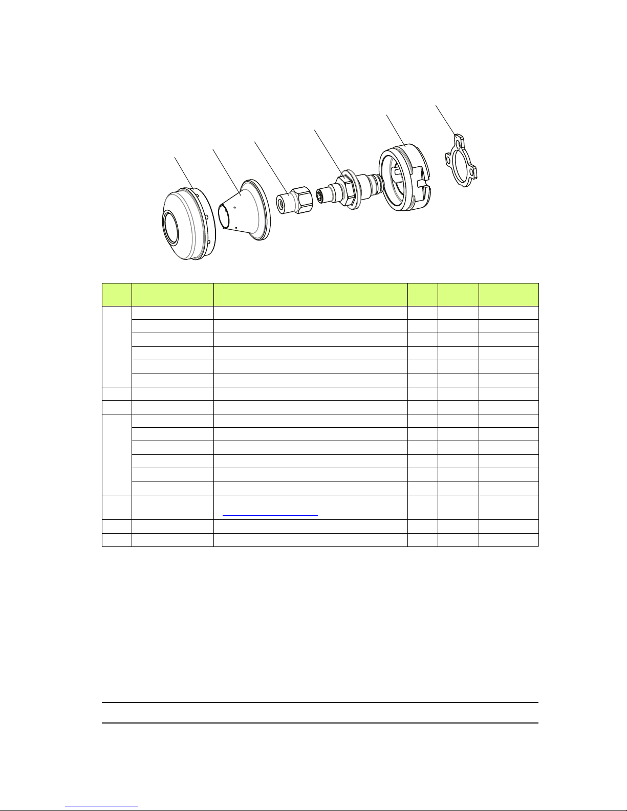
Index revision : A 63 7118
13.11. Hollow cone kit (not available for North American market)
(*)
Level 1: Standard preventive maintenance.
Level 2: Corrective maintenance.
Level 3: Exceptional maintenance.
Item
Part Number Description Qty
Sales
unit
Spare parts
level (*)
910025480-20 Hollow cone kit K20 1 1 3
910025480-30 Hollow cone kit K30 1 1 3
910025480-40 Hollow cone kit K40 1 1 3
910025480-50 Hollow cone kit K50 1 1 3
910025480-60 Hollow cone kit K60 1 1 3
910025480-70 Hollow cone kit K70 1 1 3
1 900011505 Cap 1 1 2
2 910018917 Spraying cone 1 1 2
3
910025472 Injector 20 hollow cone 1 1 1
910025473 Injector 30 hollow cone 1 1 1
910025474 Injector 40 hollow cone 1 1 1
910025475 Injector 50 hollow cone 1 1 1
910025476 Injector 60 hollow cone 1 1 1
910025477 Injector 70 hollow cone 1 1 1
4 910025478 Equipped hollow cone seat casing
(see § 13.11.1 page 64)
1 1 2
5 900011504 Hollow cone adaptator 1 1 3
6 900014821 Flat seal 1 1 1
DES06971
1
2
3
4
5
6

Index revision : A 64 7118
13.11.1. Equipped hollow cone seat casing
(*)
Level 1: Standard preventive maintenance.
Level 2: Corrective maintenance.
Level 3: Exceptional maintenance.
Rep Référence Description Qté
Unité
de
vente
Niveau
Pièces de
rechange
(*)
910025478 Porte siège cône creux équipé 1 1 2
1 999469300 Pastille carbure de répartition 1 1 1
2 900012300 Bague anti-extrusion 1 1 1
3 J3STKL075 Joint torique perfluoré 1 1 1
DES06972
1
2
3

Index revision : A 65 7118
13.11.2. Procedure for changing from a flat spray to a round spray
WARNING : To carry out this operation, th e gun must be disconnected from any supply (product
/ air / current).
Remove the flat spray:
1 Loosen the cap nut (Ref.: 910019358).
2 Remove the cap (Ref.: 130001435), if the injector does not come away at the same time,
remove it too
3 Loosen the seat casing (Ref.: 910019359) while pressing the trigger.
4 Remove the adaptor (Ref.: 910019360) and the flat seal (Ref.: 900014821) located at the
rear. Make sure you do not lose or break the high voltage contact and the O-ring
(Ref.:
J3STKL014).
5 Extract the first split ring (Ref.: 900010164) inside the cap nut and remove the cap.
Install the round spray (hollow cone):
1 Put the flat seal in place (Ref.: 900014821) and the hollow cone adaptor (Ref.: 900011504).
Make sure you do not lose or break the high voltage contact and the O-ring (Ref.:
J3STKL014).
2 Add a little dielectric grease to the HV contact and a film to the seat casing thread. Make
sure you do not lose the distribution pad carbide
(Ref.: 999469300) at the front of the part.
3 Screw the seat casing fu lly onto the barrel while pressing the trigger.
4 Add a film of dielectric grease to the threading at the front of the seat casing; make sure
you do not get any on the distribution carbide pad.
5 Screw the injector fully on the seat casing.
6 Insert the cap into the cap nut and put the retaining ring back in place.
7 Put the cone in place
8 Add a film of grease on the barrel threading
9 Tighten the cap nut fully (with its cap) on the barrel.

Index revision : A 66 7118
13.12. GNM 6080 control module
(*)
Level 1: Standard preventive maintenance.
Level 2: Corrective maintenance.
Level 3: Exceptional maintenance.
13.13. Options for the Nanogun Airmix® H2O guns
Online product filter
* Reduced filter dimension installed at the pump outlet for the LR versions, and the pump must
be equipped with a M 1/2 JIC output coupling.
Item
Part Number Description Qty
Sales
unit
Spare parts
level (*)
910017193 GNM 6080 CE control module 1 1 3
910017192
GNM 6080 CSA control module
(only USA and CANADA)
1 1 3
910005759 GNM 6080 fastening kit 1 1 3
842635 5-m mass cable, lug D: 6 1 1 3
Description Part Number Versions
Filter (M / F 1/2 JIC) 130000322 LR* 120 or 200 bar
Sieve 6 129609908 LR 120 or 200 bar

Index revision : A 67 7118
13.14. Appendices
13.14.1. Hose protection casing
This casing protects the hoses and cables, thereby guaranteeing flexibility and longevity.
13.14.2. Gun protective cover
13.14.3. Warning sign
13.14.4. Safety relief valve
Description Part number Sales unit
Rilsan hose protection
duct with 30 collars
910021086 50-m roll
Description Part Number Sales unit
Protective cover
900011711 10
Description Part Number Sales unit
Warning
sign
1407684 1
Description Part Number Sales unit
Safety relief valve
6.5 bar 1/4 G
903080401 1
DES01269
This sign must be hung in the booth.
Manual electrostatic equipment for the application of paint or varnish
• This equipment must only be used by SAMES trained personnel.
• The command module must be located at least 1,5m from the booth openings.
• The use of the command module must be completely dependent upon the running
of the booth's exhaust fan.
• Regroup the cables and pipes arriving to the spray gun to prevent them from
dragging on the ground where they could be severed.
• Only metallic recipients must be used for cleaning liquids. They must definitely be
grounded.
• Use cleaning liquids with a flash point higher than ambient temperature.
• Correctly ground all of the metallic parts in the booth, as well as the parts to be
painted.
• The operator and persons working nearby must wear antistatic shoes.
• The operator's hand must be in contact with the spray gun grip.
• Work on an antistatic floor such as bare concrete or a metallic grating.
• Switch off the command module for any maintenance operation, in particular for the
cleaning of the nozzle and the cap, and for the rinsing of the paint circuit with the
cleaning liquid.
• If the spray gun is equipped with a trigger lock, it must be engaged during the
cleaning of the nozzle and the cap and during a prolonged stop.
• The electrostatic application equipment must be maintained on a regular basis and
repaired according to the instructions in the manual.
WARNING
GB
WARNUNG
Elektrostatisches Handgerätzum Auftragen von Farben/Lacken von
• Dieses Gerät darf nur durch von SAMES ausgebildetem Personal bedient werden.
• Das Steuermodul ist mindestens 1,5 m von den Öffnungen der Kabine entfernt
anzubringen.
• Die Inbetriebnahme des Steuermoduls muss vom Betrieb des Ventilators des
Abzugs der Kabine abhängig sein.
• Zur Lackierpistole führende Kabel und Schläuche gruppieren, um zu vermeiden,
dass diese auf dem Boden liegen, wo sie beschädigt werden können.
• Für Reinigungsflüssigkeiten sind ausschliesslich Metallbehälter zu verwenden. Diese
müssen zuverlässig geerdet werden.
• Reinigungsflüssigkeiten mit einem Flammpunkt über der Raumtemperatur
verwenden.
• Alle Metallteile der Kabine sowie die zu beschichtenden Werkstücke sachgemäss
erden.
• Das Bedienungspersonal und Personal, das in unmittelbarer Nähe arbeitet haben
antistatisches Schuhwerk zu tragen.
• Die Hand des Bedieners muss direkten Kontakt zum Griff der Pistole haben.
Dieses Schild muss in der Kabine angebracht werden.
DE
WAARSCHUW
Elektrostatische handapparatuur voor appl
• Dit apparaat mag alleen door SAMES opgeleid person
• De bedieningsmodule moet zich op minder dan 1,5m
cabineopeningen bevinden.
• De inwerkingstelling van de bedieningsmodule moet o
inschakeling van de zuigventilator van de cabine.
• Groepeer de kabels en leidingen die bij het pistool uitk
grond slepen, waar ze kunnen worden afgesneden.
• Gebruik alleen metalen bakken voor de reinigingsvloe
wijze op de grond te worden gezet.
• Gebruik reinigingsvloeistoffen met een vlampunt dat h
omgevingstemperatuur.
• Zorg voor een degelijke aardaansluiting van alle metal
verfbare delen.
• De gebruiker en het personeel in zijn nabijheid dienen
dragen.
• De hand van de gebruiker heeft direct contact met de
Bevestig deze plaat in de ca
NL
ADVARSEL
Manuelt udstyr til elektrostatisk påføri
• Udstyret må kun anvendes af personale, der er uddan
• Betjeningsmodulet skal være anbragt mindst 1,5m fra
• Betjeningsmodulet må kun kunne tændes, når kabinen
gang.
• Alle kabler og slanger, der er forbundet til pistolen, bør
flyder på gulvet, hvor de risikerer at blive skåret over.
• Rengøringsvæskerne må kun opbevares i metalbehol
forbundet med jord.
• Der skal bruges rengøringsvæsker med et flammepun
• Alle metalliske dele i kabinen såvel som emnet, der sk
• Operatøren og de personer, der arbejder i nærheden,
• Operatørens hånd skal være i direkte berøring med pis
• Der skal arbejdes på et antistatisk underlag, såsom rå
• Betjeningsmodulet skal sættes ud af drift inden al vedl
rengøring af dysen eller hætten og rensning af malingsk
rengøringsvæsken.
• Hvis pistolen er udstyret med en anordning til aflåsning
være slået til under rengøringen af dysen eller hætten o
standsninger.
• Udstyret til elektrostatisk påføring skal vedligeholdes re
ifølge forskrifterne i brugsvejledningen.
Dette skilt skal være anbragt i
DK
VARNING
Manuell elektrostatisk utrustning för applikation av färg/lack
• Denna utrustning får endast användas av personal utbildad av SAMES.
• Manövermodulen skall vara belägen minst 1,5 m från hyttöppningana.
• Igångsättningen av modulen skall förutsätta inkoppling av hyttens utsugningsfläkt.
• Samla ihop kablar och slangar som går in på pistolen så att de inte ligger i vägen
på golvet, där de riskerar att skäras av.
• Endast metallbehållare får endast för rengöringsvätskor. De skall jordas på säkert
sätt.
• Använd rengöringsvätskor med en flampunkt som ligger över
omgivningstemperaturen.
• Jorda på korrekt sätt alla metalliska delar av hytten, liksom de delar som skall
målas.
• Operatören och personer som arbetar i närheten av de metalliska delarna skall
bära antistatiska skodon.
• Operatörens hand skall vara i direkt kontakt med pistolkolven.
• Arbeta på ett antistatiskt golv av typ bar betong eller en metallisk gallerdurk.
• Koppla bort manövermodulen vid varje underhållsarbete, i synnerhet vid rengöring
av munstycket, hatten och sköljningen av målningskretsen med rengöringsvätska.
• Om pistolen är utrustad med en avtryckarlåsning, skall denna vara ilagd vid
rengöringen av munstycket, hatten och vid ett långvarigt stopp.
• Den elektrostatiska applikationsutrustningen skall underhållas regelbundet och
repareras i enlighet med anvisningarna i användarmanualen.
Denna skylt skall placeras i hytten.
SE
VAROITUS
In Käsikäyttöiset sähköstaattiset maalaus-/lakkausruiskut
• Laitteita saa käyttää vain SAMESin kouluttama henkilöstö.
• Ohjausmoduuli on sijoitettava vähintään 1,5 m päähän maalauskopin aukoista.
• Ohjausmoduulin toiminta on kytkettävä maalauskopin imutuulettimen
käynnistymiseen.
• Katkeamisvaaran välttämiseksi maalausruiskun johdot ja letkut on sijoitettava siten,
että ne eivät laahaa maata.
• Puhdistusaineille käytettävä ainoastaan metallisäiliöitä. Säiliöiden maadoitus on
varmistettava.
• Käytettävä puhdistusaineita, joiden leimahduspiste on korkeampi kuin ympäristön
lämpötila.
• Kaikkien maalauskopin metalliosien sekä maalattavan kappaleen asianmukaisesta
maadoituksesta on huolehdittava.
• Laitteiston käyttäjän ja sen läheisyydessä työskentelevien on pidettävä antistaattisia
jalkineita.
• Käyttäjän käden on oltava suorassa kosketuksessa maalauspistoolin peräosan
kanssa.
Tämä kilpi on sijoitettava maalauskoppiin.
FI
 Loading...