


DOCUMENTATION
ELECTRONIC MIXING SYSTEM
CYCLOMIX
MICRO / MICRO+ / MICRO+ PH / MICRO+ PH+
Manual : 582.079.110-UK - 1902
Date: 07/02/19
Supersede : 23/05/16
Modif.:
TRANSLATION FROM THE ORIGINAL MANUAL
IMPORTANT : Before assembly and start-up, please read and clearly understand all the documents relating to
this equipment (professional use only).
THE PICTURES AND DRAWINGS ARE NON CONTRACTUAL. WE RESERVE THE RIGHT TO MAKE CHANGES WITHOUT PRIOR NOTICE..
SAMES KREMLIN SAS
l
13, chemin de Malacher
38 240 - MEYLAN - France
: 33 (0)4 76 41 60 60
www.sames-kremlin.com

578.034.130 1901
SAMES KREMLIN SAS
13, chemin de Malacher
38 240 - MEYLAN - France
: 33 (0)4 76 41 60 60
www.sames-kremlin.com
Pour une utilisation sure, Il est de votre responsabilité
de :
Lire attentivement tous les documents contenus
dans le CD joint avant la mise en service de
l’équipement,
D’installer, d’utiliser, d’entretenir et de réparer
l’équipement conformément aux préconisations de
SAMES KREMLIN ainsi qu’aux réglementations
nationales et/ou locales,
Vous assurez que les utilisateurs de cet équipement
ont été formés, ont parfaitement compris les règles de
sécurité et qu’ils les appliquent.
To ensure safe use of the machinery, it is your
responsibilityto:
Carefully read all documents contained on the
enclosed CD before putting the machinery into service,
Install, use, maintain and repair the machinery in
accordance with SAMES KREMLIN's recommendations
and national and/or local regulations,
Make sure that the users of the machinery have
received proper training and that they have perfectly
understood the safety rules and apply them.
Eine sichere Nutzung setzt voraus, dass Sie: :
alle in der CD enthaltenen Dokumente vor der
Inbetriebnahme der Anlage aufmerksam lesen,
die Anlage im Einklang mit den Empfehlungen von
SAMES KREMLIN sowie mit den nationalen und/oder
lokalen Bestimmungen installieren, verwenden,
warten und reparieren,
sich vergewissern, dass die Nutzer dieser Anlage
angemessen geschult wurden, die
Sicherheitsbestimmungen verstanden haben und sie
anwenden.
ES IT PT
FR UK DE
Para una utilización segura, será de su
responsabilidad:
leer atentamente todos los documentos que se
incluyen en el CD adjunto antes de la puesta en servicio
del equipo,
instalar, utilizar, efectuar el mantenimiento y reparar
el equipo con arreglo a las recomendaciones de
SAMES KREMLIN y a la normativa nacional y/o local,
cerciorarse de que los usuarios de este equipo han
recibido la formación necesaria, han entendido
perfectamente las normas de seguridad y las aplican.
Per un uso sicuro, vi invitiamo a:
leggere attentamente tutta la documentazione
contenuta nel CD allegato prima della messa in
funzione dell'apparecchio,
installare, utilizzare, mantenere e riparare
l'apparecchio rispettando le raccomandazioni di SAMES
KREMLIN, nonché le normative nazionali e/o locali,
accertarvi che gli utilizzatori dell'apparecchio
abbiano ricevuto adeguata formazione, abbiano
perfettamente compreso le regole di sicurezza e le
applichino.
Para uma utilização segura, é da sua
responsabilidade:
Ler atentamente todos os documentos incluídos no
CD em anexo antes de pör o equipamento em
funcionamento,
Proceder à instalação, utilização, manutenção e
reparação do equipamento de acordo com as
preconizações de SAMES KREMLIN, bem como com
outros regulamentos nacionais e/ou locais aplicáveis,
Assegurar-se que os utilizadores do equipamento
foram devidamente capacitados, compreenderam
perfeitamente e aplicam as devidas regras de
segurança.
NL SE FI
Voor een veilig gebruik dient u:
alle document op de bijgevoegde cd aandachtig te
lezen alvorens het apparaat in werking te stellen,
het apparaat te installeren, gebruiken, onderhouden
en repareren volgens de door SAMES KREMLIN
gegeven aanbevelingen en overeenkomstig de
nationale en/of plaatselijke reglementeringen,
zeker te stellen dat de gebruikers van dit apparaat
zijn opgeleid, de veiligheidsregels perfect hebben
begrepen en dat zij die ook toepassen.
För en säker användning av utrustningen ansvarar ni
för följande:
Läs noga samtliga dokument som finns på den
medföljande cd-skivaninnan utrustningen tas i drift.
Installera, använd, underhåll och reparera
utrustningen enligt anvisningarna från SAMES
KREMLIN och enligt nationella och/eller lokala
bestämmelser.
Försäkra er om att användare av denna utrustning
erhållit utbildning, till fullo förstått säkerhetsföreskrifterna
och tillämpar dem.
Käytön turvallisuuden varmistamiseksi
velvollisuutesi on:
Lukea huolella kaikki CD:llä olevat asiakirjat ennen
laitteiston käyttöönottoa,
Noudattaa laitteiston asennuksessa, käytössä,
kunnossapidossa ja huollossa SAMES KREMLIN in
suosituksia sekä kansallisia ja/tai paikallisia
määräyksiä,
Varmistaa, että laitteiston käyttäjät ovat koulutettuja
ja ymmärtävät täysin turvallisuusmääräykset ja miten
niitä sovelletaan.
PL CS SL
Dla zapewnienia bezpiecznego użytkowania na
użytkowniku spoczywa obowiązek:
Uważnego zapoznania się ze wszystkimi
dokumentami znajdującymi się na załączonej płycie CD
przed pierwszym uruchomieniem urządzenia,
Instalowania, użytkowania, konserwacji i naprawy
urządzenia zgodnie z zaleceniami firmy SAMES
KREMLIN oraz z przepisami miejscowymi,
Upewnienia, że wszyscy przeszkoleni użytkownicy
urządzenia zrozumieli zasady bezpieczeństwa i stosują
się do nich.
Pro bezpečné používání jste povinni:
Před uvedením zařízení do provozu si pozorně
přečíst veškeré dokumenty obsažené na přiloženém
CD,
Nainstalovat, používat, udržovat a opravovat
zařízení v souladu s pokyny firmy SAMES KREMLIN
a s národními a/nebo místními legislativními předpisy,
Ujistit se, že uživatelé tohoto zařízení byli vyškoleni,
že dokonale pochopili bezpečnostní pravidla a že je
dodržují.
Za varno uporabo ste dolžni:
natančno prebrati vse dokumente na CD pred
zagonom stroja,
inštalirati, uporabljati, vzdrževati in popravljati
opremo po določilih SAMES KREMLIN in v skladu z
veljavnimi nacionalnimi in/ali lokalnimi predpisi,
poskrbeti, da so uporabniki te opreme ustrezno
usposobljeni, poznajo varnostne predpise in da jih
upoštevajo.
SK HU RO
V záujme bezpečného je vašou povinnosťou:
pozorne si prečítať všetky dokumenty obsiahnuté na
priloženom CD predtým, ako zariadenie uvediete do
prevádzky,
nainštalovať, používať, udržiavať a opravovať
zariadenie v súlade s odporúčaniami spoločnosti
SAMES KREMLIN a národnými a/alebo miestnymi
predpismi,
uistiť sa, že používatelia tohto zariadenia boli
zaškolení, riadne porozumeli pravidlám bezpečnosti a
používajú ich.
Déclaration(s) de conformité au verso de ce document / Declaration(s) of conformity at the back of this document / Konformitätserklärung(en) auf der Rückseite dieser Unterlage
/ Declaración (es) de conformidad en el reverso de este documento / Dichiarazione/i di conformità sul retro del presente documento
/ Declaração(ções) de conformidade no verso do documento / Conformiteitsverklaring(en) op de keerzijde van dit document / Försäkran om överensstämmelse på omstående sida
av detta dokument / Vaatimustenmukaisuusvakuutukset tämän asiakirjan kääntöpuolella / Deklaracja(e) zgodności na odwrocie dokumentu
/ Prohlášení o shodě se nachází/nacházejí na zadní straně tohoto dokumentu / Deklaracija(e) o skladnosti na hrbtni strani tega dokumenta / Vyhlásenie/-a o zhode sa nachádzajú na
zadnej strane dokumentu / A dokumentum hátlapján szereplő megfelelőségi nyilatkoz(ok) / Declaraţii de conformitate pe versoul acestui document
A biztonságos használat érdekében az Ön
felelőssége, hogy:
a berendezés üzembe helyezése előtt figyelmesen
elolvassa a mellékelt CD által tartalmazott összes
dokumentumot,
a berendezést a SAMES KREMLIN ajánlasainak
valamint a nemzeti és/vagy helyi szabályozásoknak
megfelelően helyezze üzembe, használja, tartsa karban
és javítsa,
megbizonyosodjon róla, hogy a berendezés
felhasználói képzettek, tökéletesen megértették és
alkalmazzák a biztonsági előírásokat.
Pentru o utilizare sigură, este responsabilitatea dvs.
să:
Citiţi cu atenţie toate documentele de pe CD-ul
anexat, înainte de punerea în funcţiune a
echipamentului,
Instalaţi, utilizaţi, întreţineţi şi reparaţi echipamentul
conform instrucţiunilor SAMES KREMLIN precum şi
reglementărilor naţionale şi/sau locale,
Vă asiguraţi că utilizatorii acestui echipament au
fost instruiţi, au înţeles perfect regulile de securitate şi
le aplică integral.
SAMES KREMLIN N° : 578.034.130-1901

DECLARATION UE DE CONFORMITE
EU DECLARATION OF CONFORMITY
EU- KONFORMITÄTSERKLÄRUNG
DECLARACIÓN UE DE CONFORMIDAD
DICHIARAZIONE DI CONFORMITÀ UE
DECLARAÇÃO UE DE CONFORMIDADE
EU-CONFORMITEITSVERKLARING
EU-FÖRSÄKRAN OM ÖVERENSSTÄMMELSE
EU- VAATIMUKSENMUKAISUUSVAKUUTUS
DEKLARACJA ZGODNOŚCI UE
EU PROHLÁŠENÍ O SHODĚ
IZJAVA EU O SKLADNOSTI
VYHLÁSENIE O ZHODE
EU-MEGFELELŐSÉGI NYILATKOZAT
DECLARAŢIA DE CONFORMITATE UE
Le fabricant / The manufacturer / Der Hersteller
/ El fabricante / Il produttore / O fabricante
/ De fabrikant / Tillverkare / Valmistaja / Producent / Výrobce
/ Proizvajalec / Výrobca / Gyártó / Fabricantul:
Déclare que le matériel désigné ci-après / Herewith declares that the equipment / erklärt hiermit, dass die / Declara que el material designado a
continuación / Dichiara che il materiale sottoindicato / Declara que o material a seguir designado / verklaart dat de hieronder aangeduide apparatuur
/ Kungör att den utrustning som anges här nedan / ilmoittaa, että alla mainitut laitteistot / Oświadcza, że wymienione poniżej urządzenia / Prohlašuje,
že níže uvedené vybavení / Izjavlja, da je opisana oprema spodaj / Vyhlasuje, že zariadenie uvedené nižšie / Kijelenti, hogy a megjelölt anyag a
továbbiakban / Declară că echipamentul precizat mai jos:
SAMES KREMLIN SAS
13, chemin de Malacher
38 240 - MEYLAN - FRANCE
Tél. : 33 (0)4 76 41 60 60
SYSTEME DE DOSAGE ELECTRONIQUE / MIXING & DOSING SYSTEM
ELEKTRONISCHE 2-K- ANLAGE / SISTEMA DE DOSIFICACIÓN ELECTRÓNICA
CYCLOMIXTMMICRO
CYCLOMIXTMMICRO+
CYCLOMIXTMMICRO+ PH
CYCLOMIXTMMICRO+ PH+
Est conforme à la législation d’harmonisation de l’Union applicable suivante / Is in conformity with the relevant Union harmonisation legislation / Erfüllt
die einschlägigen Harmonisierungsrechtsvorschriften der Union / es conforme con la legislación de armonización pertinente de la Unión / è conforme
alla pertinente normativa di armonizzazione dell’Unione / in overeenstemming met de desbetteffende harmonisatiewetgeving van de Unie / med den
relevanta harmoniserade unionslagstiftningen / on asiaa koskevan unionin yhdenmukaistamislainsäädännön vaatimusten mukainen / jest zgodny z
odnośnymi wymaganiami unijnego prawodawstwa harmonizacyjnego / Shoduje se s následující příslušnou evropskou harmonizační legislativou
/ V skladu s harmonizirano zakonodajo Unije / Je v súlade s uplatniteľnými harmonizačnými právnymi predpismi EÚ / Megfelel a következő
alkalmazandó uniós harmonizációs szabályozásnak / Este conform cu legislaţia aplicabilă de armonizare de mai jos
Directive Basse Tension / Low Voltage Directive / Niederspannung-Richtlinie / Directiva Baja Tensión / Direttiva Bassa
Tensione / Directiva de Baixa Tensão / Richtlijn Laagspanning / Lågspänningsdirektivet / Pienjännitedirektiivi / Dyrektywa
Niskonapięciowa / Směrnice Pro Nízké Napĕtí / Direktiva O Nizki Napetosti / Smernica O Nízkom Napätí / Feszültséghatárra
Vonatkozó Irányelv / Directiva Privind Tensiunile Joase
Directive Compatibilité Electromagnétique / Electromagnetic Compatibility Directive / Richtlinie Für Elektromagnetische
Verträglchkeit / Directiva de Compatibilidad Eletromagnética / Direttiva Compatibilita Elettromagnetica / Directiva relativa à
Compatibilidade Eletromagnética / Richtlijn Elektromagnetische Compatibiliteit / Direktivet om Eletktromagnetisk Kompatibilitet
/ EMC-direktivi / Dyrektywa Kompatybilności Elektromagnetycznej / Směrnice Pro Elektromagnetickou Kompatibilitu
/ Direktiva O Elektromagnetni Združljivost / Smernica O Elektromagnetickej Kompatibilite / Az Elektromágneses
Összeférhetőségre vonatkozó Irányelv / Directiva Privind Compatibilitatea Electromagnetică
2014/35/UE
2014/30/UE
SAMES KREMLIN - 2 - N° : 578.034.130-1901

La présente déclaration de conformité est établie sous la seule responsabilité du fabricant / This declaration of conformity is issued under the sole
responsibility of the manufacturer / Die alleinige Verantwortung für die Ausstellung dieser Konformitätserklärung trägt der Hersteller / La presente
declaración de conformidad se expide bajo la exclusiva responsabilidad del fabricante / La presente dichiarazione di conformità è rilasciata sotto la
responsabilità esclusiva del fabbricante / A presente declaração de conformidade é emitida sob a exclusiva responsabilidade do fabricante / Deze
conformiteitsverklaring wordt verstrekt onder volledige verantwoordelijkheid van de fabrikant / Denna försäkran om överensstämmelse utfärdas på
tillverkarens eget ansvar / Tämä vaatimustenmukaisuusvakuutus on annettu valmistajan yksinomaisella vastuulla / Niniejsza deklaracja zgodności
wydana zostaje na wyłączną odpowiedzianość producenta / Toto prohláŝení o skodě se vydává na výhradní odpovědnost výrobce / Za izdajo te izjave
o skladnosti je odgovoren izključno proizvajalec / Toto vyhlásenie o zhode sa vydáva / na vlastnú zodpovednosť výrobcu / Ezt a megfelelőségi
nylatkozatot a gyártó kizárólagos felelőssége mellett adják ti / Prezenta declaraţie de conformitate este emisă pe răspunderea exclusivă a
producătorului.
Hervé WALTER
Directeur Recherche & Développement / Research & Development Director / Direktor für Forschung & Entwicklung
/ Director de Investigación y Desarrollo / Direttore Ricerca e sviluppo / Diretor de Pesquisa e desenvolvimento/
Manager Onderzoek en Ontwikkeling / Direktör för Forskning och Utveckling / Johtaja tutkimus ja kehitys / Dyrektor
ds. Badań i rozwoju / Ředitel výzkumu a vývoje / Direktor za raziskave in razvoj / Riaditeľ pre výskum a vývoj /
Kutatási és Fejlesztési Igazgató / Director de cercetare și dezvoltare
Fait à Meylan, le / Established in Meylan, on / Geschehen zu Meylan, am / En Meylan, a / Redatto a Meylan, / Vastgesteld te Meylan, / Utformat i
Meylan, den / Meylan, Ranska, / Sporządzono w Meylan, dnia / Meylan, dnia / V Meylanu, / V Meylan dňa / Kelt Meylanban, / Întocmită la Meylan, pe
data de 25/01/2019 - 01/25/2019
SAMES KREMLIN - 3 - N° : 578.034.130-1901

INSTRUCTION MANUAL
CYCLOMIX
TM
MICRO, MICRO+
MICRO+ PH,
MICRO+ PH+
MIXING SYSTEM
# 155.660.9XX
Manual : 1812 573.191.112
Date : 05/12/18 - Cancels : 15/12/14
Modif.: Update
TRANSLATION FROM THE ORIGINAL MANUAL
IMPORTANT : Before assembly and start-up, please read and clearly understand all the documents
relating to this equipment (professional use only).
THE PICTURES AND DRAWINGS ARE NON CONTRACTUAL. WE RESERVE THE RIGHT TO MAKE CHANGES WITHOUT PRIOR
NOTICE.
SAMES KREMLIN SAS
l
13, chemin de Malacher
38 240 - MEYLAN - France
: 33 (0)4 76 41 60 60
www.sames-kremlin.com

INSTRUCTION MANUAL
CYCLOMIX
TM
MICRO, MICRO+, MICRO+ PH, MICRO+ PH+
MIXING SYSTEM
TABLE OF CONTENTS
1. GENERAL SAFETY INSTRUCTIONS ......................................................................................................... 3
INSTALLATION REQUIREMENTS ............................................................................................ 3
EQUIPMENT REQUIREMENTS ................................................................................................ 3
MAINTENANCE REQUIREMENTS ............................................................................................ 4
ENVIRONMENT ......................................................................................................................... 4
2. DESCRIPTION ............................................................................................................................................. 5
3. OPERATING PRINCIPLE ............................................................................................................................ 7
4. TECHNICAL FEATURES ............................................................................................................................ 8
5. INSTALLATION ........................................................................................................................................... 9
DESCRIPTION OF THE LABEL MARKINGS ............................................................................ 9
INSTALLATION DIAGRAM ...................................................................................................... 11
IMPLANTATION ....................................................................................................................... 12
CONNECTION OF THE CONTROL UNIT AND OF THE FLUID PA RT .................................. 14
6. OPERATING .............................................................................................................................................. 15
DRIVING FROM THE CYCLOMIXTM MICRO ........................................................................... 15
SWITCHING ON THE CYCLOMIXTM MICRO .......................................................................... 15
7. FIRST SWITCHING ON ............................................................................................................................. 16
8. FIRST PLACING INTO OPERATION ........................................................................................................ 18
FLUSHING OF THE PUMPS AND OF THE CYCLOMIXTM MICRO INTO SOLVENT ............. 18
START-UP OF THE CYCLOMIXTM MICRO ............................................................................. 18
9. APPLICATION PROGRAMMING (F3) ...................................................................................................... 19
PASSWORD ............................................................................................................................. 19
PROCEDURE TO GET THE VERSION NUMBER OF THE ELECTRONIC CARD ................ 19
PARAMETERS FOR CYCLOMIXTM MICRO WITHOUT CATALYST FLUSHING ................... 20
PARAMETERS FOR CYCLOMIXTM MICRO WITH CATALYST FLUSHING ........................... 21
10. PRODUCTION (F1) .................................................................................................................................... 23
PROPORTIONING TEST ......................................................................................................... 24
11. FLUSHING (F2) .......................................................................................................................................... 24
12. CONSUMPTIONS / PRINT (F4) ................................................................................................................. 26
13. DOWNLOADING DATA FROM CYCLOMIX MICRO TO A COMPUTER ................................................. 27
14. INDICATIONS GIVEN BY THE LEDS ........................................................................................................ 31
15. MAINTENANCE ......................................................................................................................................... 31
TROUBLESHOOTING .............................................................................................................. 33
DIAGNOSTICS ......................................................................................................................... 34
16. DISASSEMBLY - REASSEMBLY ............................................................................................................. 36
MIXER ....................................................................................................................................... 36
FLOWMETER ........................................................................................................................... 36
NEW MODULE INSTALLATION (OR MODULE REPLACEMENT) ........................................ 37
PILOTED VALVES (FLUID VALVES AND TEST VALVES) ..................................................... 38
SAMES KREMLIN Page 1 Manual : 573.191.112

ADDITIONAL DOCUMENTATIONS :
Declaration
EU declaration of conformity Doc. 578.034.130
Annexes
Mixing ratio chart Doc. 573.191.120
Pneumatic & electric diagrams 055.660.999
Spare parts
CyclomixTM micro Doc. 573.359.050
Color changer Doc. 573.186.112 + 573.187.050 + 573.188.050
CyclomixTM : Flowmeters and sensors
replacement
Doc. 573.705.070
SAMES KREMLIN Page 2 Manual : 573.191.112

Dear Customer, You are the owner of our new CYCLOMIXTM MICRO mixing system and we would
like to take this opportunity to thank you.
To make sure your investment will provide full satisfaction, special care has been taken by SAMES
KREMLIN during all designing and manufacturing processes. To obtain the best result, safe and
efficient operation of your equipment, we advice you to read and make yourself familiar with this
instruction and service manual.
1. GENERAL SAFETY INSTRUCTIONS
The CYCLOMIXTM MICRO mixing system shall be installed outsid e the exp losive
area. It shall be installed in a safe area (non-explosive area according to the ATEX
directive - refer to § 5).
The display control unit must not be installed above the fluid module.
WARNING : Any misuse of the equipment or accessories can damage them, result in serious body
injury, fire or explosion hazard and reduce the equipment working life. Read carefully the safety
instructions hereafter.
The personnel involved in operating and servicing this equipment must be aware of all safety
requirements stated in this manual. The workshop supervisor must be certain that the personnel has
perfectly understood the safety instructions and complies with them.
Read all instruction manuals as well as the tags of the equipments before operating the equipment.
Read local safety instructions and comply with them.
INSTALLATION REQUIREMENTS
Ground the equipments.
Use the equipment only in a well-ventilated area to prevent from serious body injuries, fire and
explosion hazards. Do not smoke in the spray area.
Never stock paints and solvents in the spray area. Always close the pots and the tins.
Keep the spray area clean and free from debris (solvent, rags,…).
Read paint and solvent manufacturer's technical instructions.
Spraying of some materials may result in hazardous working conditions. To protect the operator,
respirator mask, hand cream and glasses are required (Refer to chapter "Safety equipment" of
SAMES KREMLIN selection guide).
EQUIPMENT REQUIREMENTS
The operating pressure of these equipments is particularly high. Consequently, some precautions
must be taken in order to prevent from accidents and from unsafe working conditions.
Never exceed the components maximum working pressure of the equipment.
HOSES
Do not use hoses with a maximum burst-proof pressure less than four times the maximum service
pressure of the pump (see data sheet).
Be certain hoses are not crimped, leaking and not unrolled.
Be certain hoses are in good conditions and showing no evidence of damage.
Use only air hose with static conductor to connect the pump with the spray gun.
All fittings must be tight and in good condition.
PUMP
Ground the equipment (use the connection on the pump).
Do not use any product or solvent incompatible with the pump components.
Use the appropriate solvent for the material being sprayed to increase the equipment working life.
SAMES KREMLIN Page 3 Manual : 573.191.112

GUN
Never wipe the end of the tip with the fingers.
Always depressurize air and fluid hoses before carrying out any servicing on the gun.
Never point the spray gun at anyone or at any part of the body.
CYCLOMIXTM MICRO
Do not install the CYCLOMIX
TM
MICRO in an explosive area. It shall be in a safe area (non
explosive area).
The display control unit must not be installed above the fluid module.
Connect the display control unit to the mains supply fitted with a ground.
The fluid module is fitted with a ground. Connect the ground cable to earth.
Do not use any product or solvent incompatible with the components of the CYCLOMIX
TM
MICRO.
Use the appropriate solvent for the material being sprayed to increase the equipment
working life.
Wear protective glasses to protect the operator from possible discharges during the
handling of the CYCLOMIX
TM
MICRO test valves.
Do not use electrostatic spraying for water-based paints with a resistivity lower than 5 M
Ω
.
MAINTENANCE REQUIREMENTS
Guards (air motor cover, coupling shields, connectors,…) have been designed for
safe use of the equipment.
The manufacturer will not be held responsible for bodily injury or failure and / or
damage to property due to removal or partial removal of the guards.
Never modify these equipments.
Check them daily, keep them in a good condition and replace the worn parts only with SAMES
KREMLIN parts.
Before cleaning or removing components of the equipment, it is compulsory :
1 - to stop the air supply,
2 - to open the gun fluid circuit to depressurize the hoses,
3 - to shut off the CYCLOMIXTM MICRO electrical supply,
4 - to open the drain valves.
ENVIRONMENT
The equipment consists of a label plate with the name of the manufacturer, the
equipment part number, the interesting informations to use correctly the
equipment (pressure, voltage…) and the above pictogram.
The equipment is designed with and consists of high quality materials and
components which can be re-used.
The 2012/19/UE European Directive covers all equipments with a crossed-out
bin pictogram. Please inform yourself about the collection systems for electric
and electronic equipments.
Please act according to local rules and do not throw the old equipments with
household wastes. A correct disposal of the old equipment will help prevent
negative consequences for the environment and health.
SAMES KREMLIN Page 4 Manual : 573.191.112

2. DESCRIPTION
The CYCLOMIXTM MICRO mixing system is designed for applying two-component paints and varnishes
(water-based or solvanted).
It is available for 2 technologies of application : pneumatic spraying, AIRMIX spraying
(maximum pressure : 172 bar / 2500 psi).
It comes in an independent form. It is only supplied with compressed air (maximum 6 bar / 87 psi) and a
mains supply (115V / 230V).
It consists of :
- a control unit (2) with automaton and electromagnetic control components,
- a fluid module (1) that receives the volumetric meters, the automatic valves for materials and solvents
and electropneumatic control components.
Captions :
1 Fluid module 7 Electrovalves
2 Control unit 8 Air flow switch
3 Display unit 9 Color changer
9a : base CTM
9b : cata CTM
4 Flowmeters 10 Protective housing
5 Automatic valve 11 Three-way valve
6 Mixer 12 Non-return valve
1 8 7 6 2
3
10
5
11
9b
12
9a
4
Material
outlet
Material
inlet
SAMES KREMLIN Page 5 Manual : 573.191.112

CONTROL UNIT FRONT PART
Ind. Description Function
- Red LED Fault
- Orange LED Operating (except producti on)
- Green LED Production
The CYCLOMIXTM MICRO is totally programmable via a man/machine interface. The screen indicates
continuously by a simple identification, the statuses of the CYCLOMIX
TM
MICRO and enables to have
access to the essential functionalities: ON / OFF - FLUSHING -PRODUCTION.
The informations relating to the operating of the CYCLOMIX
TM
MICRO (real-time display of the ratio, of
the consumption…) can be read on the LCD screen.
The CYCLOMIX
TM
MICRO saves continuously the instantaneous consumptions of base, catalyst and
solvent as well as the total consumptions and the emissions of Volatile Organic Compounds (VOC)
during the operating of the equipment.
On the control unit, there is a cord grip. It enables to supply electricity to the CYCLOMIX
TM
MICRO via a
safety isolating switch (115V / 230V).
Do not use electrostatic spraying for water-
based paints or paints with a
resistivity lower than 5 MΩ.
SAMES KREMLIN Page 6 Manual : 573.191.112

3. OPERATING PRINCIPLE
The 2 BASE and CATALYST materials are sent to the mixing system from 2 pumps or pressure tanks.
The base crosses a piloted valve (A1) and a meter (CA), the catalyst is directly sent to the meter (CB).
The cycle begins with the opening of the BASE valve (A1). The 2 meters send their informations to the
computer that shuts off the catalyst valve (VP6) when the computerized mixing ratio is reached.
The mixing process is based on a base constant flow. The catalyst flow is injected low under high
frequency. The injection is made directly into the base flux at the mixer level.
The automaton checks continuously the mixing ratio and if it notices a fault that it cannot correct, an
alarm is activated. The CYCLOMIX
TM
MICRO goes on safety mode.
TA
vp6
A1
SA
CB
CA
AR2
AR1
IN
A SA
MEL
A2
A3
A
A
B1
SB
B SB
A1 Base piloted valve (A) IN Three way-valve to mixer
SA Base solvent piloted valve(SA) TA Sampling outlet for the base
A2 Base piloted valve (depending upon version) CA Base meter
A3 Base piloted valve (depending upon version) CB Cata meter
B Catalyst piloted valve (depending upon
version)
VP6 Injection piloted valve
SB Cata solvent piloted valve (depending upon
version)
MEL Mixer
SAMES KREMLIN Page 7 Manual : 573.191.112

4. TECHNICAL FEATURES
Number of colors : 1 or 3
Number of catalyst : 1
Solvent paints compatibility
Piloting via magnet on the control bay
Print kit (connection to a printer)
Voltage : 230V / 115V - 10W
Air pressure :
minimum 4 bar / 58 psi; maximum 6 bar / 87 psi
Fluid pressure: from 2 to 175 bar / from 29 to 2538 psi
Weight : 25 kg / 55 lb
Dimensions :
- control unit : 370 mm x 172.5 mm x 110 mm
/ 14.6" x 6.8" x 4.3"
- fluid module : 370 mm x 460 mm x 110 mm
/ 14.6" x 18.1" x 4.3"
Fluid circuits (base and cata) made of stainless steel for
the CyclomixTM Micro and Micro+.
CATALYST circuit made of 316 L stainless steel Circuit
for the Cyclomix
TM
Micro+ PH.
Adjustable mixing ratio : 1/0 and from 0,6/1 to 20/1
(BASE volume / CATALYST volume) (0% and from 166%
to 5%)
Measure precision : 1 %
Mixed fluid flow : from 100 to 2000 cm3/mn
Solvent flow : 7000 cm3/mn
Fluid viscosity : from 30 to 5000 cps
Mixing permanent check
Adjustable threshold alarm
Adjustable pot-life indicator
Automatic mixing control cycle
Automatic flushing cycle (time)
VOC display
Total indicator for base, catalyst and solvent
consumption
OPTION :
*Auto-wash (gun support)
You cannot go to production with the auto-
wash, no
connection to the CYCLOMIXTM MICRO.
* Connecting cable (5 m).
* Pickit 2 (Electronic programming kit) : the kit allows you
to update the program on the electronic cards.
Connections :
- Air :
Inlet : F 1/4 BSP / Outlet : F 1/4 BSP
- Material : :
Inlet : M 1/2 JIC / Outlet : M 1/2 JIC
SAMES KREMLIN Page 8 Manual : 573.191.112

NOTA : The version 2.82 is only compatible on electronic boards with version higher than V.2.32. Here
after an overview of major versions :
Kinf of
processor
- Electronic
card
Manufacturing
date first units
Soft
version
Presence of error 6 Soft compatibility
with 2.82 latest
version
PIC 18F4520
-
2.31 - -
PIC 18F4620
09 Y 1001
2.32 - Yes
10 Y 1133
2.6
Yes
Yes
14 Y 1152
2.82
Yes
- Can be setup with P12
Yes
Different versions of the CYCLOMIXTM MICRO :
Configurations
BASE
CATALYST
CYCLOMIXTM MICRO
1 base + 1 solvent
1 cata
3 bases + 1 solvent
1 cata
CYCLOMIXTM MICRO +
1 base + 1 solvent 1 cata + 1 solvent
3 bases + 1 solvent 1 cata + 1 solvent
CYCLOMIXTM MICRO+ PH
1 base + 1 solvent 1 cata + 1 solvent
3 bases + 1 solvent 1 cata + 1 solvent
The control unit is the same for all the versions of the CYCLOMIXTM MICRO.
You can change the configuration displacing the shunt located on the µ card (J7 terminal)
- (refer to"Annexes" - electric diagram).
5. INSTALLATION
DESCRIPTION OF THE LABEL MARKINGS
The CYCLOMIXTM MICRO is fitted with 2 label markings : a label marking on the control unit and the other one
on the fluid module.
Marking label on the control unit
(bay located outside the spray booth in a safe area)
Marking label on the fluid module
(fluid module located outside the spray booth in a
safe area)
SAMES KREMLIN Page 9 Manual : 573.191.112

CONTROL UNIT :
SAMES KREMLIN
STAINS FRANCE
Name and address of the manufacturer
CE
European conformity
Tension
CYCLOMIXTM MICRO voltage
P air
Maximum air pressure
P prod
Maximum fluid pressure
Serie / Serial
Number given by SAMES KREMLIN. The two first numbers indicate the
manufacturing year.
Ref
CYCLOMIXTM MICRO part number
Phase
Single phase
Fréquence
50-60Hz / Mains frequency
Ampérage
Maximum current used
NE PAS DEBRANCHER
SOUS TENSION
DO NOT DISCONNECT
WHILE POWER ON
-
Environmental Indication
(refer to § 2 - Environment)
FLUID MODULE :
SAMES KREMLIN
STAINS FRANCE
Name and address of the manufacturer
CE
European conformity
P air : 6 bar / 87 psi
Maximum air pressure
P prod : 175 bar / 2536 psi
Maximum fluid pressure
NE PAS DEBRANCHER
SOUS TENSION
DO NOT DISCONNECT
WHILE POWER ON
-
Environmental Indication
(refer to § 2 - Environment)
Caution!
The CYCLOMIX
TM
MICRO mixing system must be installed outside the explosive area.
It must be installed in a safe area (non explosive area according to the ATEX directive).
The control unit must not be above the fluid module.
The control unit must be connected to a mains supply fitted with a ground.
The ground of the fluid module must be grounded.
SAMES KREMLIN Page 10 Manual : 573.191.112

INSTALLATION DIAGRAM
A ATEX zone
B Non explosive area (safe area)
C ATEX zone
1A CYCLOMIXTM MICRO control unit
1B CYCLOMIXTM MICRO fluid module
2 Pumps + Accessories
The user is liable for the delimitation of the zones which depends on the materials
used, the material environment and the use conditions (refer to EN 60079 -10
standard).
SAMES KREMLIN Page 11 Manual : 573.191.112

IMPLANTATION
There are different ways to install the CYCLOMIXTM MICRO to answer to the majority of installations.
Nevertheless, some installations are forbidden because dangerous.
The control unit must not be installed the fluid module.
Fixing the control unit on the fluid module is forbidden.
Correct installation :
the control unit is not fixed to the fluid module.
Incorrect installation :
the control unit is fixed to the fluid module.
Correct installation :
The display unit and the fluid module are installed in a safe area.
Incorrect installation :
the display unit and/or the fluid module are installed in the spraybooth.
SAMES KREMLIN Page 12 Manual : 573.191.112

Assembly for piloting outside the booth :
The CYCLOMIXTM MICRO gets two parts to
enable the mismatch of the control part (5 m
/ 196.85 ft cable between the 2 components).
Assembly for piloting in the booth :
There is a control kit in booth (available in
option).
That kit enables to fix the control box on the
spray booth by means of a glass sheet and
to pilot that one inside. The piloting is
carried out thanks to a magnet provided with
the CYCLOMIX
TM
MICRO. The distance
between the control box and the fluid part is
of 5 m / 196.85 ft (cable provided with the
CYCLOMIX
TM
MICRO).
SAMES KREMLIN Page 13 Manual : 573.191.112

CONNECTION OF THE CONTROL UNIT AND OF THE FLUID PART
The CYCLOMIX
TM
MICRO must be
connected to a dry and clean
compressed air (minimum 4 bar / 58 psi)
and to a single phase electric supply
(115 V / 230V) connected to an isolating
switch. The network ground will be
connected in the control bay on a contact
provided.
Before connecting the
CYCLOMIX
TM
MICRO, be certain the
mains voltage is the
same than the
one of the CYCLOMIXTM MICRO
(230
V).
If no, open the electric box removing the
protective housing (10) and shift the
staple (230V 115V).
The air connection of the CYCLOMIX
TM
MICRO
is Female 1/4 G (air inlet = R1
and air outlet = R2).
The connection between the control unit
and the fluid module is carried out via
the
provided cable, length 5 m / 196.85 ft
.
For lengths up to 5 m / 196.85 ft
connect
the cables between them (male-female).
The connection between the two
cables must not be in the explosive area.
A valve fitted with fittings is supplied with
the CYCLOMIXTM MICRO
. It will be
mounted on the gun air inlet : it enables
to shut off quickly the fan air (priming,
flushing stage).
Fuse 160 mA
for CYCLOMIX
TM
MICRO
with serial number < to 09Y1080
Fuse 315 Ma
for CYCLOMIX
TM
MICRO
with serial number >to 09Y1080
Connection of the fluid inlets :
The fluid inlets are M 1/2 JIC.
We advice you to install AIRMIX
filters on the fluid inlets (catalyst and
base).
The base(s) and the base solvent are
connected on the color changer installed
on the CYCLOMIXTM MICRO.
The catalyst is connected :
-
directly on the elbow installed before
the non-return valve,
-
or on the color changer (cata and cata
solvent) installed in the CYCLOMIX
TM
MICRO.
It depends upon the configuration of the
CYCLOMIXTM MICRO.
The air connection is made on the two
G 1/4 connecting parts.
Air inlet /
outlet
Base(s) and solvent base
Catalyst
SAMES KREMLIN Page 14 Manual : 573.191.112

Assemble filters at the outlet of the BASE and CAT A p u mps.
Assemble pressure regulators at the outlet of the BASE and CATA pumps.
Install the fluid and air hoses between the pumps and the CYCLOMIXTM MICRO, and between the
CYCLOMIX
TM
MICRO and the gun. When choosing the fluid hoses, comply with the pressures delivered
by the pumps. For the air hoses, install non-static hoses.
Unscrew the regulators before supplying air to the installation.
Check that the three way-valve is in the IN fluid circuit sense and not in the TA circuit sense.
Nota : To connect the SOLVENT pump (CATA) to the CYCLOMIX MICRO :
- choose a CYCLOMIX
TM
MICRO set up with 1 catalyst and one cata solvent,
- or disconnect the CATA hose at non-return valve level (CATA) of the equipment and replace it
connecting the SOLVENT hose (CATA).
6. OPERATING
DRIVING FROM THE CYCLOMIX
TM
MICRO
SCREEN
The different menus and the informations relating to the CYCLOMIXTM MICRO are displayed on the
alphanumeric screen.
KEYBOARD
ESC
That key enables to quit the menus or the different modes (production, flushing,
parameters).
↵
That key enables to enter in the different menus or to validate a value of parameter.
▲
That key enables to shift from a menu to another and to increase the value of a
parameter during modifications of value.
▼
That key enables to shift from a menu to another and to decrease the value of a
parameter during modifications of value.
The keyboard is used thanks to a magnet provided with the CYCLOMIXTM MICRO. That piloting mode
enables to drive the CYCLOMIX
TM
MICRO inside the booth if the box is installed behind the booth glass.
That technology enables the operator to save time and to carry out his work from the application place.
SWITCHING ON THE CYCLOMIX
TM
MICRO
The placing of the system into operation requires that the BASE, CATALYST and
SOLVENT drums are full enough to ensure the production.
Connect the gun before placing the system into operation.
Supply air to the CYCLOMIXTM MICRO (minimum 4 bar / 58 psi).
Supply air to the air regulators of the pumps (BASE, CATALYST, SOLVENT).
Switch on the control unit (switch located on the side of the unit).
When switching on the control unit, a menu is displayed on the screen.
Nota : Parameters have been programmed in the factory before the delivery of the CYCLOMIX
TM
MICRO.
You must adapt the parameters to the use. They must be modified by an authorized person (refer to list
of parameters).
SAMES KREMLIN Page 15 Manual : 573.191.112

7. FIRST SWITCHING ON
STANDARD MENU
When switching on, the CYCLOMIX
TM
MICRO is waiting. The 'F-1' menu corresponds to the shift to the
production mode. There are 4 different menus : they enable to control the CYCLOMIX
TM
MICRO.
- F-1 : production
- F-2 : flushing
- F-3 : parameters
- F-4 : consumptions
To surf from a menu to another, you must move placing the magnet on the sensors indicated with '▲/▼'.
The menus scroll as follows :
Countdown of the fluid life time.
(countdown from 9 to 0; 9 represents
90% of the remaining time before the
regeneration).
A line is visible when the CYCLOMIX
TM
MICRO is flushed.
Function 1
Color 1
Consumptions
Production
Flushing
Parameters
SAMES KREMLIN Page 16 Manual : 573.191.112

Arborescence of the menus
Menu pending choice of
program
Menu of program change
ESC
ESC/↵
ESC/↵
ESC/↵
ESC/↵
ESC/↵
↵
ESC
3 color's
CYCLOMIXTM MICRO
↵
ESC
↵
ESC
With CATA flushing
Without CATA
flushing
If CATA flushing
↵
ESC
SAMES KREMLIN Page 17 Manual : 573.191.112

8. FIRST PLACING INTO OPERATION
During that first placing into operation, it is compulsory to have all the pumps
into solvent as well as the CYCLOMIX
TM
MICRO to ensure the good quality of
the fluid get by the CYCLOMIX
TM
MICRO.
The fluid pressure must not exceed 20 bar / 290 psi.
We advice you to install the TB fitting (provided with the CYCLOMIX
TM
MICRO)
instead of the mixer.
FLUSHING OF THE PUMPS AND OF THE CYCLOMIX
TM
MICRO INTO SOLVENT
• Carry out the connections indicated at § 5 (INSTALLATION).
• Check that the three way-valve is turned towards 'TA'.
• Remove the static mixer to install, instead of it, the adapter fitting (marked TB, F 3/4 JIC - F 1/4
G).
• Start the pumps with solvent and increase the fluid pressure to 1 bar / 14.5 psi.
• On the page of the display main menu, input "PRODUCTION MODE" ( F-1 then
↵
).
• Do not change the factory parameters for the moment.
• Make the CYCLOMIX
TM
MICRO mix until the solvent flows out clean. During that stage, t he
CYCLOMIX
TM
MICRO must be in fault due to air presence into hoses. In case of alarm, acquit,
then go to production mode.
CAUTION : shut off air turning the valve that has been mounted to the gun air inlet (Cf. § 5)
• Quit the production mode passing to ESC.
• Repeat the 4 stages previously indicated, when using a 3 shades' CYCLOMIX
TM
MICRO, with all
the shades (A2 and A3).
START-UP OF THE CYCLOMIX
TM
MICRO
• Check that the three way-valve is turned towards 'TA'.
• Start the pumps.
• Pass to production and let the fluid flow until it flows clean. In case of alarm, acquit then go to
production.
CAUTION : shut off air turning the valve that has been mounted to the gun air inlet (Cf. §
5).
• Repeat the stages previously indicated, when using a 3 shades' CYCLOMIX
TM
MICRO, with all
the shades (A2 and A3).
• Carry out a flushing before cleaning the 3 way-valve. As soon as the solvent is clean, pass to
ESC.
From now on you can enter your parameters of application.
After that first placing into operation, you must carry out a flushing to clean the 3
way-valve. During the flushing, flush correctly the TA side of the valve, then turn
the 3 way-valve to IN to flush the fitting at the outlet of the injector.
Once the first placing into opeartion and the flushing carried out, install the mixer
and leave the 3 way-valve on IN.
SAMES KREMLIN Page 18 Manual : 573.191.112

9. APPLICATION PROGRAMMING (F3)
To alter the parameters of the CYCLOMIXTM MICRO, go to F3, then validate. To shift from a parameter to
another, use the arrows
or .
Select the parameter to alter. Depress the key
, then the arrows or to increase or decrease the
value. Activate to validate the new value or ESC to cancel.
To quit a parameter, activate ESC.
To quit the PARAMETERS menu, activate ESC.
When using a 3 shades' CYCLOMIX
TM
MICRO, you must select the shade and alter later on the
parameters.
The parameters are pre-programmed in the factory. They must be modified (by an authorized person) to
adapt themselves to the material.
PASSWORD
When you start the CYCLOMIXTM MICRO for the first time the access code of the menu `Parameters'
is deactivated, everyone is able to modify the CYCLOMIX
TM
MICRO parameters.
To activate this access code you have to :
- enter in the parameter 0 of the menu F3 :
« key
»
« key
». The
code
‘
’ appears, it’s the code present by default in the equipment.
- change the code by using the arrows
or and the «key
» for each digit which compose this
code.
Once the access code was validated, the access is protected by the password. Only the people who
know this password and those which know the administrator code
‘
’ will be able to reach the
menu `Parameters'.
Each time a user wants to enter in the menu 'Parameters' the password will be required:
.
The user shall enter the password by using the arrows
or and the «key
» for each digit
which compose this code :
- If the entered code is correct, the following fonts
appear.
- If the entered code is incorrect, the word ‘
appears and the CYCLOMIXTM MICRO allows
you to enter the password again (Press 'Esc' to return to the principal menu).
If you want to desactivate the password, you just have to parameterise the code
‘
’ again as
access code.
PROCEDURE TO GET THE VERSION NUMBER OF THE ELECTRONIC CARD
- Install the magnet on the OK key,
- Start the CYCLOMIX
TM
MICRO.
SAMES KREMLIN Page 19 Manual : 573.191.112

PARAMETERS FOR CYCLOMIX
TM
MICRO WITHOUT CATALYST FLUSHING
Parameters Description
Factory
adjustment
For the 3
programs
Your
adjustment
Program 1
Your
adjustment
Program 2
Your
adjustment
Program 3
Parameter of the password
Mixing ratio parameter. Percentage
of catalyst in the base, from 0% to
160%
50 %
Parameters of the mixed fluid life
time
Minimum value : 1min
Maximum value : 480 min
100 min
Regeneration volume parameter in
cubic centimetre
Minimum value : 100 c.c
Maximum value : 10 000 c.c
5000 c.c
Flushing volume during which the
CYCLOMIXTM MICRO flushes
with solvent
Minimum value : 10 c.c
Maximum value : 10 000 c.c
500 c.c
Mixing tolerance parameter to
enable the CYCLOMIX
TM
MICRO
to make an alarm.
Minimum value : 1%
Maximum value : 100%
5 %
Parameter of the fluid dry extract to
count the VOC
Minimum value : 0%
Maximum value : 100%
55 %
Parameter of volume by tooth of
base flowmeter. You must change
that parameter when changing the
flowmeter.
Minimum value : 0.01 c.c
Maximum value : 2.00 c.c
0.24 c.c
(Value of
origin)
Parameter of volume by tooth of
catalyst flowmeter. You must
change that parameter when
changing the flowmeter.
Minimum value : 0.01 c.c
Maximum value : 2.00 c.c
0.24 c.c
(Value of
origin)
Parameter of time between the air
opening and the fluid opening
before fault
Minmum value : 1 s
Maximum value : 6 s
6 s
(Value of
origin)
Parameter of the proportioning test
: to activate this parameter
-
SAMES KREMLIN Page 20 Manual : 573.191.112

Parameters Description
Factory
adjustment
For the 3
programs
Your
adjustment
Program 1
Your
adjustment
Program 2
Your
adjustment
Program 3
Handling of the error 6 in the
operating of the
CYCLOMIXTM
MICRO
during the production
sequence (parameter available for
CYCLOMIXTM MICRO with serial
number > 14 V 1152).
Minimum value : 0 pulse
Maximum value : 5000 pulses
100 pulses
(Value of
origin)
PARAMETERS FOR CYCLOMIX
TM
MICRO WITH CATALYST FLUSHING
Parameters Description
Factory
adjustment
For the 3
programs
Your
adjustment
Program 1
Your
adjustment
Program 2
Your
adjustment
Program 3
Parameter of the password
Mixing ratio parameter. Percentage
of catalyst in the base, from 0% to
160%
50%
Parameters of the mixed fluid life
time
Minimum value : 1min
Maximum value : 480 min
100 min
Regeneration volume parameter in
cubic centimetre
Minimum value : 100 c.c
Maximum value : 10 000 c.c
5000 c.c
BASE flushing volume during which
the CYCLOMIX
TM
MICRO flushes
with solvent
Minimum value : 10 c.c
Maximum value : 10 000 c.c
500 c.c
CATA flushing vol ume during which
the CYCLOMIX
TM
MICRO flushes
with solvent
Minimum value : 10 c.c
Maximum value : 10 000 c.c
500 c.c
Mixing tolerance parameter to
enable the
CYCLOMIXTM MICRO
to make an alarm.
Minimum value : 1%
Maximum value : 100%
5 %
SAMES KREMLIN Page 21 Manual : 573.191.112

Parameters Description
Factory
adjustment
For the 3
programs
Your
adjustment
Program 1
Your
adjustment
Program 2
Your
adjustment
Program 3
Parameter of the fluid dry extract to
count the VOC
Minimum value : 0%
Maximum value : 100%
55 %
Parameter of volume by tooth of
base flowmeter. You must change
that parameter when changing the
flowmeter.
Minimum value : 0.01 c.c
Maximum value : 2.00 c.c
0.24 c.c
(Value of
origin)
Parameter of volume by tooth of
catalyst flowmeter. You must
change that parameter when
changing the flowmeter.
Minimum value : 0.01 c.c
Maximum value : 2.00 c.c
0.24 c.c
(Value of
origin)
Parameter of time between the air
opening and the fluid opening
before fault
Minimum value : 1 s
Maximum value : 10 s
6 s
(Value of
origin)
Parameter of the proportioning test
: to activate this parameter
-
Handling of the error 6 in the
operating of the
CYCLOMIXTM
MICRO
during the production
sequence (parameter available for
CYCLOMIXTM MICRO with serial
number > 14 V 1152).
Minimum value : 0 pulse
Maximum value : 5000 pulses
100 pulses
(Value of
origin)
SAMES KREMLIN Page 22 Manual : 573.191.112

10. PRODUCTION (F1)
When passing for the first time to production, the CYCLOMIX
TM
MICRO carries out a regeneration :
The control unit consists of a countdown that enables to know, in percentage (9 between 90% and
100% of the volume), the pending volume flow according to the P3 parameter. At the end of that stage, the
CYCLOMIX
TM
MICRO enters in production. You can also activate ESC during the fluid priming; we advice
you not to start painting immediately.
In production, as well as in regeneration, the CYCLOMIX
TM
MICRO injects little volumes of catalyst in a
base constant flow. At the end of each injection, the CYCLOMIX
TM
MICRO checks the mixing and re-
adjusts the volumes of injections considering the mixing difference.
In production, there are 3 main cases :
- the operator is spraying and the CYCLOMIXTM MICRO operates correctly. The real mixing ratio is
displayed on the screen.
- the CYCLOMIXTM MICRO stops because of a dysfunction. The kind of breakdown is displayed on the
screen, the CYCLOMIXTM MICRO emits a sound signal to inform the operator (cf §
"TROUBLESHOOTINGS") .
- The CYCLOMIXTM MICRO has reached the maximum life duration of the material and passes
automatically in regeneration mode. The CYCLOMIXTM MICRO
emits a sound signal to inform the
operator. The following screen is displayed :
Open the gun until the regeneration ends.
To exit from production : activate ESC. The following screen is displayed :
In the 3 shades' version, during the color change, the potlife is updated with the new parameters of the
selected color. If you validate another color, the potlife in progress with the old color will remain until a flushing
or a regeneration is carried out.
If the CYCLOMIXTM MICRO
is not in mixed material, a regeneration is automatically
carried out to bring the mixed material to the gun.
We advice you to shut off air during that stage.
You can stop the regeneration activating ESC.
Then, the regeneration stops, but
careful, the quality of the product can be inferior.
Program
Real mixing ratio
Potlife (9-0)
SAMES KREMLIN Page 23 Manual : 573.191.112

PROPORTIONING TEST
L
K
To carry out a mixing test, decrease a lot the pressure of the fluids
(maximum 18 bar / 261 psi) to provide any projection of dangerous
material. We advice you to wear protective glasses and gloves.
1. Turn the three way-valve to the TA index.
2. Remove the static mixer to install, instead of it, the adapter fitting (marked TB, F 3/4 JIC
- F 1/4 G).
3. Place 2 beakers under the fluid outlets : TA and at the outlet of the TB mixer block.
4. Go in the menu F3 an then access to the parameter 10 (without catalyst flushing) or
parameter 11 (with catalyst flushing) to activate the proportioning test.
5. When you have a sufficient sample volume, activate ESC.
Note : During the proportioning test, the error 6 is desactivated. The other errors are active only if
the flow-switch is activated. We advice you to keep the error 6 active (P11 / P12 >0).
After that operation, you must carry out a flushing to clean the 3 way-valve.
During the flushing, flush correctly the TA side of the valve, then turn the 3 wayvalve to IN to flush the fitting at the outlet of the injector.
Once the test ended and the flushing carried out, install the mixer and leave the 3
way-valve on IN.
11. FLUSHING (F2)
The menu is useful for the flushing. When you want to flush the CYCLOMIX
TM
MICRO, activate
when you are on the F-2 menu.
For the CYCLOMIX
TM
MICRO without CATA flushing :
The CYCLOMIXTM MICRO asks for a confirmation to start flushing :
After confirming via
, the CYCLOMIX
TM
MICRO opens the solvent valve, starts the counting of the
volume and the buzzer sounds continuously. When you begin the flow, the buzzer sounds
intermittently and a breakdown begins on the display unit :
When the breakdown has reached 0, the CYCLOMIX
TM
MICRO closes the solvent valve and the
BASE flushing has ended.
For a long duration shutdown without CATA flushing, flush the catalyst circuit :
You must disconnect the CATA hose and connect, instead of it, the SOLVENT hose (CATA). Pilot
with air the VP6 valve until the solvent flows clean.
SAMES KREMLIN Page 24 Manual : 573.191.112

For the CYCLOMIXTM MICRO with CATA flushing :
That mode is only available for the CYCLOMIXTM MICRO+ and CYCLOMIXTM MICRO+ PH versions. A
J7 shunt inside the electric box is also necessary - (refer to"Annexes" - electric diagram).
The CYCLOMIX
TM
MICRO suggests a BASE
flushing :
Choose :
- to confirm via
:
⇒
the CYCLOMIXTM MICRO opens the solvent valve, starts the counting of the BASE
FLUSHING volume and the buzzer sounds continuously.
- Or to select the CATA FLUSHING (BASE side flushing, then CATA side flushing), via
the
orkeys.
⇒
The CYCLOMIXTM MICRO
suggests the CATA
flushing :
Confirm via
:
⇒
the CYCLOMIXTM MICRO opens the BASE solvent valve, starts the counting of the BASE
FLUSHING volume then opens the CATA solvent valve, starts the counting of the CATA FLUSHING
volume and the buzzer sounds continuously.
- Or to select the CATA FLUSHING (CATA side flushing, then BASE side flushing), via the
or
keys.
⇒
The CYCLOMIXTM MICRO suggests the CATA
flushing :
Confirm via
:
⇒
the CYCLOMIX
TM
MICRO opens the CATA solvent valve, starts the counting of the CATA
FLUSHING volume, then opens the BASE solvent valve, starts the counting of the BASE FLUSHING
volume and the buzzer sounds continuously.
When you begin to flow, the buzzer sounds intermittently and a breakdown begins on the display unit.
The breakdown display evokes the kind of flushing in progress :
BASE : -F-A 9
or
BASE + CATA : -F-Ab9
or
CATA + BASE : -F-bA9
When the breakdown has reached 0, the CYCLOMIXTM MICRO closes the solvent valve and the
flushing has ended.
You can stop flushing activating ESC but if so, the CYCLOMIX
TM
MICRO can be
incorrectly flushed.
The volume of flushing with solvent starts when the flowmeter begins counting. It
means that the time between the validation of the flushing and the opening of the
gun is not taken into account.
SAMES KREMLIN Page 25 Manual : 573.191.112

12. CONSUMPTIONS / PRINT (F4)
The 'F-4' menu enables to view the consumptions of each material (color, catalyst, solvent, VOC in
c.c.). You can also print the ratio of the consumptions as well as the parameters of the applications
but, you must equip yourself with the 'print' option. The option consists of a connection cable with
connectors to connect the printer (RS 232 connection) (printer not provided with the option).
Consumption of the color 1
Consumption of the flushing solvent
Consumption of the color 2
(for a 3 shades' CYCLOMIX
TM
MICRO)
Consumption of the VOC
Consumption of the color 3
(for a 3 shades' CYCLOMIX
TM
MICRO)
Reset of the consumptions activating
the key
Consumption of the catalyst
Enables to print the consumptions
and the parameters activating the key
Consumption of the CATA
solvent (depending upon
version of the CYCLOMIX
TM
MICRO)
SAMES KREMLIN Page 26 Manual : 573.191.112

13. DOWNLOADING DATA FROM CYCLOMIX MICRO TO A COMPUTER
Nota : The following procedure has some screenshots w ith the PU 3000 quote . The procedure is
the same for the Cyclomix
TM
Micro.
Preamble / "Hyper Terminal" issue
This application is necessary. Two cases are to be considered :
.PC under Windows XP/Vista/2000,
.PC under Windows 7.
• With Windows XP/Vista/2000, "HyperTerminal" application is av ailable wit h the f ollowing pat h :
Menu Start
>
All programs > Accessories > Communications > HyperTerminal
• With Windows7, you will need to download freeware "HyperTerminal" from some website.
For example : http://www.01net.com/telecharger/windows/Bureautique/telephonie/fiches/5829.html
Once it is downloaded and installed, carry out a simple test of opening and closing.
It should look like this whenever open :
Switching of the control box
•
Switch the control box.
•
Link a "RS232 male / USB male"
cable to the plug located below the Micro back frame, the other end
to the USB plugs on the computer. Cable not supplied by KR.
•
According to the USB plug used a "port com
" number appears in the "device manager" screen
(Menu
Start > Control panel > Device manager).
SAMES KREMLIN Page 27 Manual : 573.191.112

•
After deployment of the "Ports" line, one of them indicates the cable pilot name ("Prolific USB" for
example or else), followed by the "port com" number (COM5 in that display).
• Open "HyperTerminal" window.
•
At the first connection, create a new connecting session, write a name in (order number or paint
reference)
by choosing the first left icon. Press OK.
• This screen appears. Select the "port com" number previously noted during your connection.
Press OK.
SAMES KREMLIN Page 28 Manual : 573.191.112

• That new screen will appears. Select band rate 9600 bits/s. Press OK.
• A connection stopwatch gets activated. Leave the "Hyper Terminal" window open.
• If a session has already been created, opening the existing file is possible by going directly
through the, of the "HyperTerminal" menu, and by choosing it within the list of the *.ht files.
(ex : PU3000usb).
•
Create a .txt file through "transfer"
(transfer >
capture text), choose some file name as target
(ex : dataPU3000.txt), with a location within the PC disk, and press "START" (the empty file is
created
/
leave the HyperTerminal window always open) :
SAMES KREMLIN Page 29 Manual : 573.191.112

• Launch the data transfer from the control box (menu "F4. Prn" + OK), the data do appear
(partially) in the display zone.
• Get back in the "transfer" menu (transfer
> capture text) and press "Stop" :
• Data then become available when opening the previous created .txt file.
SAMES KREMLIN Page 30 Manual : 573.191.112

• From these displayed elements .txt (difficult to read up), make a simple "copy/paste" i n an E xcel
file and data will appear as per that screen :
14. INDICATIONS GIVEN BY THE LEDS
Description Function Action
Red LED Fault The CYCLOMIXTM MICRO stops.
Orange LED Working Function other than production (flushing, pot-
life alarm …)
Green LED Production
Green + orange LED Waiting
LED switched off Programming
15. MAINTENANCE
Guards (air motor cover, coupling shields, connectors,…) have been designed for
safe use of the equipment.
The manufacturer will not be held responsible for bodily injury or failure and / or
damage to property due to removal or partial removal of the guards.
SAMES KREMLIN Page 31 Manual : 573.191.112

L
K
Never leave the mixed material in the CYCLOMIX
TM
MICRO
. Properly adjust the
pot life parameter to avoid hardening. Carry out a flushing when the work is
over.
Flush when ending the work.
The life duration of the different elements depends on the features of the material used. The following maintenance plan is for
information only and could not be taken into account when making a complaint.
option
SAMES KREMLIN Page 32 Manual : 573.191.112

TROUBLESHOOTING
For any intervention on the CYCLOMIX
TM
MICRO :
- Flush the circuits,
- Shut off the compressed air,
- Depressurize the hoses by triggering the gun,
- Shut off the electric supply.
If a problem occurs during the operating of the CYCLOMIXTM MICRO, some alarm will be displayed on
the screen of the CYCLOMIX
TM
MICRO.
Enter
to acquit each alarm (we advice you to keep active the error 6 even if you can can desactivate
it).
TROUBLES CAUSES SOLUTIONS
BASE flowmeter blocked. Check the fluid circuit (pump, valve).
Clean or change.
Check o
r install a filter upstream the
flowmeter.
CATA flowmeter blocked. Check the fluid circuit (pump, valve).
Clean or change.
Check or install a filter upstream the
flowmeter.
Incorrect mixing ratio
Flow improperly adjusted
Check the pressure differe
ntial : the
CATA pressure must be higher than the
BASE pressure of 15%
Time between air opening and fluid
opening upper than 6 s
Flow switch blocked
Air leak
Trigger the gun quickler.
Change the flow switch.
VP6 valve leaking Remove VP6 and
check the correct
operating.
Change the valve if necessary.
(Caution: this error
appears
only in F1 mode
(production) and except
the priming
/regeneration stage)
There is no signal from the flowswitch whereas there are impulses on
the base flowmeter or on the catalyst
flowmeter.
Check the good operation of the flowswitch. Change it if necessary.
Control the good operation of the
electronic card.
Increase the value of P12.
SAMES KREMLIN Page 33 Manual : 573.191.112

DIAGNOSTICS
ELECTRIC
FAULTS CHECKING
The CYCLOMIXTM MICRO does not switch on
Check that the isolating switch is on 'I'.
Check that the mains supply is connected.
No : connect it.
Check that the fuse on the electric card inside the
box is in working order.
No : change the fuse (ind. 3).
Check the electric wirin
g of the supply cable (bad
contact or other).
You can choose the color (when using a 3 colors'
CYCLOMIXTM MICRO)
Check the connection of the J7 shunt inside of the
electric box (refer to Annexes).
FLUID
FAULTS CHECKING
No fluid flows when passing into p
roduction or
flushing mode.
Check if the valves are open :
No : - Check air supply (minimum 4 bar / 58 psi),
- Check the connection of the 25 pts cable
- Check the correct operating of
theelectrovalves.
Yes : - Check the fluid pressure
- Check the static mixer.
In production :
there is only catalyst and the
injection valve opens but
does not close.
Moreover, the CYCLOMIXTM MICRO
does not
indicate faults.
Check the flow switch and the CATALYST flowmeter.
In production :
the base only flows and the
injection valve does not open.
Check the flow switch & the BASE flowmeter.
The CYCLOMIXTM MICRO
displays the correct
mixing but the consumption of catalyst is too
important.
Check the non-return valve of the BASE .
Check the grounds of the CYCLOMIX
TM
MICRO
(230V intake and ground cable of the fluid module)
The CYCLOMIXTM MICRO
displays the correct
mixing but the consumption of catalyst is not
enough.
Check the grounds of the CYCLOMIXTM MICRO.
When the main menu page is displayed, fluid
flows out when the gun is open
Check the valves
Checking of the valve : look at what is flowing :
if it is solvent, change the valve (Vp 1),
if it is base, change the valve (Vp 2),
if it is catalyst, change the valve (Vp 6).
In production : the fluid flows from the TA test
outlet
Change the 3 way-valve.
SAMES KREMLIN Page 34 Manual : 573.191.112

FAULTS CHECKING
One of the meters does not count
If the CYCLOMIX
TM
MICRO
indicates that the BASE
flowmeter is blocked and that the fault is recurrent :
-
Clean the mobile parts of the flowmeter (gearing
and bearings),
- Check the sensor assembly,
- Check the electric wiring of the sensor.
If the CYCLOMIXTM MICRO
indicates that the
CATALYST flowmeter is blocked and that the fault is
recurrent :
-
Clean the mobile parts of the flowmeter (gearing
and bearings),
- Check the sensor assembly,
- Check the electric wiring of the sensor,
- Check the VP6 valve,
- Check the piloting electrovalve of the VP6 valve,
- Check if there is a clogging of the injector.
AUTO-WASH
You cannot switch to production with the auto-wash : it only can be used as a support.
SAMES KREMLIN Page 35 Manual : 573.191.112

16. DISASSEMBLY - REASSEMBLY
Stop the CYCLOMIXTM MICRO after its flushing.
Depressurize the systems.
Guards (air motor cover, coupling shields, connectors,…) have been designed for
safe use of the equipment.
The manufacturer will not be held responsible for bodily injury or failure and / or
damage to property due to removal or partial removal of the guards.
MIXER
Unscrew the mixer assembly and replace it with a new one.
FLOWMETER
The flowmeters consist of an electronic sensor
(1) and of a mechanical part that is composed
of bearings and gearings.
To remove the flowmeter : disconnect the
connector (2) and unscrew the sensor (1).
Then loosen the screws (3) of the mechanic
part. Once the screws removed, open the
flowmeter paying attention to the seal (4) and
to the gearings (5).
Clean the different
elements then reinstall.
SAMES KREMLIN Page 36 Manual : 573.191.112
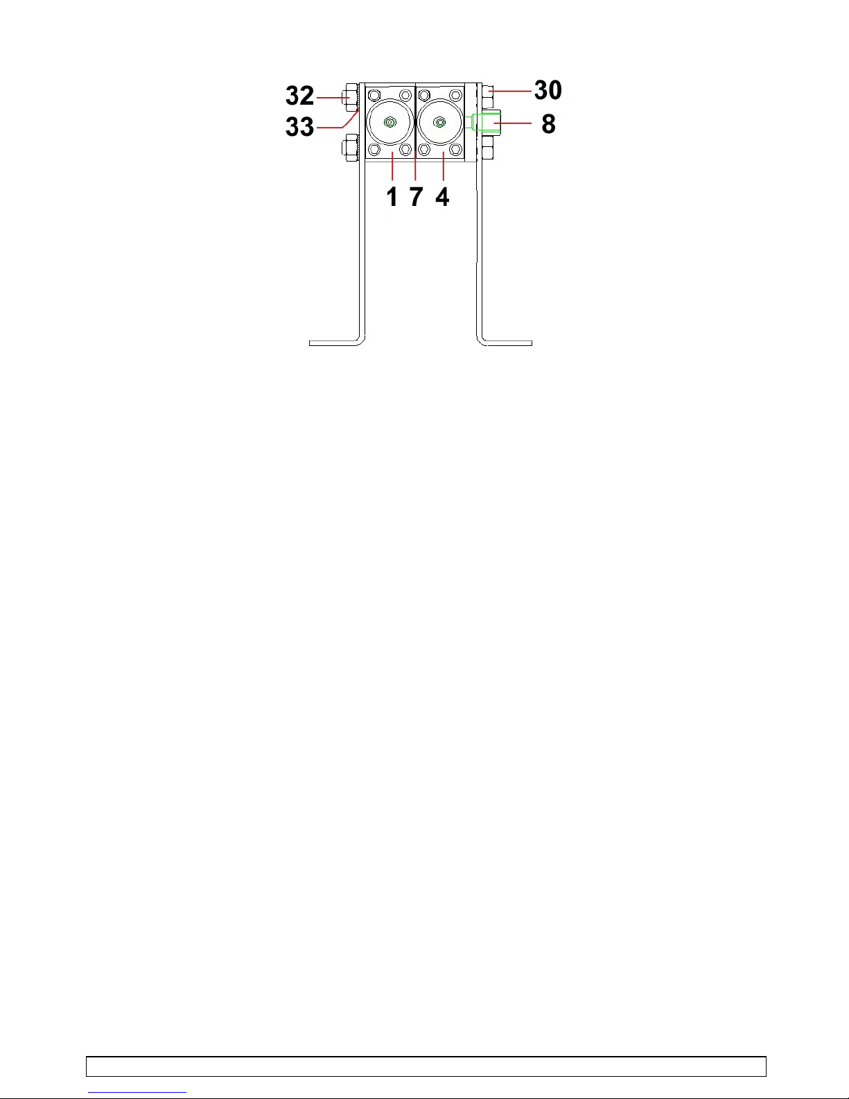
NEW MODULE INSTALLATION (OR MODULE REPLACEMENT) (REFER TO DOC. 573.187.050)
Unscrew nuts (32).
Remove washers (33).
Carry out the same operation for the second tie-rod.
Remove both tie-rods (30).
Mount the new module (be certain seal (7) is installed between two modules).
Slide the appropriate tie-rods through the modules, from fluid outlet flange to the end
module.
Be careful when positioning tie-rods (30), tie-rods head against fluid outlet flange
(8).
Install washers (33) and then screw nuts (32).
SAMES KREMLIN Page 37 Manual : 573.191.112

PILOTED VALVES (FLUID VALVES AND TEST VALVES)
CARTRIDGE OF A FLUID VALVE (IND. 9A / 9B / 9C / 9D) (REFER TO DOC. 573.188.050)
Unscrew the 3 screws (7).
Extract the valve from the module body.
Unscrew the needle (1a / 1b / 1c).
Unscrew the cylinder (4a / 4b).
Hold rod carrier (6), unscrew the needle rod and remove cartridge with rod assembly (9a /
9b / 9c / 9d). Remove the seals.
When reassembling :
Change the seals (11a / 11b), lubricate them then install new cartridge (9a / 9b / 9c / 9d) in
cylinder support (2) by pushing it until the cartridge shoulder comes to lean against the
cylinder support shoulder. Then reinstall all the components in the reverse order of
disassembly.
Install the valve in front of the module body.
Centre the cartridge (9a / 9b / 9c / 9d) on the module body and reinstall screws (7).
A 1
C 2
C 2
A 1
A 1
SAMES KREMLIN Page 38 Manual : 573.191.112

PISTON PACKING (Ind. 14)
131415164
8
5
Unscrew the cylinder (4).
Remove the spring (5).
Unscrew the opening signal light (8).
Unscrew the nut (16).
Remove the support washer (15) and the packing (14).
Clean the parts and change them if necessary.
Before reassembling :
Before assembling on the piston (13), take care of shaping the cartridge lip (14) by hand as
shown in the above drawing (cartridge turned up on the piston).
The nut (16) must be glued on the piston (13) with loctite adhesive
(eg : Loctite 222).
Index Instructions Description Part number
A 1
PTFE grease
PTFE grease (10 ml / 0.0026 US gal)
560.440.101
C 2
Low strength
- Anaerobic Adhesive
Loctite 222 (50 ml / 0.013 US gal)
554.180.010
SAMES KREMLIN Page 39 Manual : 573.191.112

INSTRUCTION MANUAL
COLOR CHANGER
Manual : 1812 573.186.112
Date : 20/12/18 - Supersede : 31/05/16
Modif. : Update
TRANSLATION FROM THE ORIGINAL MANUAL
IMPORTANT : Before assembly and start-up, please read and clearly understand all the doc-
uments relating to this equipment (professional use only).
THE PICTURES AND DRAWINGS ARE NON CONTRACTUAL. WE RESERVE THE RIGHT TO MAKE CHANGES WITHOUT PRIOR
NOTICE.
SAMES KREMLIN SAS
l
13, chemin de Malacher
38 240 - MEYLAN - France
: 33 (0)4 76 41 60 60
www.sames-kremlin.com
SAMES KREMLIN Page 1 Manual : 573.186.112
INSTRUCTION MANUAL
COLOR CHANGER
TABLE OF CONTENTS
1. GENERAL SAFETY INSTRUCTIONS ........................................................ .... .... .... ... ........ .... .... ... .... .... .. 2
2. DESCRIPTION ................................................................................. .................................. ..................... 2
3. ASSEMBLING ......................................................................................................................................... 3
4. TECHNICAL FEATURES............ ........ .... .... ... .... .... .... ....... .... .... ... .... .... .... ... ........ .... .... ... .... .... .... ............. 3
5. DISASSEMBLY - ASSEMBLY................................................................................................................ 5
ADDITIONAL
DOCUMENTATIONS :
EU declaration of conformity 578.050.130
Spare parts
Color changer 573.187.050
CTM valve 573.188.050

SAMES KREMLIN Page 2 Manual : 573.186.112
Dear Customer,
You are the owner of our new color c hanger and we would like to take this opportunity to thank
you.
To make sure your investment will provide full satisfaction, special care has been taken by
SAMES KREMLIN during all designing and manufacturing processes.
To obtain the best result, sa fe and efficient operation of your equipment, we advice you to read and
make yourself familiar with this instruction and service manual. Indeed, the non-compliance with
instructions and precautions stated in this manual could reduce the equipment working-life, result in
operating trouble and create unsafe conditions.
1. GENERAL SAFETY INSTRUCTIONS
The personnel involved in operating and servicing this equipment must be aware of all safety
requirements stated in this manual. The workshop supervisor must be certain that the personnel
has perfectly understood the safety instructions and co mplies with them.
Use the equipments only in a well-ventilated area to prevent from serious body injuries, fire and
explosion hazards.
Spraying of some materials may res ult in hazardous working conditions. To protect the operator,
respirator mask, hand cream and glasses are re quired.
The operating pressure of these equipments are particularly high. Consequently, some precau-
tions must be taken in order to prevent from accidents an d from un sa fe wo rkin g cond itio ns.
2. DESCRIPTION
The color changer is composed of several stackings modules .
It enables a quick color change wi thout material handling. As a result, costs through down time and
solvent consumption are dramatically reduced.
Thre is no dead volume thus allowing a full flushing.
It is used on automatic installations and also on optimized manual installation. A color changer
consists of :
1 end module (inlet),
x intermediate modules,
1 outlet flange,
2 tie-rods.
The end module and the intermediate modules are fitted with two air operated valves. Each valve
feeds the central fluid passage with the selected color.
Select the appropriate modules and valves according to the application :
airspray (low pressure),
AIRMIX (medium pressure - 120 bar / 1740 psi),
AIRMIX (high pressure - 200 bar / 2900 psi).
With the required color valves, add a solvent valve for the flushing an d, if necess ary, an additiona l
valve to provide compressed air to speed up the flus hing process.
On a color changer, the number of valves is always an even number.

SAMES KREMLIN Page 3 Manual : 573.186.112
3. ASSEMBLING
The modules are stacked together and secured by tie-rods suitable fo r the number of modules.
If required two wall mounting bracke ts (use screws Ø 6 mm) can be installed on both side of the
color changer.
It is compulsory to fit the solvent valve on the end module, on the opposite side of the fluid
outlet.
4. TECHNICAL FEATURES
Modula rand versatile.
Ease of maintenance (the valves can be removed without dismantling the fluid hoses). Designed
for fluid circulation.
Supplied with valve opening indicator.
Airspray
AIRMIX
120 bar
/ 1740 psi
AIRMIX GT
200 bar
/ 2900 psi
AIRMIX
200 bar
/ 2900 psi
(stainless
steel 316 L)
AIRMIX
200 bar
/
2900
psi
(stainless
steel 316 L
NPTF)
Maximum fluid pressure 8 bar
/ 116 psi
120 bar
/ 1740 psi
200 bar
/ 2900 psi
200 bar
/ 2900 psi
200 bar
/ 2900 psi
Central fluid passage
diameter
8 mm / 5/16" 6 mm / / 1/4" 6 mm / 1/4" 6 mm / 1/4" 6 mm / 1/4"
Air control fitting (ind. 5) For hose 2,7 x 4
Fluid inlet fitting (ind. 4) F 1/4" NPS F 1/4" NPTF
Fluid outlet fitting (ind. 6) F 1/4" NPS
Wetted parts Stainless steel
PTFE seals
Stainless steel
PTFE seals
Stainless steel
GT seals
Stainless steel
316L
PTFE seals
Stainless steel
316L NPTF
Joints en PTFE
& FFKM seals
1 end module (inlet)
2 intermediate module Refer to drawing next page
3 outlet flange

SAMES KREMLIN Page 4 Manual : 573.186.112
Dimensions :
Ind. A B C D * E F G H * I J K L
mm
35 35 25 60 + (N x 35) 165 64,5 36 N x 35 17,5 Ø 6,5 15 185
"
1.38 1.38 1 2.36 + (N x 1.38) 6.50 2.54 1.42 Nx1.38 0.69 0.26 0.59 7.28
Ind. M O P Q R *
mm
176,5 157,5 8 21,5 86 + (N x 35)
"
6.95 6.20 5/16 0.85 3.38 + (N x 1.38)
* N = Number of intermediate module
3
2
1
E
FG
H
I
J
K
D
4
A
B
C
5
6
R
Q
P
LMO

SAMES KREMLIN Page 5 Manual : 573.186.112
5. DISASSEMBLY - ASSEMBLY
Prior to removing a component shut off air and material supplies. Depressurize the system.
NEW MODULE INSTALLATION (OR MODULE REPLACEMENT) (REFER TO DOC. 573.187.050)
Unscrew nuts (32).
Remove washers (33).
Carry out the same operation for the second tie-rod.
Remove both tie-rods (30).
Mount the new module (be certain seal (7) is installed between two modules).
Slide the appropriate tie-rods through the m odules, from fluid outlet flange to the en d
module.
Be careful when positioning tie-rods (30), tie-rods h ead against fluid outlet flange (8).
Install washers (33) and then screw nuts (32).

SAMES KREMLIN Page 6 Manual : 573.186.112
CARTRIDGE OF A FLUID VALVE (IND. 9A / 9B / 9C / 9D) (REFER TO DOC. 573.188.050)
Unscrew the 3 screws (7).
Extract the valve from the module body.
Unscrew the needle (1a / 1b / 1c).
Unscrew the cylinder (4a / 4b).
Hold rod carrier (6), unscrew the needle rod and remove cartridge with rod assembly (9a / 9b
/ 9c / 9d). Remove the seals.
When reassembling :
Change the seals (11a / 11b), lubricate them then install new cartridge (9a / 9b / 9c / 9d) in
cylinder support (2) by pushing it until the cartridge shoulder comes to lean against the
cylinder support shoulder. Then reinstall all the components in the reverse order of
disassembly.
Install the valve in front of the module body.
Centre the cartridge (9a / 9b / 9c / 9d) on the module body and reinstall screws (7).
A 1
C 2
C 2
A 1 A 1

SAMES KREMLIN Page 7 Manual : 573.186.112
Comply with the dimension value A (1+9+6+8a).
A (mm)
Airspray valve 78.5 / 3.09
AIRMIX valve 120 bar / 1740 psi 77 / 3.03
AIRMIX valve 200 bar / 2900 psi
82.9 / 3.26
AIRMIX valve 200 bar / 2900 psi (stainless steel 316 L)
AIRMIX valve 200 bar / 2900 psi (stainless steel 316 L NPTF)

SAMES KREMLIN Page 8 Manual : 573.186.112
PISTON PACKING (IND. 14)
131415164
8
5
Unscrew the cylinder (4).
Remove the spring (5).
Unscrew the valve opening indicator (8).
Unscrew the nut (16).
Remove the support washer (15) and the packing (14).
Clean the parts and replace them if it is ne cessa ry.
Prior to their reassembly on piston (13), packing lip (14) must be shaped by hand as shown as
above (packing turned up on the piston).
Glue the nut (16) on the piston (13) with a light coating of glue (eg : Loctite 222).
Index Instructions Description Part number
A 1
PTFE grease
PTFE grease (10 ml / 0.0026 US gal)
560.440.101
C 2
Low strength
- Anaerobic Adhesive
Loctite 222 (50 ml / 0.013 US gal)
554.180.010

SAMES KREMLIN 1 Doc. / Dok. 573.705.070
1901 573.705.070
REMPLACEMENT
REPLACEMENT
AUSTAUCH
CAMBIO
llCYCLOMIX™
REMPLACEMENT DES DEBITMETRES ET CAPTEURS
FLOWMETERS AND SENSORS REPLACEMENT
AUSTAUCH DES MESSZELLEN UND SENSOREN
CAMBIO DE LOS CAUDALÍMETROS
NOTICE ORIGINALE
/ TRANSLATION FROM THE ORIGINAL MANUAL
/ ÜBERSETZUNG DER O RIGINAL BETRIEBSANLEITUNG
/ TRADUCCIÓN DEL LIBRO ORIGINAL

SAMES KREMLIN 2 Doc. / Dok. 573.705.070
#
CYCLOMIX™ MULTI
3
155.660.81X
CYCLOMIX™ MULTI PH
4 - 5
155.660.51X
CYCLOMIX™ MICRO, MICRO+ & MICRO+ PH
6 - 7
155.660.9XX
CYCLOMIX™ MICRO+ PH+
7
NC / NS
REMPLACEMENT DES PIECES
REPLACEMENT OF THE PARTS
AUSTAUCH DER TEILE
CAMBIO DE LAS PIEZAS
8 - 10
-
A partir d'août 2014 de nouveaux débitmètres et capteurs seront installés sur nos machines.
Il y aura une phase de transition pendant laquelle il est possible que vous disposiez des anciens débimètres et capteurs sur la
partie CATA et des nouveaux débimètres et capteurs sur la partie BASE. Cette combinaison d’éléments n’altère ni la qualité de
dosage ni la fiabilité de l’équipement.
From August 2014 new flowmeters and sensors will be installed on our machines.
There will be a transition phase during which you may have the former flowmeters and sensors on the CATA part and the new
flowmeters and sensors on the BASE part. This combination of elements affects neither the mixing ratio quality nor the equipment
reliability.
Seit August 2014 werden in unsere Anlagen neue Messzellen und Sensoren eingebaut.
In einer Übergangsphase kann es sein, dass an der Maschine alte und neue Volumenmessgeräte nebeneinander eingebaut sind.
Dies hat keinerlei Einfluss auf die Mischqualität und Zuverlässigkeit der Anlage.
A partir de Agosto de 2014, se instalarán nuevos caudalímetros y captadores en nuestras máquinas.
Durante una fase de transición, es posible encontrar anteriores caudalímetros y captadores en la parte CATA y nuevos en la
parte BASE. La combinación de los dos no afecta ni la calidad de dosificación ni la fiabilidad del equipo.

SAMES KREMLIN 3 Doc. / Dok. 573.705.070
CYCLOMIXTM MULTI
Se reporter à / Refer to / Siehe / Consultar
doc. / dok. 573.344.050
Anciens débitmètres et capteurs / Former flowmeter and sensor
/ Alte Messzellen und Sensoren / Caudalímetros y captadores anteriores
Attention ce débimètre n’est plus commercialisé (pour machine dont le numéro de série est antérieur à 14Y1124)
/ Caution this flowmeter is not serviceable any more (for machine which part number is prior to 14Y1124)
/ Achtung dieses Messzelle ist nicht mehr lieferbar (für Maschine mit der Seriennummer kleiner als 14Y1124)
/ Cuidado Este caudalímetro no se suministra más (para máquina cuyo número de serie es anterior a 14Y1124)
Ind # Désignation Description Bezeichnung Denominación Qté
- 155 660 011 Ensemble compteur Meter assembly Volumenmessgerät kpl. Conjunto contador 2
42a 055 660 001 Débitmètre Flowmeter Messzelle Caudalímetro 2
- 109 100 106 Joint (les 2) Seal (pack of 2) Dichtung (Satz à 2) Junta (bolsa de 2) 1
43a 910 060 102 Capteur Sensor Sensor Captador 2
43a
42a

SAMES KREMLIN 4 Doc. / Dok. 573.705.070
Nouveaux débitmètres et capteurs / New flowmeter and sensor
/ Neue Messzellen und Sensoren / Nuevos caudalímetro y captador
Ind # Désignation Description Bezeichnung Denominación Qté
- 155 660 078 Ensemble compteur Meter assembly Volumenmessgerät kpl. Conjunto contador 2
42 155 660 041 Débitmètre Flowmeter Messzelle Caudalímetro 1
- 155 660 082 Joint (x 1) Seal (pack of 1) Dichtung (1 St.) Junta (bolsa de 1) 1
- 155 660 086 Ensemble capteur Sensor assembly Sensor Einheit Conjunto captador 1
43 910 060 106 Capteur Sensor Sensor Captador 1
- NC / NS Connecteur Connector Anschluss Conectador 1
Ind # Désignation Description Bezeichnung Denominación Qté
* 155 660 165 Pochette de
maintenance débitmètre
(ind. 42 + joint)
Servicing kit Flowmeter (ind. 42
+ seal)
Servicekit für Messzelle
(Pos. 42 + Dichtung)
Bolsa de
mantenimiento
caudalímetro (índ. 42
+ junta)
1
42
43

SAMES KREMLIN 5 Doc. / Dok. 573.705.070
CYCLOMIXTM MULTI PH
Se reporter à / Refer to / Siehe / Consultar
doc. / dok. 573.358.050
Anciens débitmètres et capteurs / Former flowmeters and sensors
/ Alte Messzellen und Sensoren / Caudalímetros y captadores anteriores
Attention ce débimètre n’est plus commercialisé (pour machine
dont le numéro de série est antérieur à 14Y1124)
/ Caution this flowmeter is not serviceable any more (for machine
which part number is prior to 14Y1124)
/ Achtung dieses Messzelle ist nicht mehr lieferbar (für Maschine
mit der Seriennummer kleiner als 14Y1124)
/ Cuidado Este caudalímetro no se suministra más (para máquina
cuyo número de serie es anterior a 14Y1124)
Pour machine dont le numéro de série est antérieur à 14Y1139
/ For machine which part number is prior to 14Y1139
/ Für Maschine mit der Seriennummer kleiner als 14Y1139
/ Para máquina cuyo número de serie es anterior a 14Y1139
Ind # Désignation Description Bezeichnung Denominación Qté
- 155 660 011 Ensemble compteur
(BASE)
Meter assembly (BASE) Volumenmessgerät kpl.
(BASIS)
Conjunto contador
(BASE)
2
42d 055 660 001 Débitmètre (BASE) Flowmeter (BASE) Messzelle (BASIS) Caudalímetro (BASE) 1
- 109 100 106 Joint (les 2) Seal (pack of 2) Dichtung (Satz à 2) Junta (bolsa de 2) 1
43d 910 060 102 Capteur Sensor Sensor Captador 1
- NC / NS Ensemble compteur
(CATA)
Meter assembly (CATA) Volumenmessgerät kpl.
(HÄRTER)
Conjunto contador
(CATA)
1
42c 055 660 501 Débitmètre (CATA)
(inox 316 L)
Flowmeter (CATA)
(stainless steel, 316 L)
Messzelle (HÄRTER)
(Edelstahl 316L)
Caudalímetro (CATA)
(inox 316 L)
1
43c 910 060 102 Capteur Sensor Sensor Captador 2
43d
42c
43c
42d

SAMES KREMLIN 6 Doc. / Dok. 573.705.070
Nouveaux débitmètres et capteurs / New flowmeters and sensors
/ Neue Messzellen und Sensoren / Nuevos caudalímetros y captadores
Ind # Désignation Description Bezeichnung Denominación Qté
- 155 660 078 Ensemble compteur
(BASE)
Meter assembly (BASE) Volumenmessgerät kpl.
(BASIS)
Conjunto contador
(BASE)
1
42a 155 660 041 Débitmètre (BASE) Flowmeter (BASE) Messzelle (BASIS) Caudalímetro (BASE) 1
- 155 660 082 Joint (x 1) Seal (pack of 1) Dichtung (1 St.) Junta (bolsa de 1) 1
- 155 660 086 Ensemble capteur Sensor assembly Sensor Einheit. Conjunto captador 1
43a 910 060 106 Capteur Sensor Sensor Captador 1
- NC / NS Connecteur Connector Anschluss Conectador 1
- 155 660 079 Ensemble compteur
(CATA)
Meter assembly (CATA) Volumenmessgerät kpl.
(HÄRTER)
Conjunto contador
(CATA)
1
42b 155 660 042 Débitmètre (CATA)
(inox 316 L)
Flowmeter (CATA)
(stainless steel, 316 L)
Messzelle (HÄRTER)
(Edelstahl 316L)
Caudalímetro (CATA)
(inox 316 L)
1
- 155 660 082 Joint (x 1) Seal (pack of 1) Dichtung (1 St.) Junta (bolsa de 1) 1
- 155 660 086 Ensemble capteur Sensor assembly Sensor Einheit Conjunto captador 1
43b 910 060 106 Capteur Sensor Sensor Captador 1
- NC / NS Connecteur Connector Anschluss Conectador 1
Ind # Désignation Description Bezeichnung Denominación Qté
* 155 660 165 Pochette de
maintenance débitmètre
(ind. 42a + joint)
Servicing kit Flowmeter (ind. 42a
+ seal)
Servicekit für Messzelle
(Pos. 42a + Dichtung)
Bolsa de
mantenimiento
caudalímetro (índ. 42a
+ junta)
1
*
155 660 166 Pochette de
maintenance débitmètre
(ind. 42b+ joint)
Servicing kit Flowmeter (ind. 42b
+ seal)
Servicekit für Messzelle
(Pos. 42b + Dichtung)
Bolsa de
mantenimiento
caudalímetro (índ. 42b
+ junta)
1
42a
42b
43a
43b

SAMES KREMLIN 7 Doc. / Dok. 573.705.070
CYCLOMIXTM MICRO - CYCLOMIXTM MICRO+ - CYCLOMIXTM MICRO+ PH
- CYCLOMIXTM MICRO+ PH+
Se reporter à / Refer to / Siehe / Consultar
doc. / dok. 573.359.050
Anciens débitmètres et capteurs / Former flowmeters and sensors
/ Alte Messzellen und Sensoren / Caudalímetros y captadores anteriores
Attention ce débimètre n’est plus commercialisé (pour machine
dont le numéro de série est antérieur à 14Y1124)
/ Caution this flowmeter is not serviceable any more (for machine
which part number is prior to 14Y1124)
/ Achtung dieses Messzelle ist nicht mehr lieferbar (für Maschine
mit der Seriennummer kleiner als 14Y1124)
/ Cuidado Este caudalímetro no se suministra más (para máquina
cuyo número de serie es anterior a 14Y1124)
Pour machine dont le numéro de série est antérieur à 14Y1139
/ For machine which part number is prior to 14Y1139
/ Für Maschine mit der Seriennummer kleiner als 14Y1139
/ Para máquina cuyo número de serie es anterior a 14Y1139
CYCLOMIX
TM
MICRO & CYCLOMIXTM MICRO+
Ind # Désignation Description Bezeichnung Denominación Qté
- 155 660 011 Ensemble compteur Meter assembly Volumenmessgerät kpl. Conjunto contador 2
12e 055 660 001 Débitmètre Flowmeter Messzelle Caudalímetro 1
- 109 100 106 Joint (les 2) Seal (pack of 2) Dichtung (Satz à 2) Junta (bolsa de 2) 1
14e 055 660 002 Capteur Sensor Sensor Captador 1
CYCLOMIX
TM
MICRO+ PH
Ind # Désignation Description Bezeichnung Denominación Qté
- 155 660 011 Ensemble compteur
(BASE)
Meter assembly (BASE) Volumenmessgerät kpl.
(BASIS)
Conjunto contador
(BASE)
1
12d 055 660 001 Débitmètre (BASE) Flowmeter (BASE) Messzelle (BASE) Caudalímetro (BASE) 1
- 109 100 106 Joint (les 2) Seal (pack of 2) Dichtung (Satz à 2) Junta (bolsa de 2) 1
14d 055 660 002 Capteur Sensor Sensor Captador 1
- NC / NS Ensemble compteur
(CATA)
Meter assembly (CATA) Volumenmessgerät kpl.
(HÄRTER)
Conjunto contador
(CATA)
1
12b 055 660 501 Débitmètre (CATA)
(inox 316 L)
Flowmeter (CATA)
(stainless steel, 316 L)
Messzelle (HÄRTER)
(Edelstahl 316 L)
Caudalímetro (CATA)
(inox 316 L)
1
14b 055 660 002 Capteur Sensor Sensor Captador 1
14e & 14b
12e & 12d
12e & 12b
14e & 14d

SAMES KREMLIN 8 Doc. / Dok. 573.705.070
Nouveaux débitmètres et capteurs / New flowmeters and sensors
/ Neue Messzelle und Sensor / Nuevos caudalímetros y captadores
CYCLOMIX
TM
MICRO & CYCLOMIXTM MICRO+
Ind # Désignation Description Bezeichnung Denominación Qté
*- 155 660 078 Ensemble compteur Meter assembly Volumenmessgerät kpl. Conjunto contador 2
*12 155 660 041 Débitmètre Flowmeter Messzelle Caudalímetro 1
*- 155 660 082 Joint (x 1) Seal (pack of 1) Dichtung (1 St.) Junta (bolsa de 1) 1
*- 155 660 086 Ensemble capteur Sensor assembly Sensor Einheit Conjunto captador 1
*14 910 060 106 Capteur Sensor Sensor Captador 1
- NC / NS Connecteur Connector Anschluss Conectador 1
Ind # Désignation Description Bezeichnung Denominación Qté
* 155 660 165 Pochette de
maintenance débitmètre
(ind. 12 + joint)
Servicing kit Flowmeter (ind. 12
+ seal)
Servicekit für Messzelle
(Pos. 12 + Dichtung)
Bolsa de
mantenimiento
caudalímetro (índ. 12
+ junta)
1
MICRO+ PH
Ind # Désignation Description Bezeichnung Denominación Qté
- 155 660 078 Ensemble compteur
(BASE)
Meter assembly (BASE) Volumenmessgerät kpl.
(BASIS)
Conjunto contador
(BASE)
1
*
12a
155 660 041 Débitmètre (BASE) Flowmeter (BASE) Messzelle (BASIS) Caudalímetro (BASE) 1
*- 155 660 082 Joint (x 1) Seal (pack of 1) Dichtung (1 St.) Junta (bolsa de 1) 1
*- 155 660 086 Ensemble capteur Sensor assembly Sensor Einheit Conjunto captador 1
*
14a
910 060 106 Capteur Sensor Sensor Captador 1
- NC / NS Connecteur Connector Anschluss Conectador 1
*- 155 660 079 Compteur (CATA) Meter (CATA) Volumenmessgerät kpl.
(HÄRTER)
Contador (CATA) 1
*
12c
155 660 042 Débitmètre (CATA)
(inox 316 L)
Flowmeter (CATA)
(stainless steel, 316 L)
Messzelle (HÄRTER)
(Edelstahl 316 L)
Caudalímetro (CATA)
(inox 316 L)
1
*- 155 660 082 Joint (x 1) Seal (pack of 1) Dichtung (1 St.) Junta (bolsa de 1) 1
*- 155 660 086 Ensemble capteur Sensor assembly Sensor Einheit Conjunto captador 1
*
14c
910 060 106 Capteur Sensor Sensor Captador 1
- NC / NS Connecteur Connector Anschluss Conectador 1
12 & 12a
12c
14 & 14a 14c

SAMES KREMLIN 9 Doc. / Dok. 573.705.070
Ind # Désignation Description Bezeichnung Denominación Qté
* 155 660 165 Pochette de
maintenance débitmètre
(ind. 12a + joint)
Servicing kit Flowmeter (ind. 12a
+ seal)
Servicekit für Messzelle
(Pos. 12a + Dichtung)
Bolsa de
mantenimiento
caudalímetro (índ. 12a
+ junta)
1
*
155 660 166 Pochette de
maintenance débitmètre
(ind. 12c+ joint)
Servicing kit Flowmeter (ind. 12c
+ seal)
Servicekit für Messzelle
(Pos. 12c + Dichtung)
Bolsa de
mantenimiento
caudalímetro (índ. 12c
+ junta)
1
MICRO+ PH+
Ind # Désignation Description Bezeichnung Denominación Qté
*- 155 660 078 Ensemble compteur
(BASE)
Meter assembly (BASE) Volumenmessgerät kpl.
(BASIS)
Conjunto contador
(BASE)
1
*
12a
155 660 041 Débitmètre (BASE) Flowmeter (BASE) Messzelle (BASIS) Caudalímetro (BASE) 1
*- 155 660 082 Joint (x 1) Seal (pack of 1) Dichtung (1 St.) Junta (bolsa de 1) 1
*- 155 660 086 Ensemble capteur Sensor assembly Sensor Einheit Conjunto captador 1
*
14a
910 060 106 Capteur Sensor Sensor Captador 1
- NC / NS Connecteur Connector Anschluss Conectador 1
11d NC / NS Compteur (CATA) Meter (CATA) Volumenmessgerät kpl.
(HÄRTER)
Contador (CATA) 1
*
12d
NC / NS Débitmètre (CATA)
(inox 316 L)
Flowmeter (CATA)
(stainless steel, 316 L)
Messzelle (HÄRTER)
(Edelstahl 316 L)
Caudalímetro (CATA)
(inox 316 L)
1
*- 155 660 082 Joint (x 1) Seal (pack of 1) Dichtung (1 St.) Junta (bolsa de 1) 1
*- 155 660 086 Ensemble capteur Sensor assembly Sensor Einheit Conjunto captador 1
*
14c
910 060 106 Capteur Sensor Sensor Captador 1
- NC / NS Connecteur Connector Anschluss Conectador 1
Ind # Désignation Description Bezeichnung Denominación Qté
* 155 660 165 Pochette de
maintenance débitmètre
(ind. 12a + joint)
Servicing kit Flowmeter (ind. 12a
+ seal)
Servicekit für Messzelle
(Pos. 12a + Dichtung)
Bolsa de
mantenimiento
caudalímetro (índ. 12a
+ junta)
1
*
155 660 166 Pochette de
maintenance débitmètre
(ind. 12c+ joint)
Servicing kit Flowmeter (ind. 12c
+ seal)
Servicekit für Messzelle
(Pos. 12c + Dichtung)
Bolsa de
mantenimiento
caudalímetro (índ. 12c
+ junta)
1

SAMES KREMLIN 10 Doc. / Dok. 573.705.070
REMPLACEMENT DES ANCIENS DEBITMETRES ET CAPTEURS
/ FORMER FLOWMETERS AND SENSORS REPLACEMENT
/ ASTAUCH DER ALTEN MESSZELLEN UND SENSOREN
/ CAMBIO DE LOS ANTERIORES CAUDALIMETROS Y CAPTADORES
Si vous devez remplacer l’une des pièces suivantes
/ In case of replacement of one of the following parts
/ Wenn Sie eines dieser Teile ersetzen müssen
/ Si Vd. tiene que cambiar una de las piezas siguientes
Vous devez commander
/ You must order
/ Müssen Sie folgendes bestellen
/ Vd. debe encargar
# 055 660 001
# 910 060 102
# 055 660 001 + 910 060 102
# 055 660 501
# 910 060 102
# 055 660 501 + 910 060 102
# 155 660 078
# 155 660 079

SAMES KREMLIN 11 Doc. / Dok. 573.705.070
Si vous devez remplacer l’une des pièces suivantes
/ In case of replacement of one of the following parts
/ Wenn Sie eines dieser Teile ersetzen müssen
/ Si vd. tiene que cambiar una de las piezas siguientes
Vous devez commander
/ You must order
/ Müssen Sie folgendes bestellen
/ Vd. debe encargar
# 055 660 001
# 055 660 002
# 055 660 001 + 055 660 002
# 055 660 501
# 055 660 002
# 055 660 501 + 055 660 002
# 155 660 078
# 155 660 079

SAMES KREMLIN 12 Doc. / Dok. 573.705.070
Nota : Pour effectuer ce changement il n'est pas nécessaire de refaire le câblage connecteur.
Nota : To replace these elements, you do not need to make the connector cabling again.
Anmerkung : Wenn Sie diese Teile ersetzen, brauchen Sie die Kabel nicht erneuern.
Nota : Para llevar a cabo este cambio, no se necesita hacer de nuevo el cableado del conectador.

Doc. 573.359.050
Date/Datum/Fecha : 07/12/18
Annule/Cancels/
Ersetzt/Anula : 23/01/15
Modif. / Änderung :
Mise à jour / Update / Aktualisierung
/ Actualización
Pièces de rechange
Spare parts list
Ersatzteilliste
Piezas de repuesto
SYSTEME DE DOSAGE ELECTRONIQUE
MIXING SYSTEM
ELEKTRONISCHE 2-K-ANLAGE
SISTEMA DE DOSIFICACIÓN
CYCLOMIXTM MICRO
CYCLOMIX
TM
MICRO+
CYCLOMIX
TM
MICRO+ PH
CYCLOMIX
TM
MICRO+ PH+
CYCLOMIXTM MICRO+ PH
Sans mélangeur, avec circuit catalyseur en inox 316 L
Without mixer, with catalyst system, stainless steel 316 L
Ohne Mischer, Härtersystem in Edelstahl 316 L
Sin mezclador, con circuito catalizador de inox 316 L
CYCLOMIXTM BASE / BASIS CATA / HÄRTER #
MICRO
1A + 1SA
1B
155.660.900
3A + 1SA
155.660.930
MICRO+
1A + 1SA
1B + 1SB
155.660.911
3A + 1SA
155.660.933
MICRO+ PH
1A + 1SA
1B + 1SB
155.660.951
3A + 1SA
155.660.953
MICRO+ PH+
1A + 1SA
1B + 1SB
997.202.611
3A + 1SA
997.202.631
A : Base / Basis SA : solvant / solvent / Verdünnung / disolvente base / Basis
B : Cata / Härter SB :
solvant / solvent / Verdünnung / disolvente cata / Härter

SAMES KREMLIN 2 Doc. / Dok. 573.359.050
BAIE DE COMMANDE / CONTROL CABINET / STEUERGEHÄUSE / ARMARIO DE MANDO
Ind # Désignation Description Bezeichnung Denominación Qté
*1 155 660 917 Carte µ avec afficheur µ card with display unit Elektronische Karte mit
integriertem Display
Carta µ con visualizador 1
2 055 660 918 Façade Front part Frontplatte Parte delantera 1
- 901 280 192 Interrupteur Switch Schalter Interruptor 1
3 155 660 925 Ensemble capteur et
aimant
Sensor and magnet
assembly
Sensor und Magnet
Einheit
Conjunto captador e
imán
4
- 901 280 193 Buzzer 24V - 100 db Buzzer 24V - 100 db Summer 24V - 100 dB Sirena 24V - 100 db 1
PARTIE PRODUIT / MIXING UNIT / MATERIALTEIL / PARTE PRODUCTO
1
2
3

SAMES KREMLIN 3 Doc. / Dok. 573.359.050
CYCLOMIXTM MICRO & CYCLOMIXTM MICRO+
Ind # Désignation Description Bezeichnung Denominación Qté
*10 903 050 525 Débistat Flow switch Fließschalter Debistat 1
*11 155 660 078 Ensemble compteur
(voir détail)
Meter assembly
(see detail)
Volumenmessgerät kpl.
(siehe Detail)
Conjunto contador
(ver detalle)
2
15a 155 528 010 Clapet HP 200 bar
(voir détail)
HP valve, 200 bar / 2900
psi (see detail)
Ventil HP 200 bar
(siehe Detail)
Válvula AP 200 bar
(ver detalle)
1
16 055 528 002 Bouchon Plug Blindstopfen Tapón 1
17 903 160 510 Clapet anti retour inox Non-return valve,
stainless steel
Rückschlagventil,
Edelstahl
Válvula anti-retorno inox 2
18 055 660 070 Bloc d'injection Injection unit Injektions-Block Bloque de inyección 1
*- 155 660 071 Buse Ø 2 Nozzle, model Ø 2 Düse Ø 2 Boquilla, tipo Ø 2 1
*19 155 660 080 Ensemble mélangeur
souple (1m - 240 bar)
Flexible mixer assembly
(1 m / 39.4"
- 240 bar / 3480 psi)
Mischer-Schlauch mit
Anschlüssen
(1m - 240 bar)
Conjunto mezclador
flexible (1m - 240 bar)
1
20 903 090 221 Vanne 3 voies FFF 1/4
BSP (inox)
Three way valve FFF 1/4
BSP (stainless steel)
3-Wege Ventile AG AG
AG 1/4 BSP (Edelstahl)
Válvula 3 vías HHH 1/4
BSP (inox)
1
21 050 450 651
Tuyau produit ( 4,8
mm, long. 0,6 m,
raccords inox, 240 bar)
Fluid hose (3/16" dia,
0.6 m / 23.6" long,
stainless steel hoses,
240 bar / 3481 psi)
Materialschlauch
( 4,8 mm, Länge: 0,6 m,
Anschlüsse Edelstahl,
240 bar)
Tubería producto
(Ø 4,8 mm, 0,6 m de
largo, racores de inox,
240 bar)
1
22 901 250 216 Cordon de liaison
(lg. 5 m)
Connecting bead
(length 5 m / 196.85")
Verbindungskabel
(Länge 5 M)
Cordón de conexión
(5 m de largo)
1
30 000 972 025 Raccord produit droit
(M 1/4 NPT - M 1/2 JIC)
Straight fluid fitting
(M 1/4 NPT - M 1/2 JIC)
Gewindenippel (AG 1/4
NPT - AG 1/2 JIC)
Racor recto producto
(M 1/4 NPT - M 1/2 JIC)
x
31 905 210 602 Raccord coudé inox
(M 1/4 NPT - M 1/2 JIC)
Elbow fitting, stainless
steel (male 1/4 NPT male # 5 JIC)
Winkelnippel, Edelstahl
(AG 1/4 NPT - AG 1/2
JIC)
Racor acodado inox
(M 1/4 NPT - M 1/2 JIC)
x
41 903 050 516 Electrovannes 24V DC Electrovalves, 24V DC Elekroventil 24V DC Electroválvulas 24V DC x
42 903 050 517 Embase Base Anschlussplatte Base x
43 903 050 518 Embase juxtaposable Base Anschlussplatte Base 1
50 - Ensemble changement de
teintes (voir détail)
Color changer assembly
(see detail)
Farbwechselblock
(siehe Detail)
Conjunto cambiador de
tintes (ver detalle)
x
CYCLOMIXTM MICRO+ PH
Pièces spécifiques - Specific parts - Spezifische Teile - Partes específicas
ind # Désignation Description Bezeichnung Denominación Qté
11a 155 660 078 Ensemble compteur
(BASE) (voir détail)
Meter assembly (BASE)
(see detail)
Volumenmessgerät kpl.
(BASIS) (siehe Detail)
Conjunto contador
(BASE) (ver detalle)
1
11b NC / NS Ensemble compteur
(CATA) (voir détail)
Meter assembly (CATA)
(see detail)
Volumenmessgerät kpl.
(HÄRTER) (siehe Detail)
Conjunto contador
(CATA) (ver detalle)
1
11c 155 660 079 Ensemble compteur
(CATA) (voir détail)
Meter assembly (CATA)
(see detail)
Volumenmessgerät kpl.
(HÄRTER) (siehe Detail)
Conjunto contador
(CATA) (ver detalle)
1
15b 155 536 500 Clapet 200 bar
(inox 316L)
(voir détail)
Valve, 200 bar / 2900 psi
(stainless steel, 316 L)
(see detail)
Ventil 200 bar
(Edelstahl 316L)
(siehe Detail)
Válvula 200 bar
(inox 316L)
(ver detalle)
1
18 055 660 470 Bloc d'injection
(inox 316L)
Injection unit
(stainless steel, 316 L)
Injektions-Block
(Edelstahl 316L)
Bloque de inyección
(inox 316L)
1

SAMES KREMLIN 4 Doc. / Dok. 573.359.050
CYCLOMIXTM MICRO+ PH+
Pièces spécifiques - Specific parts - Spezifische Teile - Partes específicas
ind # Désignation Description Bezeichnung Denominación Qté
11a 155 660 078 Ensemble compteur
(BASE) (voir détail)
Meter assembly (BASE)
(see detail)
Volumenmessgerät kpl.
(BASIS) (siehe Detail)
Conjunto contador
(BASE) (ver detalle)
1
11d NC / NS Ensemble compteur
(CATA) (voir détail)
Meter assembly (CATA)
(see detail)
Volumenmessgerät kpl.
(HÄRTER) (siehe Detail)
Conjunto contador
(CATA) (ver detalle)
1
11e NC / NS Ensemble compteur
(CATA) (voir détail)
Meter assembly (CATA)
(see detail)
Volumenmessgerät kpl.
(HÄRTER) (siehe Detail)
Conjunto contador
(CATA) (ver detalle)
1
15c 155 662 030 Clapet 200 bar
(inox 316L NPTF)
(voir détail)
Valve, 200 bar / 2900 psi
(stainless steel, 316 L
NPTF) (see detail)
Ventil 200 bar
(Edelstahl 316L NPTF)
(siehe Detail)
Válvula 200 bar
(inox 316L NPTF)
(ver detalle)
1
18 055 660 470 Bloc d'injection
(inox 316L)
Injection unit
(stainless steel, 316 L)
Injektions-Block
(Edelstahl 316L)
Bloque de inyección
(inox 316L)
1

SAMES KREMLIN 5 Doc. / Dok. 573.359.050
DEBITMETRES ET CAPTEURS / FLOWMETERS AND SENSORS
MESSZELLEN UND SENSOREN / CAUDALÍMETROS Y CAPTADORES
Anciens débitmètres et capteurs / Former flowmeters and sensors
/ Alte Messzellen und Sensoren / Caudalímetros y captadores anteriores
CYCLOMIX
TM
MICRO+ PH
Ind # Désignation Description Bezeichnung Denominación Qté
11b NC / NS Ensemble compteur
(CATA)
Meter assembly (CATA) Volumenmessgerät kpl.
(HÄRTER)
Conjunto contador
(CATA)
1
12b 055 660 501 Débitmètre (CATA)
(inox 316 L)
Flowmeter (CATA)
(stainless steel, 316 L)
Messzelle (HÄRTER)
(Edelstahl 316 L)
Caudalímetro (CATA)
(inox 316 L)
1
14b 055 660 002 Capteur Sensor Sensor Captador 1
Nouveaux débitmètres et capteurs / New flowmeters and sensors
/ Neue Messzellen und Sensoren
/ Nuevos caudalímetros y captadores
CYCLOMIX
TM
MICRO & CYCLOMIXTM MICRO+
Ind # Désignation Description Bezeichnung Denominación Qté
*11 155 660 078 Ensemble compteur Meter assembly Volumenmessgerät kpl. Conjunto contador 2
*12 155 660 041 Débitmètre Flowmeter Messzelle Caudalímetro 1
*- 155 660 082 Joint (x 1) Seal (pack of 1) Dichtung (1 St.) Junta (bolsa de 1) 1
*- 155 660 086 Ensemble capteur Sensor assembly Sensor kpl. Conjunto captador 1
*14 910 060 106 Capteur Sensor Sensor Captador 1
- NC / NS Connecteur Connector Anschluss Conectador 1
Ind # Désignation Description Bezeichnung Denominación Qté
* 155 660 165 Pochette de
maintenance débitmètre
(ind. 12 + joint)
Servicing kit Flowmeter (ind. 12
+ seal)
Servicekit für Messzelle
(Pos. 12 + Dichtung)
Bolsa de
mantenimiento
caudalímetro (índ. 12
+ junta)
1
12 & 12a
12c
14 & 14a 14c
14b
12b

SAMES KREMLIN 6 Doc. / Dok. 573.359.050
MICRO+ PH
Ind # Désignation Description Bezeichnung Denominación Qté
*
11a
155 660 078 Ensemble compteur
(BASE)
Meter assembly (BASE) Volumenmessgerät kpl.
(BASIS)
Conjunto contador
(BASE)
1
*
12a
155 660 041 Débitmètre (BASE) Flowmeter (BASE) Messzelle (BASIS) Caudalímetro (BASE) 1
*- 155 660 082 Joint (x 1) Seal (pack of 1) Dichtung (1 St.) Junta (bolsa de 1) 1
*- 155 660 086 Ensemble capteur Sensor assembly Sensor kpl. Conjunto captador 1
*
14a
910 060 106 Capteur Sensor Sensor Captador 1
- NC / NS Connecteur Connector Anschluss Conectador 1
*
11c
155 660 079 Compteur (CATA) Meter (CATA)
Volumenmessgerät kpl.
(HÄRTER)
Contador (CATA) 1
*
12c
155 660 042 Débitmètre (CATA)
(inox 316 L)
Flowmeter (CATA)
(stainless steel, 316 L)
Messzelle (HÄRTER)
(Edelstahl 316 L)
Caudalímetro (CATA)
(inox 316 L)
1
*- 155 660 082 Joint (x 1) Seal (pack of 1) Dichtung (1 St.) Junta (bolsa de 1) 1
*- 155 660 086 Ensemble capteur Sensor assembly Sensor kpl. Conjunto captador 1
*
14c
910 060 106 Capteur Sensor Sensor Captador 1
- NC / NS Connecteur Connector Anschluss Conectador 1
Ind # Désignation Description Bezeichnung Denominación Qté
* 155 660 165 Pochette de
maintenance débitmètre
(ind. 12a + joint)
Servicing kit Flowmeter (ind. 12a
+ seal)
Servicekit für Messzelle
(Pos. 12a + Dichtung)
Bolsa de
mantenimiento
caudalímetro (índ. 12a
+ junta)
1
* 155 660 166 Pochette de
maintenance débitmètre
(ind. 12c + joint)
Servicing kit Flowmeter (ind. 12c
+ seal)
Servicekit für Messzelle
(Pos. 12c + Dichtung)
Bolsa de
mantenimiento
caudalímetro (índ. 12c
+ junta)
1

SAMES KREMLIN 7 Doc. / Dok. 573.359.050
MICRO+ PH+
Ind # Désignation Description Bezeichnung Denominación Qté
*
11a
155 660 078 Ensemble compteur
(BASE)
Meter assembly (BASE) Volumenmessgerät kpl.
(BASIS)
Conjunto contador
(BASE)
1
*
12a
155 660 041 Débitmètre (BASE) Flowmeter (BASE) Messzelle (BASIS) Caudalímetro (BASE) 1
*- 155 660 082 Joint (x 1) Seal (pack of 1) Dichtung (1 St.) Junta (bolsa de 1) 1
*- 155 660 086 Ensemble capteur Sensor assembly Sensor kpl. Conjunto captador 1
*
14a
910 060 106 Capteur Sensor Sensor Captador 1
- NC / NS Connecteur Connector Anschluss Conectador 1
11d NC / NS Compteur (CATA) Meter (CATA)
Volumenmessgerät kpl.
(HÄRTER)
Contador (CATA) 1
*
12d
NC / NS Débitmètre (CATA)
(inox 316 L)
Flowmeter (CATA)
(stainless steel, 316 L)
Messzelle (HÄRTER)
(Edelstahl 316 L)
Caudalímetro (CATA)
(inox 316 L)
1
*- 155 660 082 Joint (x 1) Seal (pack of 1) Dichtung (1 St.) Junta (bolsa de 1) 1
*- 155 660 086 Ensemble capteur Sensor assembly Sensor kpl. Conjunto captador 1
*
14c
910 060 106 Capteur Sensor Sensor Captador 1
- NC / NS Connecteur Connector Anschluss Conectador 1
Ind # Désignation Description Bezeichnung Denominación Qté
* 155 660 165 Pochette de
maintenance débitmètre
(ind. 12a + joint)
Servicing kit Flowmeter (ind. 12a
+ seal)
Servicekit für Messzelle
(Pos. 12a + Dichtung)
Bolsa de
mantenimiento
caudalímetro (índ. 12a
+ junta)
1
* 155 660 166 Pochette de
maintenance débitmètre
(ind. 12c + joint)
Servicing kit Flowmeter (ind. 12c
+ seal)
Servicekit für Messzelle
(Pos. 12c + Dichtung)
Bolsa de
mantenimiento
caudalímetro (índ. 12c
+ junta)
1
Nota :
A partir d'août 2014
de nouveaux débitmètres et capteurs seront installés sur nos machines.
Il y aura une phase de transition pendant laquelle il est possible que vous disposiez des anciens débimètres et
capteurs sur la partie CATA et des nouveaux débimètres et capteurs sur la partie BASE. Cette combinaison
d’éléments n’altère pas la qualité de dosage ni la fiabilité de l’équipement.
Si vous possédez une machine dont le numéro de série est antérieur à 14Y1139 et que vous désirez remplacer
l’un de vos débimètres ou de vos capteurs merci de vous référer au document 573.705.070.
Nota :
From August 2014
new flowmeters and sensors will be installed on our machines.
There will be a transition phase during wich you may have the former flowmeters and sensors on the CATA part
and of the new flowmeters and sensors on the BASE part. This combination of elements affects neither the
mixing ratio quality nor the equipment reliability.
If you have a machine wich reference number is prior to 14Y1139 and if you want to replace one of your
flowmeters or sensors, please refer to the document 573.705.070.
Anmerkung : Seit August 2014 werden in unsere Anlagen neue Messzellen und Sensoren eingebaut.
In einer Übergangsphase kann es sein, dass an der Maschine alte und neue Volumenmessgeräte
nebeneinander eingebaut sind. Dies hat keinerlei Einfluss auf die Mischqualität und Zuverlässigkeit der Anlage.
Wenn Sie eine Maschine mit der Seriennummer kleiner als 14Y1139 haben, und Sie wollen eine Messzelle oder
Sensor ersetzen, dann schauen Sie im Dokument 573.705.070 nach.
Nota :
A partir de Agosto de 2014
, se instalarán nuevos caudalímetros y captadores en nuestras máquinas.
Durante una fase de transición, es posible encontrar anteriores caudalímetros y captadores en la parte CATA y
nuevos en la parte BASE. La combinación de los dos no afecta ni la calidad de dosificación ni la fiabilidad del
equipo.
Si tiene una máquina cuyo número de série es anterior a 14Y1139 y si desea cambiar uno de sus caudalímetros
o captadores por favor consulte el documento 573.705.070.

SAMES KREMLIN 8 Doc. / Dok. 573.359.050
CTM : ENSEMBLE CHANGEUR DE TEINTES / COLOR CHANGER ASSEMBLY
/ FARBWECHSELBLOCK / CONJUNTO CAMBIADOR DE TINTES
(AIRMIX® 200 bar / 2900 psi) (Ind. 50)
(Doc. 573.187.050 & 573.188.050)
Ind # Désignation Description Bezeichnung Denominación Qté
51 155 660 020 Ensemble changement de
teintes (1 Base)
Color changer assembly
(1 Base)
Farbwechselblock
(1 Basis)
Conjunto cambiador de
tintes (1Base)
x
52 155 660 931 Ensemble changement de
teintes (3 Bases)
Color changer assembly
(3 Bases)
Farbwechselblock
(3 Basis)
Conjunto cambiador de
tintes (3 bases)
x
53 155 660 020 Ensemble changement de
teintes (1 Cata)
Color changer assembly
(1 Cata)
Farbwechselblock
(1 Härter)
Conjunto cambiador de
tintes (1 Cata)
x
54 - E nsemble changement de
teintes (1 Cata)
inox 316L
Color changer assembly
(1 Cata)
316L stainless steel
Farbwechselblock
(1 Härter)
Edelstahl 316L
Conjunto cambiador de
tintes (1 Cata)
inox 316L
x
55 - E nsemble changement de
teintes (1 Cata)
inox 316L NPTF
Color changer assembly
(1 Cata)
316L NPTF stainless
steel
Farbwechselblock
(1 Härter)
Edelstahl 316L NPTF
Conjunto cambiador de
tintes (1 Cata)
inox 316L NPTF
x
CYCLOMIXTM Base / Basis
Cata / Härter
Ind. 51
(Ind. 70a
+ 73a)
Ind. 52
(Ind. 70a + 71
+ 73a)
Ind. 53
(Ind. 70a
+ 73a)
Ind. 54
(Ind. 70b
+ 73b)
Ind. 55
(Ind. 70c
+ 73b)
MICRO
1A + 1SA / 1B
1
- - - -
3A + 1SA / 1B -
1
- - -
MICRO+
1A + 1SA / 1B + 1SB
1
-
1
- -
3A + 1SA / 1B + 1SB -
1 1
- -
MICRO+ PH
1A + 1SA / 1B + 1SB
1
- -
1
-
3A + 1SA / 1B + 1SB -
1
-
1
-
MICRO+ PH+
1A + 1SA / 1B + 1SB
1
- - -
1
3A + 1SA / 1B + 1SB -
1
- -
1
A : base / Basis B : cata / Härter S : solvant / solvent / Verdünnung / disolvente
77
70a / 70b / 70c
73a / 73b
76
CTM (Ind. 52) CTM (Ind. 51, 53, 54, 55)
70a / 70b / 70c
71
73a / 73b

SAMES KREMLIN 9 Doc. / Dok. 573.359.050
CTM (Ind. 51, 52, 53)
Ind # Désignation Description Bezeichnung Denominación Qté
*70a 155 535 350 Module d'extrémité
AIRMIX® 200 bar
(voir Doc. 573.187.050)
End module
200 bar / 2900 psi
(refer to
Doc. 573. 187.050)
Unteres Modul 200 bar
(siehe Dok. 573.187.050)
Modulo AIRMIX® de
extremidad 200 bar
(consultar Doc.
573.187.050)
1
*71 155 535 450 Module de commutation
AIRMIX® 200 bar
(voir Doc. 573.187.050)
Intermediate module
200 bar / 2900 psi
(refer to
Doc. 573. 187.050)
Zwischen Modul 200 bar
(siehe Dok. 573.187.050)
Modulo AIRMIX®
intermediario 200 bar
(consultar Doc.
573.187.050)
1
*73a 155 535 500 Bride de sortie équipée Flange assembly, outlet
material
Ausgangsflansch, kpl Brida de salida equipada 1
76 906 314 211 Bouchon 1/4 " Plug, 1/4" Blindstopfen 1/4" Tapón 1/4" 2
77 - Ensemble 2 tirants Set of 2 tie-rods Verbindungsbolzen (Satz
mit 2 Stück)
Conjunto de 2 tirantes 1
- 155 535 610 - pour 1 mo du le - for 1 module - für 1 Modul - para 1 modulo -
- 155 535 620 - pour 2 mo du les - for 2 modules - für 2 Module - para 2 modulos -
CTM (Ind. 54) (inox 316L / Stainless steel, 316L / Edelstahl 316L / inox 316L)
Ind # Désignation Description Bezeichnung Denominación Qté
30 905 160 218 Raccord produit tournant
(M 1/4 G - F 1/2 JIC)
Swivel fluid fitting
(M 1/4 G - F 1/2 JIC)
Drehgelenk
(AG 1/4 G - IG 1/2 JIC)
Racor producto giratorio
(M 1/4 G - H 1/2 JIC)
4
*70b 155 536 200 Module d'extrémité
AIRMIX® 200 bar
(inox 316L)
(voir Doc. 573.187.050)
End module
200 bar / 2900 psi
(stainless steel, 316 L)
(refer to
Doc. 573. 187.050)
Unteres Modul 200 bar
(Edelstahl 316L)
(siehe Dok. 573.187.050)
Modulo AIRMIX® de
extremidad 200 bar (inox
316L) (consultar to Doc.
573.187.050)
1
*73b 155 536 410 Bride de sortie équipée
(inox 316L)
(voir Doc. 573.187.050)
Flange assembly, outlet
material (stainless steel,
316 L) (refer to
Doc. 573.187.050)
Ausgangsflansch, kpl
(Edelstahl 316L)
(siehe Dok. 573.187.050)
Brida de salida equipada
(inox 316L) (consultar
Doc. 573.187.050)
1
76 906 314 211 Boucho n 1/4 " inox Plug, 1/4" Blindstopfen 1/4" Tapón 1/4" 2
77 155 535 610 Ensemble 2 tirants Set of 2 tie-rods Verbindungsbolzen (Satz
mit 2 Stück)
Conjunto de 2 tirantes 1
CTM (Ind. 55) (inox 316L NPTF / Stainless steel, 316L NPTF / Edelstahl 316L NPTF / inox 316L NPTF)
Ind # Désignation Description Bezeichnung Denominación Qté
30 905 160 218 Raccord produit tournant
(M 1/4 G - F 1/2 JIC)
Swivel fluid fitting
(M 1/4 G - F 1/2 JIC)
Drehgelenk
(AG 1/4 G - IG 1/2 JIC)
Racor producto giratorio
(M 1/4 G - H 1/2 JIC)
4
*70 c 155 662 050 Module AIRMIX®
d'extrémité (200 bar)
(inox 316 L NPTF) (voir
Doc. 573.187.050)
End module (material or
solvent or air inlet)
(200 bar / 2900 psi)
(stainless steel, 316 L
NPTF) (refer to
Doc. 573.187.050)
Unteres Modul
(Endmodul) (200 bar)
(Edelstahl 316 L NPTF)
(siehe Dok. 573.187.050)
Modulo AIRMIX® de
extremidad (200 bar)
(inox 316 L NPTF)
(consultar Doc.
573.187.050)
1
*73b 155 536 410 Bride de sortie équipée
(inox 316L)
(voir Doc. 573.187.050)
Flange assembly, outlet
material (stainless steel,
316 L) (refer to
Doc. 573.187.050)
Ausgangsflansch, kpl
(Edelstahl 316L)
(siehe Dok. 573.187.050)
Brida de salida equipada
(inox 316L) (consultar
Doc. 573.187.050)
1
76 906 314 211 Bouchon 1/4 " inox P lug, 1/4" Blindstopfen 1/4" Tapón 1/4" 2
77 155 535 610 Ensemble 2 tirants Set of 2 tie-rods Verbindungsbolzen (Satz
mit 2 Stück)
Conjunto de 2 tirantes 1

SAMES KREMLIN 10 Doc. / Dok. 573.359.050
CLAPET PILOTÉ / PILOTED VALVE / VENTIL / VÁLVULA PILOTADA (200 bar / 2900 psi)
Ind. 15a
inox / stainless steel / Edelstahl / inox
# 155.528.010
Ind. 15b
inox 316L / stainless steel, 316L
Edelstahl 316L / inox 316L
# 155.536.500
Ind. 15c
inox 316L NPTF / stainless steel, 316L NPTF
Edelstahl 316L NPTF / inox 316L NPTF
# 155.662.030
68a / 68b / 68c
69a / 69b / 69c
CYCLOMIXTM MICRO & CYCLOMIXTM MICRO+
Ind # Désignation Description Bezeichnung Denominación Qté
68a 055 528 001 Corps Body Körper Cuerpo 1
*69a 155 535 315 Vanne AIRMIX® 200 bar
(voir Doc. 573.188.050)
AIRMIX® valve, 200 bar
/ 2900 psi (refer to
Doc. 573.188.050)
AIRMIX®-Ventil 200 bar
(siehe Dok. 573.188.050)
Válvula AIRMIX® 200 bar
(consultar Doc.
573.188.050)
1
CYCLOMIXTM MICRO+ PH
Ind # Désignation Description Bezeichnung Denominación Qté
68b 055 536 501 Corps (inox 316 L) Body
(stainless steel, 316 L)
Körper
(Edelstahl 316 L)
Cuerpo (inox 316 L) 1
*69b 155 536 300 Vanne AIRMIX® 200 bar
(inox 316 L)
(voir Doc. 573.188.050)
AIRMIX® valve, 200 bar
/ 2900 psi (stainless steel,
316 L) (refer to Doc.
573.188.050)
AIRMIX®-Ventil 200 bar
(Edelstahl 316L)
(siehe Dok. 573.188.050)
Válvula AIRMIX® 200 bar
(inox 316 L)
(consultar Doc.
573.188.050)
1
- 055 528 003 Bouchon pour clapet (inox
316 L)
Plug, valve
(stainless steel, 316 L)
Blindstopfen für Ventil
(Edelstahl 316 L)
Tapón para válvula
(inox 316 L)
1
CYCLOMIXTM MICRO+ PH+
Ind # Désignation Description Bezeichnung Denominación Qté
68c 055 662 031 Corps (inox 316 L NPTF) Body
(stainless steel, 316 L
NPTF)
Körper
(Edelstahl 316 L NPTF)
Cuerpo (inox 316 L
NPTF)
1
*69c 155 662 020 Vanne AIRMIX® 200 bar
(inox 316 L)
(voir Doc. 573.188.050)
AIRMIX® valve, 200 bar
/ 2900 psi (stainless steel,
316 L) (refer to Doc.
573.188.050)
AIRMIX®-Ventil 200 bar
(Edelstahl 316L)
(siehe Dok. 573.188.050)
Válvula AIRMIX® 200 bar
(inox 316 L)
(consultar Doc.
573.188.050)
1

SAMES KREMLIN 11 Doc. / Dok. 573.359.050
ACCESSOIRES - ACCESSORIES - ZUBEHÖR - ACCESORIOS
Ind # Désignation Description Bezeichnung Denominación Qté
- 910 090 102 Gobelet gradué (650 ml) Graduated cup (650 ml) Messbecher (650 ml) Copa graduada (650 ml) 2
- 903 090 806 Vanne F 1/4 BSP
(pour alimentation en air
du pistolet)
Valve, F 1/4 BSP
(for gun air supply)
Ventil, IG 1/4 BSP
(für die Luftversorgung
der Pistole)
Válvula H 1/4 BSP
(para alimentar con aire la
pistola)
1
- - Raccord d'adaptation
pour test "TB" (inox)
Adjustment fitting for
"TB" test (stainless steel)
Anpassunganschluss für
das Ausliterventil “TB”
(Edelstahl)
Racor de adaptación para
prueba "TB" (inox)
1
- 055 660 929 Raccord
F 3/4 JIC - F 1/4 BSP
Fitting,
F 3/4 JIC - F 1/4 BSP
Anschluss
IG 3/4 JIC - IG 1/4 BSP
Racor,
H 3/4 JIC - H 1/4 BSP
1
- 905 121 024 Raccord
M 1/4 BSP - T 2,7 x4
Fitting,
M 1/4 BSP - T 2,7 x4
Anschluss AG 1/4 BSP Schlauch 2,7× 4
Racor,
M 1/4 BSP - T 2,7 x4
1
- 155 660 935 Kit Impression Printing kit Druckereinheit Kit impresión 1

SAMES KREMLIN 12 Doc. / Dok. 573.359.050
OPTION - ON REQUEST - OPTION - OPCIÓN
# Désignation Description Bezeichnung Denominación
155 010 100
Filtre Airmix en ligne
(voir Doc. 573.253.050)
Airmix filter in-line
(refer to Doc. 573.253.050)
Airmix-In Line Filter
(siehe Dok. 573.253.050)
Filtro Airmix en línea
(consultar Doc.
573.253.050)
155 660 955 Kit mélangeur pour
Cyclomix Micro+PH
Mixing kit for Cyclomix
Micro+PH
Mischer Kit für Cyclomix
Micro+ PH
Kit mezclador para
Cyclomix Micro+PH
055 660 074 Kit electrovanne Electrovalve Elekroventilsatz Kit electroválvula
KIT COMMANDE EN CABINE
BOOTH CONTROL KIT
SET FÜR KABINENSTEU ERUNG
KIT MANDO EN CABINA
# 155.660.340
AUTO-WASH
# 155.660.300
* Pièces de maintenance préconisées
* Preceding the index number denotes a suggested spare part.
* Bezeichnete Teile sind empfohlene Ersatzteile.
* Piezas de mantenimiento preventivas.
N C : Non commercialisé.
N S : Denotes parts are not serviceable.
N S : Bezeichnete Teile gibt es nicht einzeln, sondern nur
komplett.
N S : no suministrado.

Doc. 573.188.050
Date/Datum/Fecha : 02/01/19
Annule/Cancels/
Ersetzt/Anula : 31/05/16
Modif. / Änderung :
Mise à jour / Update / Aktualisierung
/ Actualización
Pièces de rechange
Spare parts list
Ersatzteilliste
Piezas de repuesto
VANNE CTM en inox
pour changeur de teintes
CTM VALVE (stainless steel)
for color changer
CTM FARBWECHSEL-VENTIL (Edelstahl) VÁLVULAS CTM de inox
para cambiador de color
Respecter la cote de montage A
(1+9+6+8a).
Comply with the dimension value A
(1+9+6+8a).
Bei der Montage das Maß A
einhalten (1+9+6+8a).
Cumplir con la cota de montaje A
(1+9+6+8a).
A (mm / ")
155 535 110 155 535 310 155 535 315 155 536 300 155 662 020
78,5 / 3.09 77 / 3.03 82,9 / 3.26

SAMES KREMLIN 2 Doc. / Dok. 573.188.050
VANNE PNEUMATIQUE AIRSPRAY VALVE #
NIEDERDRUCK-VENTIL VÁLVULA NEUMÁTICA 155.535.110
VANNE AIRMIX 120 bar
AIRMIX VALVE (120 bar / 1740 psi) #
AIRMIX - VENTIL (120 bar) VÁLVULA AIRMIX 120 bar
155.535.310
VANNE AIRMIX GT 200 bar
GT AIRMIX VALVE (200 bar / 2900 psi) #
AIRMIX GT - VENTIL (200 bar) VÁLVULA AIRMIX GT 200 bar
155.535.315
VANNE AIRMIX 200 bar (inox 316 L)
AIRMIX VALVE (200 bar / 2900 psi)
(stainless steel, 316 L)
#
AIRMIX - VENTIL (200 bar),
(Edelstahl 316 L)
VÁLVULA AIRMIX 200 bar (inox 316 L)
155.536.300
VANNE AIRMIX 200 bar (inox 316 L NPTF)
AIRMIX VALVE (200 bar / 2900 psi)
(stainless steel, 316 L NPTF)
#
AIRMIX - VENTIL (200 bar),
(Edelstahl 316 L NPTF)
VÁLVULA AIRMIX 200 bar
(inox 316 L NPTF)
155.662.020
Pièces communes - Common parts - Gleiche Teile - Partes comunes
Ind # Désignation Description Bezeichnung Denominación Qté
3 905 120 944 Raccord droit M 5 (air
commande ouverture)
Air connector, M 5
(control air)
Steckanschluss, M 5
(Steuerluft)
Racor recto M 5 (aire de
mando de aperture)
1
6 055 501 003 Entraîneur de tige Rod carrier Stangenführung Arrastre de eje 1
7 933 151 221 Vis CHc M 5 x 16 S crew,
model CHc M 5 x 16
Schraube, CHc M 5 x 16 Tornillo,
tipo CHc M 5 x 16
3
13 029 875 301 Piston seul Piston only Kolben, einzeln Pistón solo 1
*14 029 711 302 Garniture Packing Kolbenmanschette Guarnición 1
15 029 711 303 Rondelle d'appui Support washer Scheibe Arandela de apoyo 1
16 029 711 304 Ecrou M 16 x 100 Nut, model M 16 x 100 Mutter, M 16 x 1,00 Tuerca, tipo M 16 x 100 1
* Pièces de maintenance préconisées.
* Preceding the index number denotes a suggested spare part.
* Bezeichnete Teile sind empfohlene Ersatzteile.
* Piezas de mantenimiento preventivas.
N C : Non commercialisé.
N S : Denotes parts are not serviceable.
N S : Bezeichnete Teile gibt es nicht einzeln, sondern nur komplett .
N S : no suministrado.

SAMES KREMLIN 3 Doc. / Dok. 573.188.050
Pièces spécifiques - Specific parts - Spezifische Teile - Partes específicas
Pour / for / für / para # 155.535.110
Ind # Désignation Description Bezeichnung Denominación Qté
*1a 155 501 004 Pointeau Needle Nadel Aguja 1
2a 055 535 121 Support cylindre Support, cylinder Zylinderhalterung Soporte cilindro 1
4a 029 711 401 Cylindre Cylinder Zylinder Cilindro 1
5a 050 313 504 Ressort Spring Feder Muelle 1
8 155 501 007 Témoin d'ouverture Valve opening indicator Schaltzustandsanzeiger Testigo de apertura 1
8c 055 501 008 Tige Rod Stange Eje 1
8b 055 501 009 Guide Guide Führung Guía 1
*9a 155 535 140 Cartouche équipée Cartridge assembly Packung, kpl Cartucho equipado 1
10 NC / NS Cartouche avec tige Cartridge with rod Packung mit Stange Cartucho con eje 1
*11a 129 529 918 Joint PTFE (les 10) Seal, PTFE (pack of 10) Dichtung PTFE (10 St.) Junta PTFE (bolsa de
10)
2
Pour / for / für / para # 155.535.310
Ind # Désignation Description Bezeichnung Denominación Qté
*1b 155 507 013 Pointeau Needle Nadel Aguja 1
2a 055 535 121 Support cylindre Support, cylinder Zylinderhalterung Soporte cilindro 1
4a 029 711 401 Cylindre Cylinder Zylinder Cilindro 1
5a 050 313 504 Ressort Spring Feder Muelle 1
8 155 501 007 Témoin d'ouverture Valve opening indicator Schaltzustandsanzeiger Testigo de apertura 1
8c 055 501 008 Tige Rod Stange Eje 1
8b 055 501 009 Guide Guide Führung Guía 1
*9a 155 535 140 Cartouche équipée Cartridge assembly Packung, kpl Cartucho equipado 1
10 NC / NS Cartouche avec tige Cartridge with rod Packung mit Stange Cartucho con eje 1
*11a 129 529 918 Joint PTFE (les 10) Seal, PTFE (pack of 10) Dichtung PTFE (10 St.) Junta PTFE (bolsa de
10)
2

SAMES KREMLIN 4 Doc. / Dok. 573.188.050
Pour / for / für / para # 155.535.315
Ind # Désignation Description Bezeichnung Denominación Qté
*1b 155 507 013 Pointeau Needle Nadel Aguja 1
2a 055 535 121 Support cylindre Support, cylinder Zylinderhalterung Soporte cilindro 1
4b 055 535 316 Cylindre Cylinder Zylinder Cilindro 1
5b 050 316 501 Ressort Spring Feder Muelle 1
8 - Témoin d'ouverture Valve opening indicator Schaltzustandsanzeiger Testigo de apertura 1
8a 055 501 010 Tige Rod Stange Eje 1
8b 055 501 009 Guide Guide Führung Guía 1
*9b 155 528 012 Cartouche équipée Cartridge assembly Packung, kpl Cartucho equipado 1
10 NC / NS Cartouche avec tige Cartridge with rod Packung mit Stange Cartucho con eje 1
*11a 129 529 918 Joint PTFE (les 10) Seal, PTFE (pack of 10) Dichtung PTFE (10 St.) Junta PTFE (bolsa de
10)
2
SAMES KREMLIN 5 Doc. / Dok. 573.188.050
Pour / for / für / para # 155.536.300
Ind # Désignation Description Bezeichnung Denominación Qté
*1c 155 507 014 Pointeau Needle Nadel Aguja 1
2a 055 535 121 Support cylindre Support, cylinder Zylinderhalterung Soporte cilindro 1
4b 055 535 316 Cylindre Cylinder Zylinder Cilindro 1
5b 050 316 501 Ressort Spring Feder Muelle 1
8 - Témoin d'ouverture Valve opening indicator Schaltzustandsanzeiger Testigo de apertura 1
8a 055 501 010 Tige Rod Stange Eje 1
8b 055 501 009 Guide Guide Führung Guía 1
*9c 155 536 350 Cartouche équipée
(inox 316 L)
Cartridge assembly
(stainless steel, 316 L)
Packung, kpl
(Edelstahl 316 L)
Cartucho equipado
(inox 316L)
1
10 NC / NS Cartouche avec tige Cartridge with rod Packung mit Stange Cartucho con eje 1
*11a 129 529 918 Joint PTFE (les 10) Seal, PTFE (pack of 10) Dichtung PTFE (10 St.) Junta PTFE (bolsa de
10)
2
Pour / for / für / para # 155.662.020
Ind # Désignation Description Bezeichnung Denominación Qté
*1d 155 662 011 Pointeau Needle Nadel Aguja 1
2b 155 662 021 Support cylindre Support, cylinder Zylinderhalterung Soporte cilindro 1
4b 055 535 316 Cylindre Cylinder Zylinder Cilindro 1
5b 050 316 501 Ressort Spring Feder Muelle 1
8 - Témoin d'ouverture Valve opening indicator Schaltzustandsanzeiger Testigo de apertura 1
8a 055 501 010 Tige Rod Stange Eje 1
8b 055 501 009 Guide Guide Führung Guía 1
*9d 155 662 010 Cartouche équipée
(inox 316 L)
Cartridge assembly
(stainless steel, 316 L)
Packung, kpl
(Edelstahl 316 L)
Cartucho equipado
(inox 316L)
1
10 NC / NS Cartouche avec tige Cartridge with rod Packung mit Stange Cartucho con eje 1
*11b 155 662 099 Joint FFKM (les 10) Seal FFKM (pack of 10) Dichtung FFKM (10 St.) Junta FFKM (bolsa de
10)
2
* Pièces de maintenance préconisées.
* Preceding the index number denotes a suggested spare part.
* Bezeichnete Teile sind empfohlene Ersatzteile.
* Piezas de mantenimiento preventivas.
N C : Non commercialisé.
N S : Denotes parts are not serviceable.
N S : Bezeichnete Teile gibt es nicht einzeln, sondern nur komplett .
N S : no suministrado.

Doc. 573.187.050
Date/Datum/Fecha : 03/01/19
Annule/Cancels/
Ersetzt/Anula : 31/05/16
Modif. / Änderung :
Mise à jour / Update / Aktualisierung
/ Actualización
Pièces de rechange
Spare parts list
Ersatzteilliste
Piezas de repuesto
CTM
CHANGEUR DE TEINTES INOX / STAINLESS STEEL COLOR CHANGER
FARBWECHSELBLOCK - EDELSTAHL / CAMBIO DE COLOR INOX
Ind 3 & 6
Doc. / Dok. 573.188.050

SAMES KREMLIN 2 Doc. / Dok. 573.187.050
Pièces spécifiques - Specific parts - Spezifische Teile - Partes específicas
Version pneumatique / Airspray version / Niederdruck Version / Versión neumática
Ind # Désignation Description Bezeichnung Denominación Qté
*1 155 535 100 Module pneumatique
d'extrémité
End module (material
or solvent or air inlet)
Unteres Modul
(Endmodul)
Modulo neumático de
extremidad
1
2 055 535 101
Corps du module Body Modulkörper Cuerpo del modulo
1
*3 155 535 110
Vanne pneumatique Airspray valve Niederdruckventil Válvula neumática
2
*4 155 535 200 Module pneumatique
de commutation
Intermediate module
(material inlet only)
Zwischen-Modul
(Materialeingang)
Modulo neumático
intermediario
1X
N
5 055 535 201
Corps du module Body Modulkörper Cuerpo del modulo
1
*6 155 535 110
Vanne pneumatique Airspray valve Niederdruckventil Válvula neumática
2
*7 155 535 710
Joint PTFE (x 10) Seal, PTFE (x 10) PTFE-Dichtung (10 St.) Junta PTFE (x 10)
1
Version Airmix® (120 bar) / Airmix Version (120 bar / 1740 psi)
*1 155 535 300 Module AIRMIX®
d'extrémité (120 bar)
End module (material
or solvent or air inlet)
Unteres Modul
(Endmodul) (120 bar)
Modulo AIRMIX® de
extremidad (120 bar)
1
2 055 535 301
Corps du module Body Modulkörper Cuerpo del modulo
1
*3 155 535 310
Vanne AIRMIX®
(120 bar)
AIRMIX valve
(120 bar / 1740 psi)
Airmix® -Ventil
(120 bar)
Válvula AIRMIX®
(120 bar)
2
*4 155 535 400 Module AIRMIX® de
commutation (120 bar)
Intermediate module
(material inlet only)
(120 bar / 1740 psi)
Zwischen-Modul
(Materialeingang)
(120 bar)
Modulo AIRMIX®
intermediario (120 bar) 1XN
5 055 535 401
Corps du module Body Modulkörper Cuerpo del modulo
1
*6 155 535 310
Vanne AIRMIX®
(120 bar)
AIRMIX valve
(120 bar / 1740 psi)
AIRMIX® -Ventil
(120 bar)
Válvula AIRMIX®
(120 bar)
2
*7 155 535 710
Joint PTFE (les 10) Seal, PTFE (x 10) PTFE-Dichtung (10 St.) Junta PTFE (x 10)
1
Version Airmix® (200 bar) / Airmix® Version (200 bar / 2900 psi)
Ind # Désignation Description Bezeichnung Denominación Qté
*1 155 535 350 Module d’extrémité
AIRMIX® GT (200 bar)
(pour machine dont le
numéro de série est > à
15T1003)
GT AIRMIX end module
(material or solvent or
air inlet)
(200 bar / 2900 psi)
(for machine which
part number is > to
15T1003)
Unteres Modul GT
(Endmodul für Material
und Spülmittel oder
Spülmittel und Pulsluft)
(200 bar)
(ab Seriennummer
> 15T1003)
Modulo de extremidad
AIRMIX® GT (200 bar)
(para máquina cuyo
número de serie es
superior a 15T1003)
1
2 055 535 301
Corps du module Body Modulkörper Cuerpo del modulo
1
*3 155 535 315
Vanne AIRMIX® GT
(200 bar)
GT AIRMIX valve
(200 bar / 2900 psi)
AIRMIX® GT -Ventil
(200 bar)
Válvula AIRMIX® GT
(200 bar)
2
*4 155 535 450 Module AIRMIX® de
commutation (200 bar)
Intermediate module
(material inlet only)
(200 bar / 2900 psi)
Zwischen-Modul
(Materialeingang)
(200 bar)
Modulo AIRMIX®
intermediario (200 bar) 1XN
5 055 535 401
Corps du module Body Modulkörper Cuerpo del modulo
1
*3 155 535 315
Vanne AIRMIX® GT
(200 bar)
GT AIRMIX valve
(200 bar / 2900 psi)
AIRMIX® GT -Ventil
(200 bar)
Válvula AIRMIX® GT
(200 bar)
2
*7 155 535 710
Joint PTFE (les 10) Seal, PTFE (x 10) PTFE-Dichtung (10 St.) Junta PTFE (x 10)
1

SAMES KREMLIN 3 Doc. / Dok. 573.187.050
Pièces communes - Common parts - Gleiche Teile - Partes comunes
Ind # Désignation Description Bezeichnung Denominación Qté
*8 155 535 500 Bride de sortie équipée Flange assembly,
material outlet
Ausgangsflansch
(Materialausgang) kpl.
Brida de salida
equipada
1
9 NC / NS
Bride de sortie nue Bare outlet flange Ausgangsflansch, nackt Brida de salida sola
1
*10 155 535 710
Joint PTFE (les 10) Seal, PTFE (x 10) PTFE- Dichtung (10 St.) Junta PTFE (x 10)
1
CHANGEUR DE TEINTES INOX 316 L COLOR CHANGER, 316 L STAINLESS STEEL
FARBWECHSELBLOCK, EDELSTAHL 316 L CAMBIO DE COLOR INOX 316 L
Version Airmix® (200 bar) / Airmix Version (200 bar / 2900 psi)
Ind # Désignation Description Bezeichnung Denominación Qté
*1 155 536 200 Module AIRMIX®
d'extrémité (200 bar)
(inox 316 L)
End module (material
or solvent or air inlet)
(200 bar / 2900 psi)
(stainless steel, 316 L)
Unteres Modul
(Endmodul) (200 bar)
(Edelstahl 316 L)
Modulo AIRMIX® de
extremidad (200 bar)
(inox 316 L)
1
2 055 536 301
Corps du module
(inox 316 L)
Body
(stainless steel, 316 L)
Modulkörper
(Edelstahl 316 L)
Cuerpo del modulo
(inox 316 L)
1
*3 155 536 300
Vanne AIRMIX®
(200 bar)
(inox 316 L)
AIRMIX valve
(200 bar / 2900 psi)
(stainless steel, 316 L)
AIRMIX® -Ventil
(200 bar)
(Edelstahl 316 L)
Válvula AIRMIX®
(200 bar)
(inox 316 L)
2
*4 155 536 320 Module AIRMIX® de
commutation (200 bar)
(inox 316 L)
Intermediate module
(material inlet only)
(200 bar / 2900 psi)
(stainless steel, 316 L)
Zwischen-Modul
(Materialeingang)
(200 bar)
(Edelstahl 316 L)
Modulo AIRMIX®
intermediario (200 bar)
(inox 316 L)
1X
N
5 NC / NS
Corps du module
(inox 316 L)
Body
(stainless steel, 316 L)
Modulkörper
(Edelstahl 316 L)
Cuerpo del modulo
(inox 316 L)
1
*6 155 536 300
Vanne AIRMIX®
(200 bar)
(inox 316 L)
AIRMIX valve
(200 bar / 2900 psi)
(stainless steel, 316 L)
Airmix® -Ventil
(200 bar)
(Edelstahl 316 L)
Válvula AIRMIX®
(200 bar)
(inox 316 L)
2
*7 155 535 710
Joint PTFE (les 10) Seal, PTFE (x 10) PTFE-Dichtung (10 St.) Junta PTFE (x 10)
1
*8 155 536 410 Bride de sortie équipée Flange assembly,
material outlet
Ausgangsflansch
(Materialausgang) kpl.
Brida de salida
equipada
1
9 NC / NS
Bride de sortie nue
(inox 316 L)
Bare flange
(stainless steel, 316 L)
Ausgangsflansch, nackt
(Edelstahl 316 L)
Brida de salida sola
(inox 316 L)
1
*10 155 535 710
Joint PTFE (les 10) Seal, PTFE (x 10) PTFE-Dichtung (10 St.) Junta PTFE (x 10)
1

SAMES KREMLIN 4 Doc. / Dok. 573.187.050
CHANGEUR DE TEINTES INOX 316 L NPTF COLOR CHANGER, 316 L NPTF
STAINLESS STEEL
FARBWECHSELBLOCK,
EDELSTAHL 316 L NPTF
CAMBIO DE COLOR INOX 316 L NPTF
Version Airmix® (200 bar) / Airmix Version (200 bar / 2900 psi)
Ind # Désignation Description Bezeichnung Denominación Qté
*1 155 662 050 Module AIRMIX®
d'extrémité (200 bar)
(inox 316 L NPTF)
End module (material
or solvent or air inlet)
(200 bar / 2900 psi)
(stainless steel, 316 L
NPTF)
Unteres Modul
(Endmodul) (200 bar)
(Edelstahl 316 L NPTF)
Modulo AIRMIX® de
extremidad (200 bar)
(inox 316 L NPTF)
1
2 155 662 051
Corps du module
(inox 316 L NPTF)
Body
(stainless steel, 316 L
NPTF)
Modulkörper
(Edelstahl 316 L NPTF)
Cuerpo del modulo
(inox 316 L NPTF)
1
*3 155 662 020
Vanne AIRMIX®
(200 bar)
(inox 316 L NPTF)
AIRMIX valve
(200 bar / 2900 psi)
(stainless steel, 316 L
NPTF)
AIRMIX® -Ventil
(200 bar)
(Edelstahl 316 L NPTF)
Válvula AIRMIX®
(200 bar)
(inox 316 L NPTF)
2
*4 155 662 060 Module AIRMIX® de
commutation (20 0 bar)
(inox 316 L NPTF)
Intermediate module
(material inlet only)
(200 bar / 2900 psi)
(stainless steel, 316 L
NPTF)
Zwischen-Modul
(Materialeingang)
(200 bar)
(Edelstahl 316 L NPTF)
Modulo AIRMIX®
intermediario (200 bar)
(inox 316 L NPTF)
1X
N
5 155 662 062
Corps du module
(inox 316 L NPTF)
Body
(stainless steel, 316 L
NPTF)
Modulkörper
(Edelstahl 316 L NPTF)
Cuerpo del modulo
(inox 316 L NPTF)
1
*6 155 662 020
Vanne AIRMIX®
(200 bar)
(inox 316 L NPTF)
AIRMIX valve
(200 bar / 2900 psi)
(stainless steel, 316 L
NPTF)
Airmix® -Ventil
(200 bar)
(Edelstahl 316 L NPTF)
Válvula AIRMIX®
(200 bar)
(inox 316 L NPTF)
2
*7 155 535 710
Joint PTFE (les 10) Seal, PTFE (x 10) PTFE-Dichtung (10 St.) Junta PTFE (x 10)
1
*8 155 536 410 Bride de sortie équipée Flange assembly,
material outlet
Ausgangsflansch
(Materialausgang) kpl.
Brida de salida
equipada
1
9 NC / NS
Bride de sortie nue
(inox 316 L)
Bare flange
(stainless steel, 316 L)
Ausgangsflansch,nackt
(Edelstahl 316 L)
Brida de salida sola
(inox 316 L)
1
*10 155 535 710
Joint PTFE (les 10) Seal, PTFE (x 10) PTFE-Dichtung (10 St.) Junta PTFE (x 10)
1
* Pièces de maintenance préconisées
* Preceding the index number denotes a suggested spare part.
* Bezeichnete Teile sind empfohlene Ersatzteile.
* Piezas de mantenimiento preventivas.
N C : Non commercialisé.
N S : Denotes parts are not serviceable.
N S : Bezeichnete Teile gibt nicht einzeln, sondern nur
komplett.
N S : no suministrado.

SAMES KREMLIN 5 Doc. / Dok. 573.187.050
TIRANT / TIE-RODS / VERBINDUNGSBOLZEN / TIRANTE
Ind # Désignation Description Bezeichnung Denominación Qté
*11 --- Ensemble de 2 tirants
pour :
Set of 2 tie-rods for : Verbindungsbolzen
(Satz mit 2 Stück) für:
Conjunto de 2 tirantes
para :
1
- 155 535 610
1 module
(1 d'extrémité + 1 bride)
1 module (1 end
module + 1 flange)
1 Modul (1 Endmodul
+ 1 Ausgangsflansch)
1 modulo (1 de
extremidad + 1 brida)
-
- 155 535 620
2 modules
(1 d'extrémité + 1 de
commutation + 1 bride)
2 modules (1 end
module
+ 1 intermediate
module + 1 flange)
2 Module (1 Endmodul
+ 1 Zwischenmodul
+ 1 Ausgangsflansch)
2 modulos
(1 de extremidad
+ 1 intermediario
+ 1 brida)
-
- 155 535 630
3 modules
(1 d'extrémité + 2 de
commutation + 1 bride)
3 modules (1 end
module
+ 2 intermediate
modules + 1 flange)
3 Module (1 Endmodul
+ 2 Zwischenmodule
+ 1 Ausgangsflansch)
3 modulos
(1 de extremidad
+ 2 intermediario
+ 1 brida)
-
- 155 535 640
4 modules
(1 d'extrémité + 3 de
commutation + 1 bride)
4 modules (1 end
module
+ 3 intermediate
modules + 1 flange)
4 Module (1 Endmodul
+ 3 Zwischenmodule
+ 1 Ausgangsflansch)
4 modulos
(1 de extremidad
+ 3 intermediario
+ 1 brida)
-
- 155 535 650
5 modules
(1 d'extrémité + 4 de
commutation + 1 bride)
5 modules (1 end
module
+ 4 intermediate
modules + 1 flange)
5 Module (1 Endmodul
+ 4 Zwischenmodule
+ 1 Ausgangsflansch)
5 modulos
(1 de extremidad
+ 4 intermediario
+ 1 brida)
-
Chaque tirant est équipé d'un écrou et d'une rondelle.
Each tie-rod is supplied with 1 nut and 1 washer.
Jeder Verbindungsbolzen wird mit 1 Mutter und 1 Beilagscheibe geliefert.
Cada tirante está equipado con una tuerca y una arandela.
OPTIONS - ON REQUEST - OPTIONEN - OPCIONES
Ind # Désignation Description Bezeichnung Denominación Qté
12 155 535 700 Ensemble de 2 équerres
de fixation
Set of 2 wall mounting
brackets
Haltewinkel (Satz mit 2
Winkel)
Conjunto de 2 escuadras
de fijación
1

SYSTEME DE DOSAGE
CYCLOMIX
TM
MICRO
TM
CYCLOMIXTM MICROTM
ELEKTRONISCHE 2-K-ANLAGE
ANNEXES
CYCLOMIXTM MICROTM
MIXING SYSTEM
SISTEMA DE DOSIFICACIÓN
CYCLOMIX
TM
MICROTM
Manuel / Manual / Betriebsanleitung / Libro : 1812 573.191.120
Date / Datum / Fecha : 07/12/18 - Annule / Supersede / Ersetzt / Anula : 02/01/12
Modif./Änderung : Mise à jour / Update / Aktualisierung / Actualización
NOTICE ORIGINALE / TRANSLATION FROM THE ORIGINAL MANUAL
/ ÜBERSETZUNG DER ORIGINALE BETRIEBSANLEITUNG / TRADUCCIÓN DEL LIBRO ORIGINAL
Rapport de dosage Mix ratio Mischungsverhältnis Relación de mezcla
Schéma pneumatique Pneumatic diagram Pneumatikschema Esquema neumático
Schéma électrique Electrical diagram Elektroschema Esquema eléctrico
SAMES KREMLIN SAS
l
13, chemin de Malacher
38 240 - MEYLAN - France
: 33 (0)4 76 41 60 60
www.sames-kremlin.com

SAMES KREMLIN - 1 - Doc. / Dok. : 573.191.120
RAPPORT DE DOSAGE - MIX RATIO - MISCHUNGSVERHÄLTNIS - RELACIÓN DE MEZCLA
A : Base / Basis B / A x 100 = X%
B : Catalyseur / Catalyst / Härter / Cata
Ex : A = 2.5 B = 1 1 / 2.5 x 100 = 40%
A B % A B %
0.6 1 167 10.5 1 9.524
1 1 100 11 1 9.091
1.5 1 66.7 11.5 1 8.696
2 1 50 12 1 8.333
2.5 1 40 12.5 1 8
3 1 33.3 13 1 7.692
3.5 1 28.6 13.5 1 7.407
4 1 25 14 1 7.143
4.5 1 22.2 14.5 1 6.897
5 1 20 15 1 6.667
5.5 1 18.2 15.5 1 6.452
6 1 16.7 16 1 6.25
6.5 1 15.4 16.5 1 6.061
7 1 14.3 17 1 5.882
7.5 1 13.3 17.5 1 5.714
8 1 12.5 18 1 5.556
8.5 1 11.8 18.5 1 5.405
9 1 11.1 19 1 5.263
9.5 1 10.5 19.5 1 5.128
10 1 10 20 1 5

SAMES KREMLIN - 2 - Doc. / Dok. : 573.191.120
Ind. Désignation Description Bezeichnung Descripción
R1 Alimentation en air Air supply Lufteingang Alimentación en aire
R2 Air de pulvérisation ( pistolet) Spraying air ( gun) Zerstäuberluft zur Pistole Aire de pulverización ( pistola)
DB1 Débistat Flow switch Fließschalter Caudalímetro
EV xx Electrovannes Electrovalves Elektroventil Electroválvulas
AR 1 Clapet anti-retour (base) Non-return valve (base) Rückschlagventil (Basis) Válvula anti-retorno (base)
AR 2 Clapet anti-retour (cata) Non-return valve (cata) Rückschlagventil (Härter) Válvula anti-retorno (cata)
CA Compteur base Base meter Basis-Messzelle Contador base
CB Compteur cata Catalyst meter Härter-Messzelle Contador cata
SA Vanne solvant A Solvent A valve Spülmittel-Ventil A Válvula disolvente A
A1 Vanne produit Base A1 Base valve, A1 Basis-Ventil, A1 Válvula producto Base, A1
A2 Vanne produit Base A2 Base valve, A2 Basis-Ventil, A2 Válvula producto Base, A2
A3 Vanne produit Base A3 Base valve, A3 Basis-Ventil, A3 Válvula producto Base, A3
B1 Vanne produit Cata B1 Catalyst valve, B1 Härter -Ventil, B1 Válvula producto Cata, B1
SB Vanne solvant B Solvent B valve Spülmittel-Ventil B Válvula disolvente B
IN Vanne 3 voies Three way valve 3-Wege Ventile Válvula 3 vias
TA Vanne test base Base test valve Basis-Ausliterrohr Válvula test base
VP 6 Vanne injection Injection valve Injektions-Ventil Válvula inyección

Schema
electrique et pneumatique
1 Teinte
3 Teintes
1 Teinte et 1 rinçage cata
3 Teintes et 1 rinçage cata
13FRIAA
Bordereau :
93245 STAINS
Bordereau Modif :
KREMLIN REXSON
Dessiné le :
Indice :
Par :
Modifié le :
N° D'AFFAIRE :
150, avenue de Stalingrad
CYCLOMIX MICRO
9765
2815
19/02/2009
17/01/2011
FOLIO
H
055 660 999

13FRIAA
Bordereau :
93245 STAINS
Bordereau Modif :
KREMLIN REXSON
Dessiné le :
Indice :
Par :
Schema electrique
Modifié le :
N° D'AFFAIRE :
150, avenue de Stalingrad
9765
2815
19/02/2009
17/01/2011
FOLIO
H
055 660 999
Schema electrique

17
17 18
18 19
19 202021
21 22
22 232324
24
L
N
Noire
Rouge
VJ
Buzzer
901280193
KIT D'INPRESSION
Q1
S1
Touche (ENT)
S2
Touche (+)
S3
Touche (-)
S4
Touche (Cancel)
CN1
RR1
100£
RR2
100£
RR3
100£
RR4
100£
Strap **
Strap **
220 V
1 ph
1A
Folio 3 : 1 Teinte
Folio 4 : 3 Teintes
Folio 5 : 1 Teinte et 1 rinçage cata
Folio 6 : 3 Teintes et 1 rinçage cata
Voir folio 8
See folio 8
A only
1
2
1
1
2
3
4
J3
J6
connecteur SUB-D 25 pts
J14 J18
J16 J17 J5 J7 J4
Fu1
CARTE
1 2 31 2 3 4 5 6 7 81 21 2 3 4 5 61 21 2 31 2 3
13 12 11 10 9 3 2 1
25 24 23 22 21 15 14
8 7 6 5 4
20 19 18 17 16
1 Teinte
3 Teintes
1 Teinte et
1 rinçage cata
1 et 2
J4
1 et 2
J7
5 et 6
J7
3 Teintes et
1 rinçage cata
1 et 2
5 et 6
J7
Strapper
A B C D E F G H I J K L M N O P Q R S T U V W X Y
1
2
3
4
5
6
7
8
9
10
11
12
13
14
15
16
17
03
13
FRIAA
Bordereau :
93245 STAINS
Bordereau Modif :
KREMLIN REXSON
Dessiné le :
Indice : Par :Schema electrique
Modifié le :
N° D'AFFAIRE :
150, avenue de Stalingrad
CYCLOMIX MICRO
9765
2815
19/02/2009
17/01/2011
H
055 660 999
CYCLOMIX MICRO

9
9 10
10
111112
12
13
13 14
14
Blanc
Blanc
Marron
Marron
noir
noir
orange
orange
Vert
Vert
CACB
DB1
EV1
A1
EV2
SA
EV3
VP6
CN1
1 Teinte
Strapper 1-2 (J4)
c
b
a
c
b
a
1
1
2
T
1
2
T
1
2
T
13 12 11 10 9 3 2 1
25 24 23 22 21 15 14
8 7 6 5 4
20 19 18 17 16
A B C D E F G H I J K L M N O P Q R S T U V W X Y
1
2
3
4
5
6
7
8
9
10
11
12
13
14
15
16
17
04
13
FRIAA
Bordereau :
93245 STAINS
Bordereau Modif :
KREMLIN REXSON
Dessiné le :
Indice : Par :Schema electrique
Modifié le :
N° D'AFFAIRE :
150, avenue de Stalingrad
CYCLOMIX MICRO
9765
2815
19/02/2009
17/01/2011
H
055 660 999
CYCLOMIX MICRO

9910
10111112
1213
13 14
14
272728
28
292930
30
Blanc
Blanc
Marron
Marron
noir
noir
orange
orange
Vert
Vert
CACB
DB1
EV1
A1
EV2
SA
EV3
VP6
EV4
A2
EV5
A3
CN1
3 Teintes
Strapper 1-2 (J7)
c
b
a
c
b
a
1
1
2
T
1
2
T
1
2
T
1
2
T
1
2
T
13 12 11 10 9 3 2 1
25 24 23 22 21 15 14
8 7 6 5 4
20 19 18 17 16
A B C D E F G H I J K L M N O P Q R S T U V W X Y
1
2
3
4
5
6
7
8
9
10
11
12
13
14
15
16
17
05
13
FRIAA
Bordereau :
93245 STAINS
Bordereau Modif :
KREMLIN REXSON
Dessiné le :
Indice : Par :Schema electrique
Modifié le :
N° D'AFFAIRE :
150, avenue de Stalingrad
CYCLOMIX MICRO
9765
2815
19/02/2009
17/01/2011
H
055 660 999
CYCLOMIX MICRO

9
9 10
10
11
11 12
1213
13 14
14
313132
32
33
33 34
34
Blanc
Blanc
Marron
Marron
noir
noir
orange
orange
Vert
Vert
CACB
DB1
EV1
A1
EV2
SA
EV3
VP6
EV5
SB
EV4
B
CN1
1 Teinte et 1 rinçage cata
Strapper 5-6 (J7)
c
b
a
c
b
a
1
1
2
T
1
2
T
1
2
T
1
2
T
1
2
T
13 12 11 10 9 3 2 1
25 24 23 22 21 15 14
8 7 6 5 4
20 19 18 17 16
A B C D E F G H I J K L M N O P Q R S T U V W X Y
1
2
3
4
5
6
7
8
9
10
11
12
13
14
15
16
17
06
13
FRIAA
Bordereau :
93245 STAINS
Bordereau Modif :
KREMLIN REXSON
Dessiné le :
Indice : Par :Schema electrique
Modifié le :
N° D'AFFAIRE :
150, avenue de Stalingrad
CYCLOMIX MICRO
9765
2815
19/02/2009
17/01/2011
H
055 660 999
CYCLOMIX MICRO

9
9 10
10
11
11 12
12
131314
14 272728
28
29
29 30
30
35
35 36
36
373738
38
Blanc
Blanc
Marron
Marron
noir
noir
orange
orange
Vert
Vert
CACB
DB1
EV1
A1
EV2
SA
EV3
VP6
EV6
A2
EV5
A3
EV7
A3
EV4
B
CN1
3 Teintes et 1 rinçage cata
Strapper 1-2 et 5-6 (J7)
c
b
a
c
b
a
1
1
2
T
1
2
T
1
2
T
1
2
T
1
2
T
1
2
T
1
2
T
13 12 11 10 9 3 2 1
25 24 23 22 21 15 14
8 7 6 5 4
20 19 18 17 16
A B C D E F G H I J K L M N O P Q R S T U V W X Y
1
2
3
4
5
6
7
8
9
10
11
12
13
14
15
16
17
07
13
FRIAA
Bordereau :
93245 STAINS
Bordereau Modif :
KREMLIN REXSON
Dessiné le :
Indice : Par :Schema electrique
Modifié le :
N° D'AFFAIRE :
150, avenue de Stalingrad
CYCLOMIX MICRO
9765
2815
19/02/2009
17/01/2011
H
055 660 999
CYCLOMIX MICRO

A
Nouvelle carte Electronique
Avec led et résistance
New electronic board
With DEL resistor
Ancienne carte Electronique
Sans led et résistance
Electronic board
Without DEL resistor
A B C D E F G H I J K L M N O P Q R S T U V W X Y
1
2
3
4
5
6
7
8
9
10
11
12
13
14
15
16
17
08
13
FRIAA
Bordereau :
93245 STAINS
Bordereau Modif :
KREMLIN REXSON
Dessiné le :
Indice : Par :Schema pneumatique
Modifié le :
N° D'AFFAIRE :
150, avenue de Stalingrad
CYCLOMIX MICRO
9765
2815
19/02/2009
17/01/2011
H
055 660 999
CYCLOMIX MICRO

13FRIAA
Bordereau :
93245 STAINS
Bordereau Modif :
KREMLIN REXSON
Dessiné le :
Indice :
Par :
Schema pneumatique
Modifié le :
N° D'AFFAIRE :
150, avenue de Stalingrad
9765
2815
19/02/2009
17/01/2011
FOLIO
H
055 660 999
Schema pneumatique

1 1
1
2
3 4
5
R1
VP6
R2
EV1
EV2
EV3
DB1
Changeur de teintes base
A1 SA
Embase des EV
1 Teintes
13
2
13
2
13
2
1
A B C D E F G H I J K L M N O P Q R S T U V W X Y
1
2
3
4
5
6
7
8
9
10
11
12
13
14
15
16
17
10
13
FRIAA
Bordereau :
93245 STAINS
Bordereau Modif :
KREMLIN REXSON
Dessiné le :
Indice : Par :Schema pneumatique
Modifié le :
N° D'AFFAIRE :
150, avenue de Stalingrad
CYCLOMIX MICRO
9765
2815
19/02/2009
17/01/2011
H
055 660 999
CYCLOMIX MICRO
 Loading...