

SAMES SA9103CPA, SA9103CSA Datasheet
sames
TP9VOSC2
DD
CPON
CPOP
IIN
CPIN
CPIP
VREF
IIP
OSC1
SOUT
SIN
111213
CIP
CIN
COP
CON
GND
19141516171820
IVPVSS
FEATURES
SA9103C
SINGLE PHASE BIDIRECTIONAL POWER/ENERGY
METERING IC WITH SERIAL INTERF ACE
n Performs bidirectional active and
reactive power/energy, frequency and
voltage measurement
n Meets the IEC 521/1036 Specification
requirements for Class 1 AC Watt hour
meters
n Protected against ESD
n Total power consumption rating below
25mW
DESCRIPTION
The SAMES SA9103C bidirectional Single
Phase Power/Energy metering integrated
circuit has a serial interface with a RS232
protocol, ideal for use with a µ-Controller.
The SA9103C performs the calculation for
active and reactive power.
The integrated values for active and
reactive energy as well as the mains
frequency and voltage information are
accessable through the RS232-Interface
as 16 bit values.
This innovative universal single phase
power/energy metering integrated circuit
is ideally suited for energy calculations in
applications such as electricity dispensing
systems (ED's), residential municipal
metering and factory energy metering and
control.
The SA9103C integrated circuit is available
in both 20 pin dual-in-line plastic (DIP-20),
as well as 20 pin small outline (SOIC-20)
package types.
n Adaptable to different current sensor
technologies
n Operates over a wide temperature
range
n Serial interface having a RS232 protocol
n Precision voltage reference on-chip
n Tri-state output to allow parallel
connection of devices
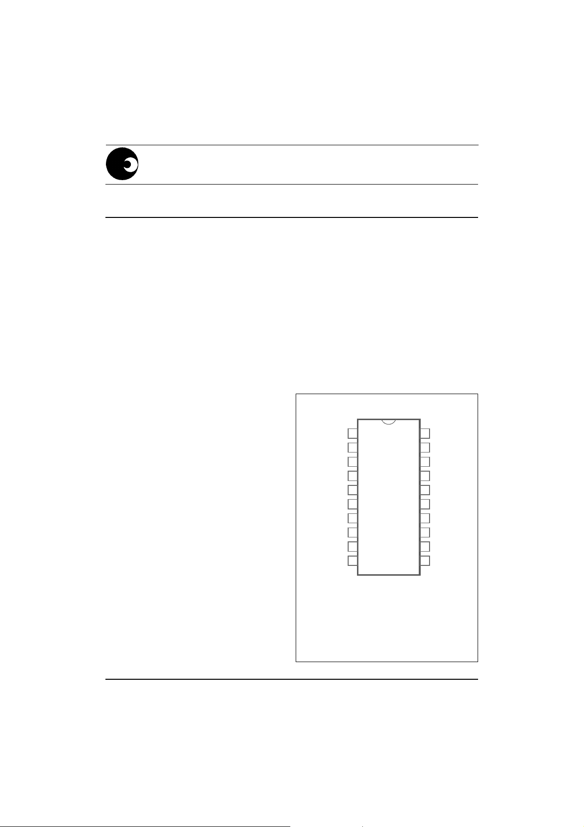
PIN CONNECTIONS
1
2
3
4
5
6
7
8
9
10
DR-00829
Package: DIP-20
SOIC-20
4259
PDS039-SA9103C-001 REV. D 23-08-1996
1/16
SA9103C
INTERFACE
SS
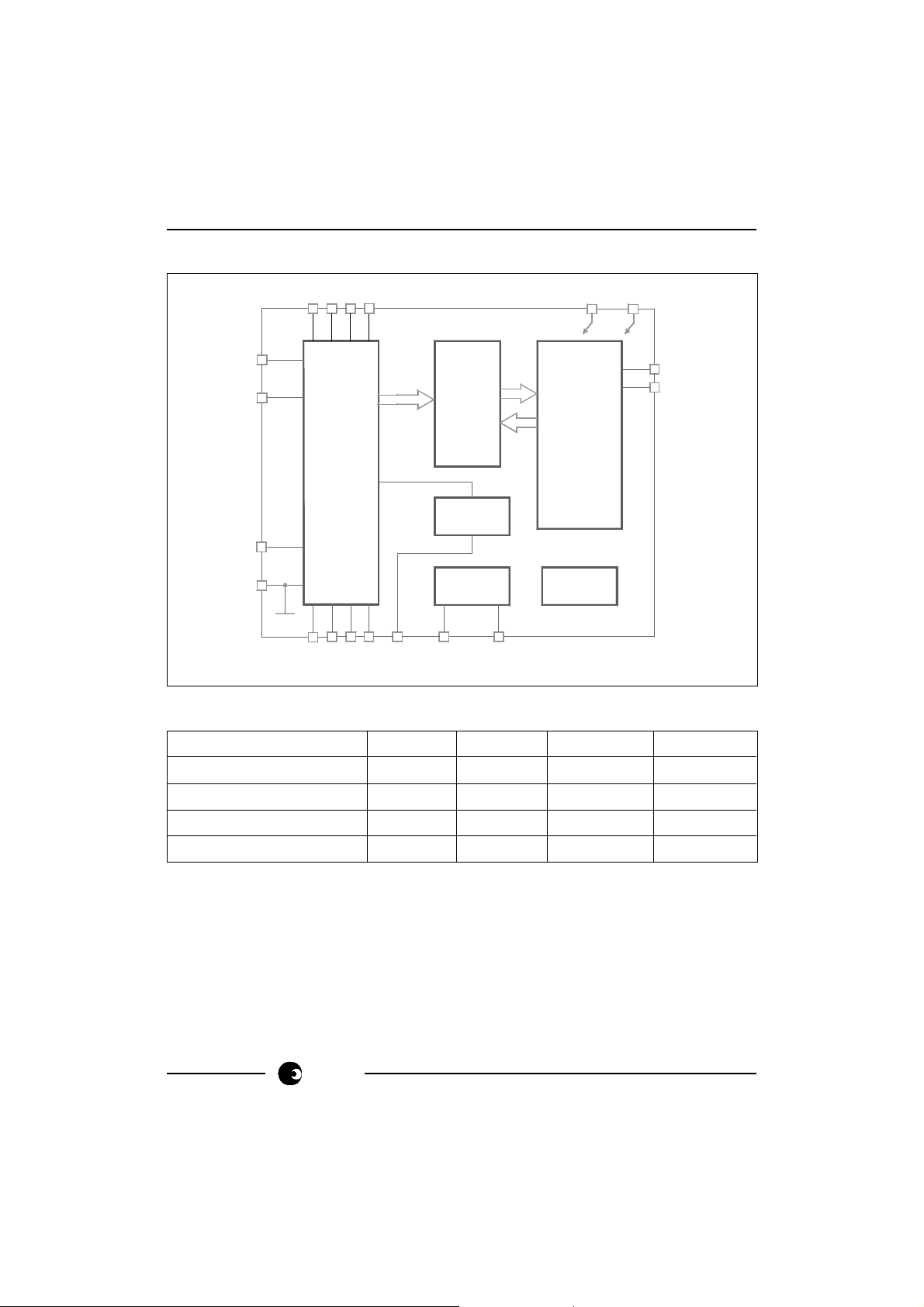
BLOCK DIAGRAM
V
DD
V
IIP
IIN
ANALOG
SIGNAL
ACTIVE
ENERGY
REACTIVE
ENERGY
FREQUENCY
VOLTAGE
SIN
SOUT
SERIAL
PROCE-
VOLTAGE
REF.
OSC
TIMING
OSC2
IVP
GND
DR-00830
SSING
VREF OSC1
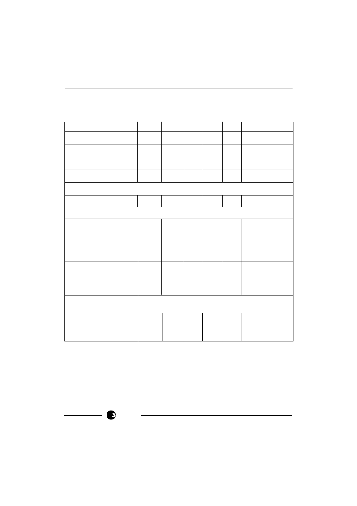
ABSOLUTE MAXIMUM RATINGS*
Parameter Symbol Min Max Unit
Supply Voltage VDD -V
Current on any pin I
Storage Temperature T
Operating Temperature T
PIN
STG
O
SS
-0.3 6.0 V
-150 +150 mA
-40 +125 °C
-10 +70 °C
* Stresses above those listed under “Absolute Maximum Ratings” may cause permanent
damage to the device. This is a stress rating only. Functional operation of the device
at these or any other condition above those indicated in the operational sections of this
specification, is not implied. Exposure to Absolute Maximum Ratings for extended
periods may affect device reliability.
2/16
sames
SA9103C
ELECTRICAL CHARACTERISTICS
(VDD = 2.5V, VSS = -2.5V, over the temperature range -10°C to +70°C#, unless otherwise
specified.)
Parameter Symbol Min Typ Max Unit Condition
Supply Voltage: Positive V
Supply Voltage: Negative V
Supply Current: Positive I
Supply Current: Negative I
2.25 2.75 V
DD
-2.75 -2.25 V
SS
DD
SS
56mA
56mA
Current Sensor Inputs (Differential)
Input Current Range I
-25 +25 µA Peak value
II
Voltage Sensor Input (Asymetrical)
Input Current Range I
IV
-25 +25 µA Peak value
Pin SOUT
Output Low Voltage V
Output High Voltage V
OL
VDD-1 V IOH = -2mA
OH
Pin SIN
Input High Voltage V
Input Low Voltage V
Pull-up Current -I
VDD-1 V
IH
IL
50 150 µA VIN = V
I
Oscillator Recommended crystal:
TV colour burst crystal f = 3.5795 MHz
VSS+1 V IOL = 5mA
VSS+1 V
SS
Pin VREF With R = 24kΩ
Ref. Current -I
Ref. Voltage V
#
Extended Operating Temperature Range available on request.
R
R
sames
45 50 55 µA connected to V
1.1 1.3 V Referred to V
SS
3/16
SS

SA9103C
PIN DESCRIPTION
Pin Designation Description
20 GND Ground
8 V
14 V
DD
SS
Positive Supply Voltage
Negative Supply Voltage
19 IVP Analog input for Voltage
1 IIN Inputs for current sensor
2 IIP
11 OSC1 Connections for crystal or ceramic resonator
10 OSC2 (OSC1 = Input ; OSC2 = Output)
12 SOUT Serial Interface Out
13 SIN Serial Interface In
4 CPON Connections for outer loop capacitors of
5 CPOP A/D converter (Voltage)
6 CPIN Connections for inner loop capacitors of
7 CPIP A/D converter (Voltage)
15 CIP Connections for inner loop capacitors of
16 CIN A/D converter (Current)
17 COP Connections for outer loop capacitors of
18 CON A/D converter (Current)
3 VREF Connection for current setting resistor
9 TP9 Test Pin. Must be connected to V
SS
FUNCTIONAL DESCRIPTION
The SA9103C is a CMOS mixed signal Analog/Digital integrated circuit, which performs
power/energy calculations across a power range of 1000:1, to an overall accurancy of
better than Class 1.
The integrated circuit includes all the required functions for 1-phase power and energy
measurement, such as two oversampling A/D converters for the voltage and current
sense inputs, power calculation and energy integration. Internal offsets are eliminated
through the use of cancellation procedures. The SA9103C integrates the measured
active and reactive power consumption into 22 bit integrators, which are accessable via
a serial port having a RS232 protocol. Two additional on-chip registers exist: one register
contains the mains frequency information; and the other the voltage information.
4/16
sames
1. Power calculation
AVA
In the Application Circuit (Figure 1), the voltage drop across the shunt will be
between 0 and 16mV (0 to 80A through a shunt resistor of 200µΩ). This voltage is
converted to a current of between 0 and 16µA, by means of resistors R1 and R2.
The current sense input saturates at an input current of ±25µA peak.
For the voltage sensor input, the mains voltage (230V AC) is divided down through
a divider to 14V. The resulting current into the A/D converter input is 14µA at
nominal voltage, via resistor R4 (1MΩ).
In this configuration, with a mains voltage of 230V and a current of 80A, the
SA9103C functions at its optimum conditions, having a margin of 3dB for overload
available.
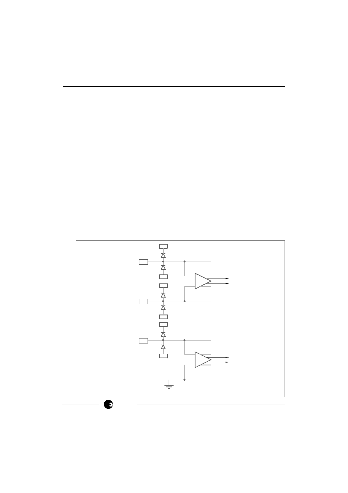
2. Analog Input Configuration
The input circuitry of the current and voltage sensor inputs are illustrated below.
These inputs are protected against electrostatic discharge through clamping
diodes.
The feedback loops from the outputs of the amplifiers AI and AV generate virtual
shorts on the signal inputs. Exact duplications of the input currents are generated
for the analog signal processing circuitry.
V
DD
SA9103C
sames
IIP
CURRENT
SENSOR
INPUTS
IIN
IVP
VOLTAGE
SENSOR
INPUT
DR-00831
V
SS
V
DD
V
SS
V
DD
V
SS
GND
I
5/16
 Loading...