


SAMES SA2007PPA, SA2007PSA Datasheet
Programmable Single Phase Energy Metering
IC with Tamper Detection
SA2007P
FEATURES
+ Provides direct interface to mechanical counters
+ Calibration and setup stored on external EEPROM - no
trimpots required
+ Monitors both Live and Neutral for tamper detection
+ Flexible programmable features
+ Meets the IEC 521/1036 Specification for Class 1 AC Watt
hour meters
DESCRIPTION
The SAMES SA2007P is a single phase bi-directional energy
metering integrated circuit. It provides a cost effective solution
for energy meters with electro-mechanical displays, such as
stepper motors and impulse counters. A precision oscillator,
that replaces an external crystal is integrated on chip.
Two current sensor inputs allow the measurement of energy
consumption on both the live and neutral lines.
Direction detection of energy flow as well as other common
tamper conditions are flagged.
The power consumption on both the live and neutral are
samessames
+ Total power consumption rating below 50mW
+ Adaptable to different types of sensors
+ Operates over a wide temperature range
+ Precision voltage reference on-chip
+ Precision oscillator on chip
continuously measured and the larger of the two is selected for
energy metering.
The SA2007P drives the calibration LED, the indicator LEDs
and the electro-mechanical counter directly.
The SA2007P does not require any external trim-pots. All
required calibration and configuration data is read from a small
external EEPROM.
The SA2007P integrated circuit is available in 20 pin dual-inline plastic (DIP-20) and small outline (SOIC-20) package
types.
SPEC-0074 (REV. 2)
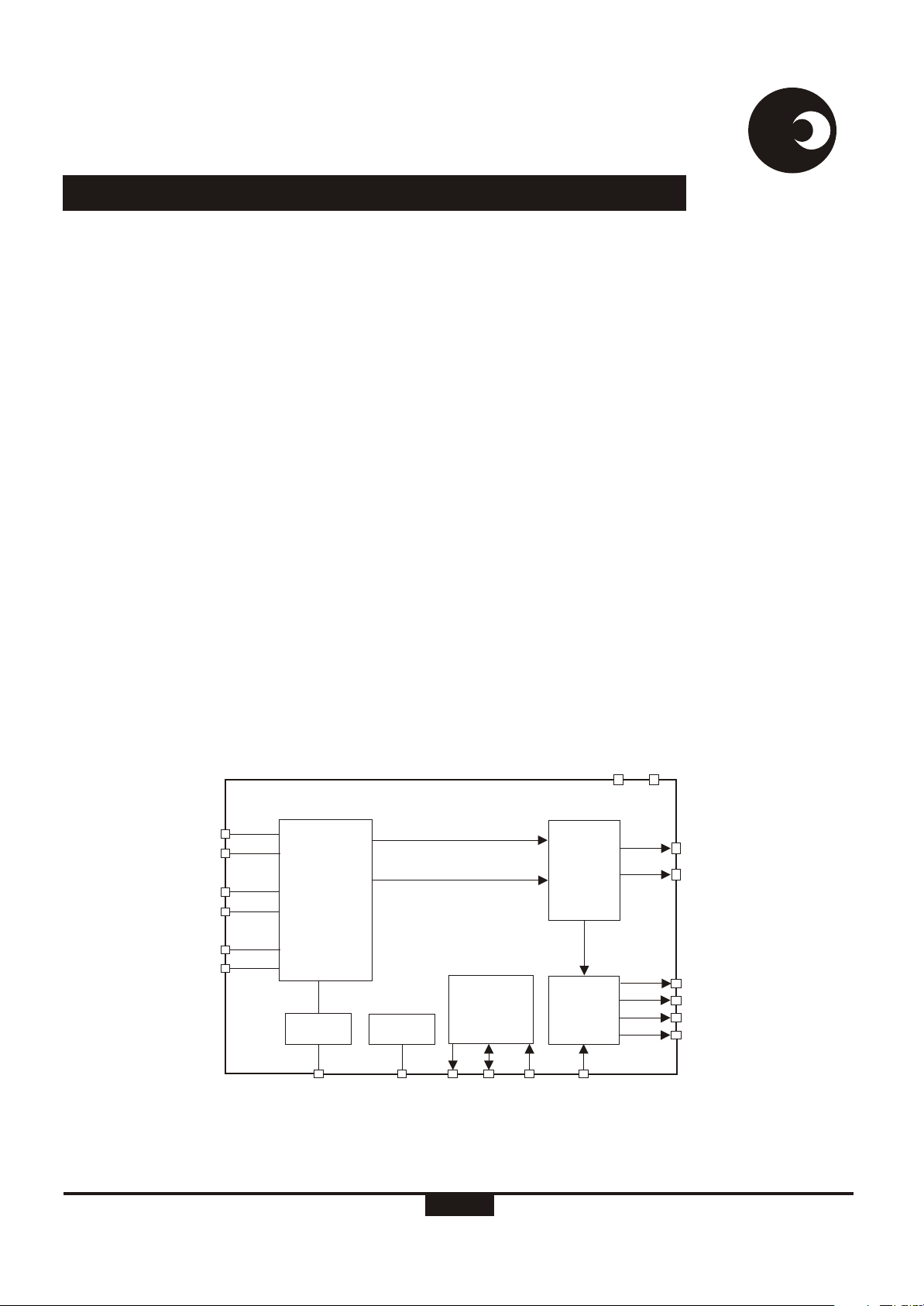
IIN1
IIP1
IIN2
IIP2
IVP
GND
Dr-01594
ANALOG
SIGNAL
PROCESSING
AND
POWER
CALCULATION
VOLTAGE
REF.
VREF
POWER 1 (DIGITAL)
POWER 2 (DIGITAL)
IIC
BUS
OSC
TCLK SDASCL
Figure 1: Block diagram
INTERFACE
RLOAD
1/12
VSSVDD
COM-
PARATOR
POWER
TO
PULSE
RATE
TEST
PRELIMINARY
ELT
SEL1
DIRO
LED
MOP
MON
16-01-01

SA2007P
samessames
ELECTRICAL CHARACTERISTICS
(V = 2.5V, V = -2.5V, over the temperature range -10°C to +70°C , unless otherwise specified.)
DD SS
Parameter
Operating temp. Range
Supply Voltage: Positive
Supply Voltage: Negative
Supply Current: Positive
Supply Current: Negative
Symbol
T
O
V
DD
V
SS
I
DD
I
SS
Min
-25
2.25
-2.75 -2.25
4.7
4.7
#
Typ
Max
+85
2.75
6.6
6.6
9.4
9.4
Current Sensor Inputs (Differential)
Input Current Range
I
II
-25
+25
Voltage Sensor Input (Asymmetrical)
Input Current Range
Pin VREF
Ref. Current
Ref. Voltage
I
IV
-I
R
V
R
-25
45
1.1
50
1.2
+25
55
1.3
Digital I/O
Pins RLOAD, TCLK, TEST, SEL1,
ELT, SDA
Input High Voltage
Input Low Voltage
V
IH
V
IL
V-1
DD
V+1
SS
Pins MOP, MON, LED, SCL, DIRO
V
Output High Voltage
Output Low Voltage
Pin SDA
Pull up current
OH
V
OL
-I
IL
V-1
DD
V+1
24 54
SS
Unit
°C
V
V
mA
mA
µA
µA
µA
V
V
V
V
V
µA
Condition
Peak value
Peak value
With R = 24kW
connected to V
Reference to V
I = -2mA
OH
I = 5mA
OL
V = V
I
SS
SS
SS
Pins TEST, RLOAD, TCLK
Pull down current
I
IH
48 110
µA
V = V
I
DD
# Extended Operating Temperature Range available on request.
ABSOLUTE MAXIMUM RATINGS*
Parameter Symbol Min Max Unit
Supply Voltage V -V -0.3 6.0 V
Current on any pin I -150 +150 mA
Storage Temperature T -40 +125 °C
Operating Temperature T -40 +85 °C
*Stresses above those listed under “Absolute Maximum Ratings” may cause permanent damage to the device. This is a stress
rating only. Functional operation of the device at these or any other condition above those indicated in the operational sections of
this specification, is not implied. Exposure to Absolute Maximum Ratings for extended periods may affect device reliability.
http://www.sames.co.za
DD SS
PIN
STG
O
2/12
PRELIMINARY
SA2007P
PIN DESCRIPTION
Designation Description
PIN
samessames
20
8
14
19
1, 2,
3, 4
5
6
7
9, 12
13
15
GND
V
DD
V
SS
IVP
IIN1, IIP1
IIN2, IIP2
VREF
SCL
SDA
MON, MOP
LED
RLOAD
Analog Ground. The voltage to this pin should be mid-way between V and V .
DD SS
Positive supply voltage. The voltage to this pin is typically +2.5V if a shunt resistor is used for
current sensing or in the case of a current transformer a +5V supply can be applied.
Negative supply voltage. The voltage to this pin is typically -2.5V if a shunt resistor is used for
current sensing or in the case of a current transformer a 0V supply can be applied.
The current into the A/D converter should be set at 14µA at nominal mains voltage. The voltage
RMS
sense input saturates at an input current of ±25µA peak.
Inputs for current sensor - channel 1 and channel 2. The shunt resistor voltage from each channel
is converted to a current of 16µA at rated conditions. The current sense input saturates at an
RMS
input current of ±25µA peak.
This pin provides the connection for the reference current setting resistor. A 24kW resistor
connected to V sets the optimum operating condition.
SS
Serial clock output. This output is used to strobe data from the external EEPROM.
Serial data. Send and receive data from an external EEPROM.
Motor pulse outputs. These outputs can be used to drive an impulse counter or stepper motor directly.
Calibration LED output. Refer to section Led Output (LED) for the pulse rate output options.
Configuration reload input. A falling edge will trigger a register reload from the external EEPROM.
16
17
18
10, 11
SEL1
ELT
DIRO
TEST, TCLK
IIP1 IVP
IIN2 DIRO
IIP2
VREF
SCL
SDA
VDD
MON
Current channel select output. This output indicates which channel is been used for kWh metering.
Earth loop tamper output. This output indicates an earth loop tamper condition.
Direction output. This output indicates the energy flow direction
Test input. Connect to V for normal operation.
1IIN1 GND
2
3
4
5
6 15
7
8
9
10
DR-01595
20
19
18
ELT
17
SEL1
16
RLOAD
VSS
14
LED
13
MOP
12
11
TCLKTEST
SS
Figure 2: Pin connections: Package: DIP-20, SOIC-20
ORDERING INFORMATION
Part Number
SA2007PPA
SA2007PSA
Package
DIP-20
SOIC-20
http://www.sames.co.za
3/12
PRELIMINARY
SA2007P
samessames
FUNCTIONAL DESCRIPTION
The SA2007P is a CMOS mixed signal Analog/Digital
integrated circuit, which performs power/energy calculations
across a power range of 1000:1, to an overall accuracy of
better than Class 1.
The integrated circuit includes all the required functions for
single phase power and energy measurement such as
oversampling A/D converters for the voltage and current sense
inputs, power calculation and energy integration. Internal
offsets are eliminated through the use of cancellation
procedures. The SA2007P incorporates an anti-tamper
scheme by continuously measuring the power consumption on
both LIVE and NEUTRAL lines. A fault is indicated when these
measurements differ by more than 12.5%. The SA2007P
generates pulses with a frequency proportional to the larger of
the two current measurements. The source (LIVE or
NEUTRAL) for these pulses is indicated on the SEL1 pin. The
metering of energy consumption is taken from the source,
which shows the higher consumption.
Various pulse outputs (MOP, MON and LED) are available.
The pulse rate on these pins follows the active power
consumption measured.
A low voltage stepper may be driven directly from the device by
connecting it between the MOP and MON pins, alternatively an
impulse counter may be driven directly by connecting it
between MOP and V .
The SA2007P configures itself from an external low cost
EEPROM that contain all meter configurations and calibration
data. No external trimming is required for this device.
Calibration of the meter may be fully automated.
POWER CALCULATION
In Figure 7, the voltage drops across the current transformers
terminating resistors are converted to currents for each
current sense input, by means of resistors R and R (channel
1) as well as R and R (channel 2). The current sense input
saturates at an input current of ±25µA peak.
SS
10 11
12 13.
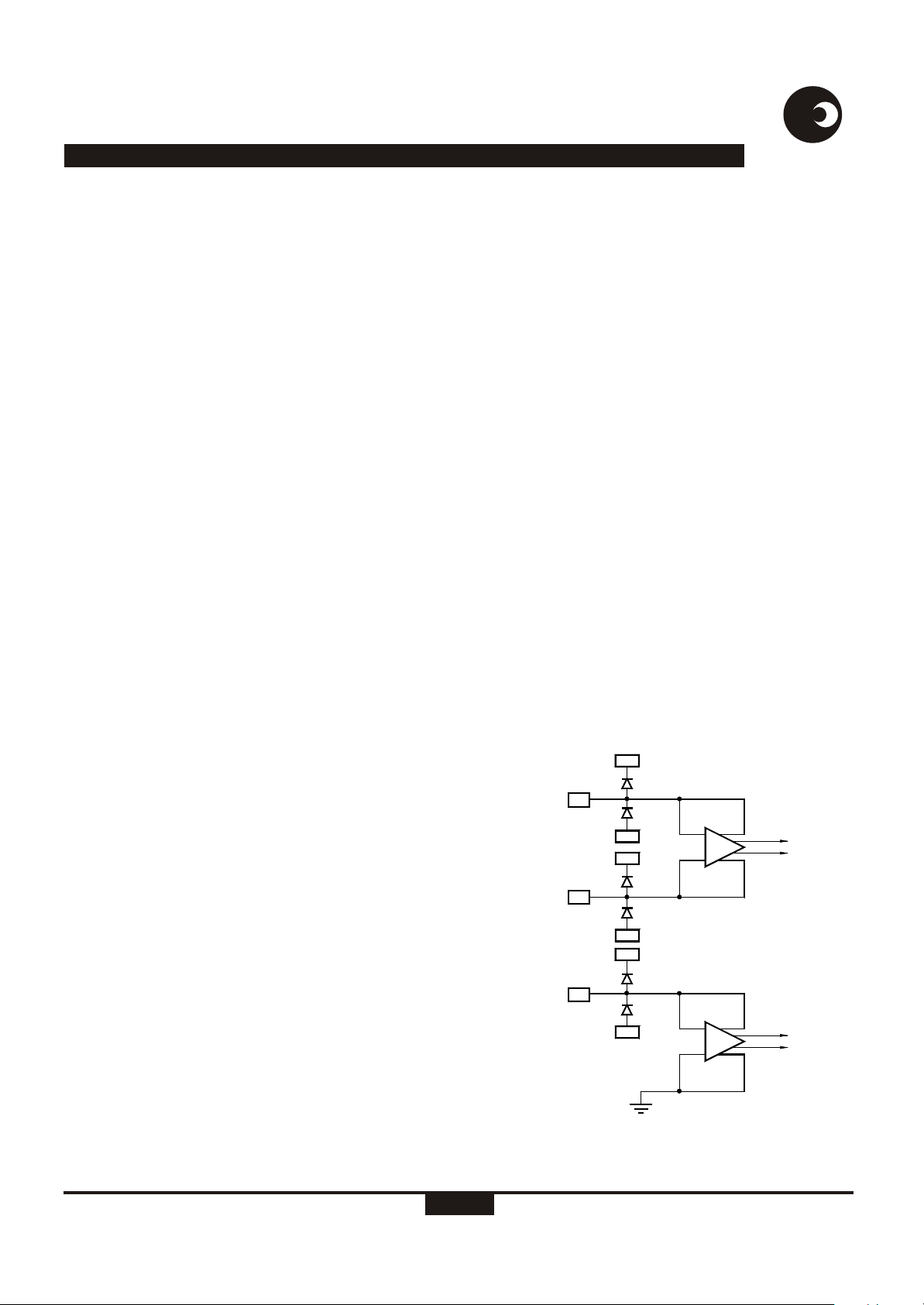
ANALOG INPUT CONFIGURATION
The input circuitry of the current and voltage sensor inputs are
illustrated in figure 3. These inputs are protected against
electrostatic discharge through clamping diodes.
The feedback loops from the outputs of the amplifiers A and A
IV
generate virtual shorts on the signal inputs. Exact duplications
of the input currents are generated for the analog signal
processing circuitry.
AUTOMATIC DEVICE CONFIGURATION (BOOT UP)
During power up, registers containing configuration and
calibration information are updated from an external
EEPROM. The device itself never writes to the EEPROM so
any write protect features offered by manufacturer of
EEPROM's may be used to protect the configuration and
calibration data of the meter. The device reloads its
configuration every 1193 seconds from the external EEPROM
in order to ensure correct operation of the meter. Every data
byte stored in the EEPROM is protected with a checksum byte
to ensure data integrity.
ELECTROSTATIC DISCHARGE (ESD)
PROTECTION
The SA2007P integrated circuit's input's/outputs are protected
against ESD.
POWER CONSUMPTION
The power consumption rating of the SA2007P integrated
circuit is less than 30mW.
V
DD
IIP
V
CURRENT
SENSOR
INPUTS
IIN
SS
V
DD
V
SS
V
DD
A
I
The mains voltage (230VAC) is divided down through a divider
to 14V . The current into the A/D converter input is set at
RMS
14µA at nominal mains voltage, via resistor R (1MW).
RMS 7
See Device Configuration for more details on the processing of
measured energy to frequency outputs.
http://www.sames.co.za
4/12
IVP
VOLTAGE
SENSOR
INPUT
DR-01288
V
SS
GND
A
V
Figure 3: Analog input internal configuration
PRELIMINARY