

SAMES SA2002HPA, SA2002PPA, SA2002PSA Datasheet
Single Phase Bi-directional Power / Energy
Metering IC with Instantaneous Pulse Output
SA2002H
FEATURES
+ Functionally compatible with the SA9602H with reduced
external components
+ Bi-directional power and energy measurement
+ Meets the IEC 521/1036 Specification requirements for
Class 1 AC Watt hour meters
+ Protected against ESD
DESCRIPTION
The SAMES SA2002H is an enhancement of the SA9602H, as
the circuit contains the oscillator on chip.
The SAMES SA2002H single phase bi-directional
power/energy metering integrated circuit generates a pulse
rate output with a frequency proportional to the power
consumption.
The SA2002H performs a calculation for active power. The
method of calculation takes the power factor into account.
Energy consumption can be determined by the power
measurement being integrated over time.
samessames
+ Total power consumption rating below 25mW
+ Adaptable to different types of current sensors
+ Operates over a wide temperature range
+ Precision voltage reference on-chip
+ Precision oscillator on-chip
This innovative universal single-phase power/energy metering
integrated circuit is ideally suited for energy calculations in
applications such as residential municipal metering and factory
energy metering and control.
The SA2002H integrated circuit is available in 8, 14 and 20 pin
dual-in-line plastic (DIP) as well as 16 and 20 pin small outline
(SOIC) package types.
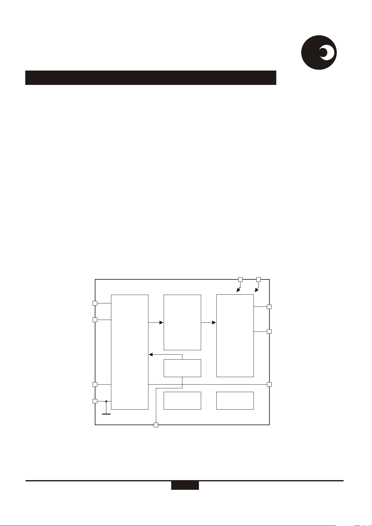
V
V
DD
SS
IIP
IIN
ANALOG
SIGNAL
PROCESSING
IVP
GND
DR-01147
*FMO and DIR not availble in DIP-8 package type
POWER
INTEGRATOR
VOLTAGE
REF.
VREF
Figure 1: Block diagram
POWER
TO
FREQUENCY
TIMINGOSC
FOUT
DIR*
FMO*
SA2002H (REV. 5)
1/12
17-08-00

SA2002H
samessames
ELECTRICAL CHARACTERISTICS
(V = 2.5V, V = -2.5V, over the temperature range -10°C to +70°C , unless otherwise specified.)
DD SS
Parameter
Operating temp. Range
Supply Voltage: Positive
Supply Voltage: Negative
Supply Current: Positive
Supply Current: Negative
Symbol
T
O
V
DD
V
SS
I
DD
I
SS
Min
-25
2.25
-2.75 -2.25
#
Typ
Max
+85
2.75
3
3
5
5
Current Sensor Inputs (Diffferential)
Input Current Range
I
II
-25
+25
Voltage Sensor Input (Asymmetrical)
Input Current Range
Pin FOUT, FMO, DIR
Output High Voltage
Output Low Voltage
Pulse Rate FOUT
Pulse Width FOUT
Pin VREF
Ref. Current
Ref. Voltage
I
IV
V
OL
V
OH
f
p
t
pp
t
pn
-I
R
V
R
-25
V-1
DD
5
0
45
1.1
1360
71.55
143.1
50
+25
V+1
SS
1600
3000
55
1.3
# Extended Operating Temperature Range available on request.
Unit
°C
V
V
mA
mA
µA
µA
V
V
Hz
Hz
Hz
µs
µs
µA
V
Condition
Peak value
Peak value
At rated input conditions
Specified linearity
Min and Max frequency
Positive energy flow
Negative energy flow
With R = 24kW
connected to V
Reference to V
SS
SS
ABSOLUTE MAXIMUM RATINGS*
Parameter Symbol Min Max Unit
Supply Voltage V -V -0.3 6.0 V
Current on any pin I -150 +150 mA
Storage Temperature T -40 +125 °C
Operating Temperature T -25 +85 °C
*Stresses above those listed under “Absolute Maximum Ratings” may cause permanent damage to the device. This is a stress
rating only. Functional operation of the device at these or any other condition above those indicated in the operational sections of
this specification, is not implied. Exposure to Absolute Maximum Ratings for extended periods may affect device reliability.
http://www.sames.co.za
DD SS
PIN
STG
O
2/12
3
SA2002H
PIN DESCRIPTION
8
Pin
8
4
14
Pin
Pin
14 16 20 GND
5 5 8
16
20
Pin
Designation Description
Analog Ground. The voltage to this pin should be mid-way
between V and V .
Positive supply voltage. The voltage to this pin is typically +2.5V
V
DD
if a shunt resistor is used for current sensing or in the case of a
current transformer a +5V supply can be applied.
samessames
DD SS
6
7
1, 2
10
9
13 15 19
1, 2 1, 2 1, 2
3 3 3 3
5
N.A.
N.A.
8 6
9 7
11 11
4 4 4
6 8 5
7 10 6
12 12 7
13
14 10
14
12
13
15
11
16
17
18
Negative supply voltage. The voltage to this pin is typically -2.5V
V
SS
if a shunt resistor is used for current sensing or in the case of a
current transformer a 0V supply can be applied.
Analog Input for Voltage. The current into the A/D converter
IVP
should be set at 14µA at nominal mains voltage. The
RMS
voltage sense input saturates at an input current of ±25µA peak.
Inputs for current sensor. The shunt resistor voltage from each
IIN, IIP
channel is converted to a current of 16µA at rated conditions.
The current sense input saturates at an input current of ±25µA
RMS
peak.
This pin provides the connection for the reference current setting
VREF
resistor. A 24kW resistor connected to V set the optimum
SS
operating condition.
FOUT
DIR
FMO
TP1
Pulse rate output. Refer to pulse output format for a description
of the pulse rate.
Direction output. The direction of the energy flow is indicated on
this output.
Voltage sense zero crossover. The FMO output generates pulses
on energy rising edge of the mains voltage.
Leave pins unconnected.
TP2
TP3
TP4
9
TP5
TP6
TP7
TP8
TP9
TP10
http://www.sames.co.za
3/12
SA2002H
samessames
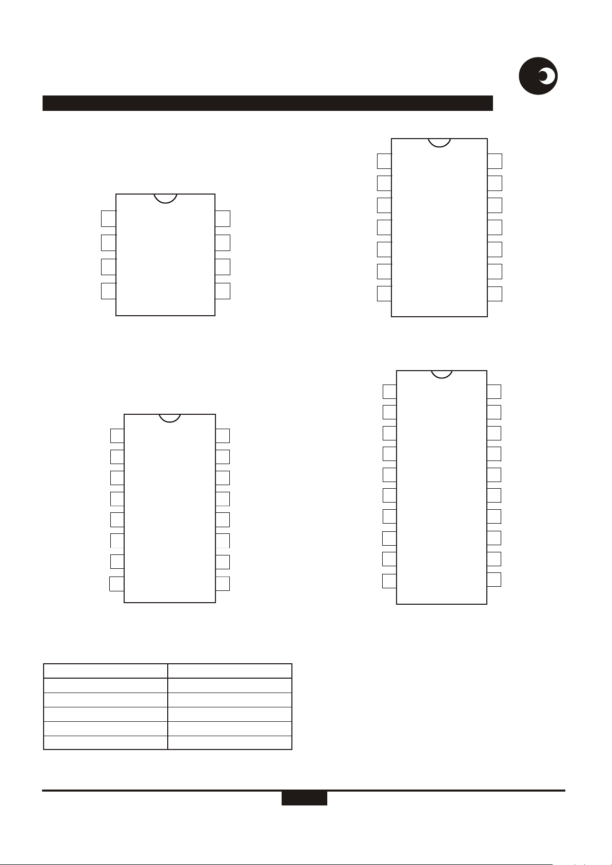
IIN
IIP
VREF
V
1
2
3
4
DD
dr-01487
8
7
6
5
Figure 2: Pin connections: Package: DIP-8
IIN
1
IIP IVP
2
16
15
GND
IVP
V
SS
FOUT
GND
IIN
IIP
VREF
TP1
V
TP2
TP3
1
2
3
4
5
DD
6
7
dr-01488
14
13
12
11
10
9
8
Figure 3: Pin connections: Package: DIP-14
IIN
1
IIP IVP
2
TP1
3
4
VREF
20
19
18
17
GND
IVP
TP4
FMO
V
SS
DIR
FOUT
GND
TP10
TP9
VREF
FOUT
3
4
TP1
5
V
DD
6 11
7
DIR
TP2
8
DR-01489
Figure 4: Pin connections: Package: SOIC-16
ORDERING INFORMATION
Part Number
SA2002HPA
SA2002HPA
SA2002HPA
SA2002HSA
SA2002HSA
Package
DIP-8
DIP-14
DIP-20
SOIC-16
SOIC-20
14
13
12
10
5
TP6
TP5
TP4
FMO
TP3
V
9
SS
TP2
TP3
6 15
7
TP4
V
8
DD
TP5
9
TP6
10
DR-01490
16
14
13
12
11
TP8
FMO
V
SS
DIR
FOUT
TP7
Figure 5: Pin connections: Package: DIP-20, SOIC-20
http://www.sames.co.za
4/12
 Loading...