


SAMES PM9102APA, PM9102APE Datasheet
SA9102 / SA9602 APPLICATION NOTE
sames
PM9102AP
SINGLE PHASE POWER/ENERGY METERING MODULE
PULSE OUTPUT
FEATURES
n Performs both power and energy
measurement
n Total power consumption rating below
500mW (excluding current sensing)
n Meets the accuracy requirements for
Class 1 AC Watt hour meters
n Protected against ESD
n Uses a shunt resistor for current sensing
n Operates over a wide temperature range
DESCRIPTION
The SAMES single phase power/energy metering module, the PM9102AP, provides two
pulse rate output options, the frequency of which are proportional to the active power
consumption.
Energy consumption is determined by the power measurement being integrated over
time.
The method of calculation takes the power factor into account.
The output of this innovative universal power/energy metering circuit is ideally suited for
energy calculations in applications using a µ-controller or mechanical counter.
The application utilises the SAMES SA9102CP, SA9102FP, SA9102HP, SA9602EP
(DIP-20), SA9602HP (DIP-20) or SA9602MP power metering integrated circuits for
power measurement.
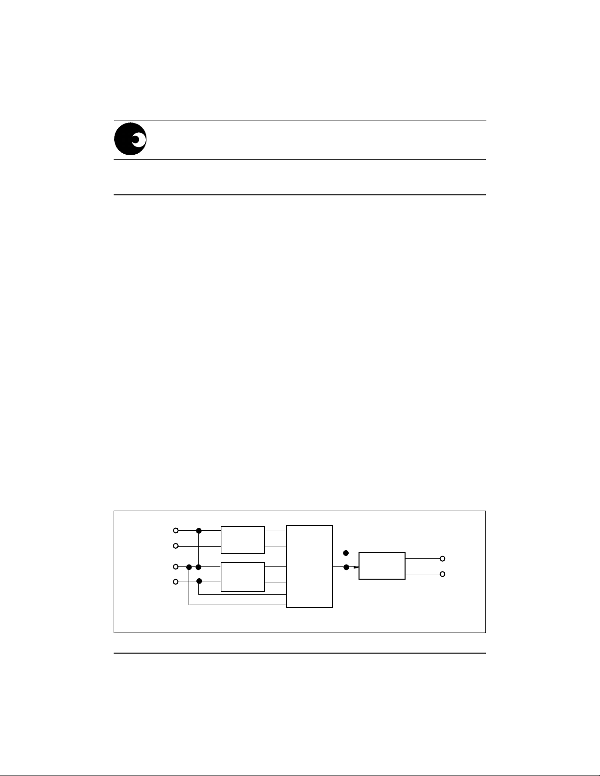
As a safety measure, this application shows the current sensor connected to the neutral
line. In practice, the live line may be used for current sensing, provided that the supply
connections (MAINS) are reversed on the module.
BLOCK DIAGRAM
LIVE
IN
OUT
VOL TAGE SENSE
SHUNT
POWER
SUPPLY
SA9102
SA9602
POWER
METER
DR-01447
OCTO
COUPLER
POWER OUTPUT
NEUTRAL
NEUTRAL
NEUTRAL
4308 PDS038-SA9102-001 REV.C
1/10
06-08-98

PM9102AP
ABSOLUTE MAXIMUM RATINGS*
Parameter Symbol Min Max Unit
Supply Voltage (Note 1) V
Current Sense Input (Note 1) V
Storage Temperature T
Operating Temperature (Note2) T
Max Current
through Sensor
I
I
STG
MAX
MAX
AC
IV
-2.5 +2.5 V
-25 +125 °C
O
-10 +70 °C
540 V
800 (Note 3) A
2000 (Note 4) A
Note 1: Voltages are specified with reference to Live.
Note 2: The SA9102 and SA9602 integrated circuits are specified to operate over the
temperature range -10°C to +70°C. The module functionality will however
depend upon the external components used.
Note 3: t = 500ms
Note 4: t = 1ms
*Stresses above those listed under “Absolute Maximum Ratings” may cause permanent damage
to the device. This is a stress rating only. Functional operation of the device at these or any other
conditions above those indicated in the operational sections of this specification, is not implied.
Exposure to Absolute Maximum Ratings for extended periods may affect device reliability.
ELECTRICAL CHARACTERISTICS
(Over the temperature range -10°C to +70°C, unless otherwise specified. Power
consumption figures are applicable to the PM9102APE only.)
Parameter Symbol Min Typ Max Unit Condition
Supply voltage V
AC
180 230 265 V PM9102APE
(Continuous) 90 115 135 V PM9102APA
Frequency output FOUTX Refer to applicable IC data sheet
Power consumption
1
800 mW VAC = 230V
Supply direct
from mains
200 mW 5VAC supply
Isolation voltage
2
V
IS
2500 V Continuous
Output transistor
collector current I
O
10 mA VOL =1V
Note 1: Power consumption specifications exclude power consumed by the current
sensor.
2/10
sames
PM9102AP
Note 2: Isolation voltage may be specified, depending on customer requirements.
CONNECTION DESCRIPTION
Designation Description
MAINS Voltage supply connection to Neutral line
Voltage supply connection to Live line
Neutral In Connection to positive side of current sensor
Neutral Out Connection to negative side of current sensor
JP1 SA9102/SA9602 output pin selector (Jumper)
SK1 Power measurement output
FUNCTIONAL DESCRIPTION
1. Power Calculation
In the Application Circuit (Figure 2), the output current from the current sensor will
be between 0 and 16µA (0 to 80A through a shunt resistor of 625µS). The current
input stage saturates at input currents greater than18µA
. The mains voltage
RMS
(230V + 15% -20%) is used to supply the circuitry with power and for the power
calculation, together with the current information from the current sensor (shunt
resistor).
The SA9102CP, SA9602EP (DIP-20), SA9602HP (DIP-20) and SA9602MP
integrated circuits may be adjusted to accommodate any voltage or current values.
The method of calculating external component values is described in paragraph 5
(Circuit Description).
SAMES offers evaluation module options, namely 230V/80A and 115V/80A.
The calculated power is integrated over time and converted into a corresponding
frequency. The frequency is transmitted as a pulse rate through an opto-coupler.
2. Electrostatic Discharge (ESD) Protection
The device's inputs/outputs are protected against ESD according to Mil-Std 883C,
method 3015. The modules resistance to transients will be dependant upon the
protection components used.
3. Power Consumption
The overall power consumption rating for this power metering application (Figure
2), is under 500mW, excluding the current sensor, if a supply is taken directly from
the mains.
4. Isolation
The pulse output is isolated from the module, which is at mains potential, via an
opto-coupler. (In the event of the use of a current transformer for current sensing,
an opto-coupler would not be required.)
sames
3/10