

Page 1

Index revision: C - March 2016 1 7105
User manual
SAS SAMES Technologies. 13 Chemin de Malacher -
Inovallée - CS 70086 - 38243 Meylan Cedex France
Tel. 33 (0)4 76 41 60 60 - Fax. 33 (0)4 76 41 60 90 - www.sames.com
NANOGUN-MV and GNM 6080
versions LR - HR
Page 2

Index revision : C - March 2016 2 7105
This document may not be passed on or reproduced in any form whatsoever nor may its contents be
used or disclosed without express written permission from SAMES Technologies.
The descriptions and characteristics contained in this document are subject to change without notice.
© SAMES Technologies 2014
WARNING : SAS Sames Technologies is registered with the Ministry of Labour as a training
institution.
Throughout the year, our company offers training courses in the operation and
maintenance of your equipment.
A catalogue is available on request. Choose from a wide range of courses to
acquire the skills or knowledge that is required to match your production
requirements and objectives.
Our training courses can be delivered at your site or in the training centre at our
Meylan head office.
Training Department:
Tel.: 33 (0)4 76 41 60 04
E-mail : [email protected]
SAS Sames Technologies user manuals are written in French and translated into English, German, Spanish, Italian and Portu-
guese.
The French version is deemed the official text and Sames will not be liable for the translations into other language
Page 3

Index revision : 3
NANOGUN-MV and GNM 6080
versions LR - HR
1. Product identification - - - - - - - - - - - - - - - - - - - - - - - - - - - - - - - - - - - 6
1.1. Identifying the version . . . . . . . . . . . . . . . . . . . . . . . . . . . . . . . . 6
1.1.1. By the barrel. . . . . . . . . . . . . . . . . . . . . . . . . . . . . . . . . . . . . . . . . 6
1.1.2. By the base support. . . . . . . . . . . . . . . . . . . . . . . . . . . . . . . . . . . 6
1.2. GNM 6080 control module . . . . . . . . . . . . . . . . . . . . . . . . . . . . . 7
2. Health and Safety Instructions - - - - - - - - - - - - - - - - - - - - - - - - - - - - 8
2.1. Regulations . . . . . . . . . . . . . . . . . . . . . . . . . . . . . . . . . . . . . . . . 8
2.2. Installation rules . . . . . . . . . . . . . . . . . . . . . . . . . . . . . . . . . . . . . 8
2.3. Operating rules . . . . . . . . . . . . . . . . . . . . . . . . . . . . . . . . . . . . . 9
2.4. Maintenance rules . . . . . . . . . . . . . . . . . . . . . . . . . . . . . . . . . . 10
2.4.1. Products used . . . . . . . . . . . . . . . . . . . . . . . . . . . . . . . . . . . . . . 11
3. Description of spray gun and GNM 6080 control module- - - - - - - - - 12
3.1. Functions available on spray gun . . . . . . . . . . . . . . . . . . . . . . 12
3.2. GNM 6080 Control module . . . . . . . . . . . . . . . . . . . . . . . . . . . 13
4. Technical characteristics - - - - - - - - - - - - - - - - - - - - - - - - - - - - - - - 15
4.1. General spray gun characteristics . . . . . . . . . . . . . . . . . . . . . 15
4.2. GNM 6080 Characteristics . . . . . . . . . . . . . . . . . . . . . . . . . . . 16
4.3. Compressed air characteristics . . . . . . . . . . . . . . . . . . . . . . . . 16
5. Operation - - - - - - - - - - - - - - - - - - - - - - - - - - - - - - - - - - - - - - - - - - 17
6. Special tools- - - - - - - - - - - - - - - - - - - - - - - - - - - - - - - - - - - - - - - - 18
6.1. Using the multipurpose spanner . . . . . . . . . . . . . . . . . . . . . . . 20
7. Installation - - - - - - - - - - - - - - - - - - - - - - - - - - - - - - - - - - - - - - - - - 21
7.1. With piston pump for all versions . . . . . . . . . . . . . . . . . . . . . . . 21
7.2. With diaphragm pump for all versions . . . . . . . . . . . . . . . . . . . 22
7.3. With a pressure tank for all versions . . . . . . . . . . . . . . . . . . . . 23
8. Operation - - - - - - - - - - - - - - - - - - - - - - - - - - - - - - - - - - - - - - - - - - 24
8.1. Paint Recommendations . . . . . . . . . . . . . . . . . . . . . . . . . . . . . 24
8.1.1. Viscosity. . . . . . . . . . . . . . . . . . . . . . . . . . . . . . . . . . . . . . . . . . . 24
8.1.2. Resistivity. . . . . . . . . . . . . . . . . . . . . . . . . . . . . . . . . . . . . . . . . . 24
8.1.3. Flash point . . . . . . . . . . . . . . . . . . . . . . . . . . . . . . . . . . . . . . . . 24
8.2. Settings of the spraying parameters . . . . . . . . . . . . . . . . . . . . 25
9. Misuse of the Apparatus - - - - - - - - - - - - - - - - - - - - - - - - - - - - - - - 28
10. Maintenance- - - - - - - - - - - - - - - - - - - - - - - - - - - - - - - - - - - - - - - 29
10.1. Preventive maintenance table . . . . . . . . . . . . . . . . . . . . . . . . 29
10.2. Electropneumatic coupling . . . . . . . . . . . . . . . . . . . . . . . . . . 30
10.3. Paint Hoses . . . . . . . . . . . . . . . . . . . . . . . . . . . . . . . . . . . . . . 31
10.3.1. Paint hose - QD version (HR) . . . . . . . . . . . . . . . . . . . . . . . . . 31
10.3.2. Paint hose LR . . . . . . . . . . . . . . . . . . . . . . . . . . . . . . . . . . . . . 32
10.4. Spray head assembly . . . . . . . . . . . . . . . . . . . . . . . . . . . . . . 33
Page 4

Index revision : 4
10.5. Barrel . . . . . . . . . . . . . . . . . . . . . . . . . . . . . . . . . . . . . . . . . . . 34
10.6. Paint needle . . . . . . . . . . . . . . . . . . . . . . . . . . . . . . . . . . . . . . 35
10.7. Switch . . . . . . . . . . . . . . . . . . . . . . . . . . . . . . . . . . . . . . . . . . 35
10.8. Trigger . . . . . . . . . . . . . . . . . . . . . . . . . . . . . . . . . . . . . . . . . . 36
10.9. Air valve . . . . . . . . . . . . . . . . . . . . . . . . . . . . . . . . . . . . . . . . . 36
10.9.1. Repairing the air valve. . . . . . . . . . . . . . . . . . . . . . . . . . . . . . . 37
10.10. Fixing hook . . . . . . . . . . . . . . . . . . . . . . . . . . . . . . . . . . . . . 38
10.11. High voltage cascade . . . . . . . . . . . . . . . . . . . . . . . . . . . . . 39
10.12. Barrel . . . . . . . . . . . . . . . . . . . . . . . . . . . . . . . . . . . . . . . . . . 40
10.13. Handle . . . . . . . . . . . . . . . . . . . . . . . . . . . . . . . . . . . . . . . . . 41
10.14. Electric diagrams . . . . . . . . . . . . . . . . . . . . . . . . . . . . . . . . . 42
10.14.1. Connection cable GNM 6080 / NANOGUN-MV. . . . . . . . . . . 42
10.14.2. GNM 6080 trigger cable. . . . . . . . . . . . . . . . . . . . . . . . . . . . . 42
11. Cleaning- - - - - - - - - - - - - - - - - - - - - - - - - - - - - - - - - - - - - - - - - - 43
11.1. Cleaning the product circuit . . . . . . . . . . . . . . . . . . . . . . . . . . 43
11.2. Cleaning the spray gun . . . . . . . . . . . . . . . . . . . . . . . . . . . . . 43
11.3. Waste disposal . . . . . . . . . . . . . . . . . . . . . . . . . . . . . . . . . . . 43
11.4. Demolition and Recycling . . . . . . . . . . . . . . . . . . . . . . . . . . . 44
11.4.1. NANOGUN-MV . . . . . . . . . . . . . . . . . . . . . . . . . . . . . . . . . . . . 44
11.4.2. GNM 6080 . . . . . . . . . . . . . . . . . . . . . . . . . . . . . . . . . . . . . . . . 46
12. Troubleshooting Guide- - - - - - - - - - - - - - - - - - - - - - - - - - - - - - - - 47
13. Spare Parts - - - - - - - - - - - - - - - - - - - - - - - - - - - - - - - - - - - - - - - 49
13.1. NANOGUN-MV spray guns low pressure for high resistivity
(HR) solvent paint ρ > 10MΩ.cm . . . . . . . . . . . . . . . . . . . . . . . . . . 49
13.2. NANOGUN-MV, low Pressure spray guns for solvent paint
0.5 MΩ.cm < ρ < 500 MΩ.cm . . . . . . . . . . . . . . . . . . . . . . . . . . . . . 51
13.3. NANOGUN-MV spray guns, all versions . . . . . . . . . . . . . . . . 52
13.4. Barrel assembly . . . . . . . . . . . . . . . . . . . . . . . . . . . . . . . . . . . 54
13.5. Air valve and Nut air valve . . . . . . . . . . . . . . . . . . . . . . . . . . . 55
13.6. Air cap ring . . . . . . . . . . . . . . . . . . . . . . . . . . . . . . . . . . . . . . 56
13.7. Nozzle support . . . . . . . . . . . . . . . . . . . . . . . . . . . . . . . . . . . . 56
13.8. Round Nozzle assemblies - LP Models . . . . . . . . . . . . . . . . . 57
13.9. Needle assembly . . . . . . . . . . . . . . . . . . . . . . . . . . . . . . . . . . 58
13.10. Electropneumatic coupling sets . . . . . . . . . . . . . . . . . . . . . . 58
13.11. Paint hoses . . . . . . . . . . . . . . . . . . . . . . . . . . . . . . . . . . . . . 59
13.11.1. For NANOGUN-MV Low Pressure and High Resistivity
spray guns . . . . . . . . . . . . . . . . . . . . . . . . . . . . . . . . . . . . . . . . . . . . . . 59
13.11.2. For NANOGUN-MV Low Pressure and Low Resistivity
spray guns . . . . . . . . . . . . . . . . . . . . . . . . . . . . . . . . . . . . . . . . . . . . . . 59
13.12. GNM 6080 Control module . . . . . . . . . . . . . . . . . . . . . . . . . 60
13.13. Options for NANOGUN-MV Low Pressure spray guns . . . . 61
13.13.1. Fan Spray Air Caps . . . . . . . . . . . . . . . . . . . . . . . . . . . . . . . . 61
13.13.2. In-line product filters. . . . . . . . . . . . . . . . . . . . . . . . . . . . . . . . 61
13.14. Appendices . . . . . . . . . . . . . . . . . . . . . . . . . . . . . . . . . . . . . 62
13.14.1. Protective hose covering . . . . . . . . . . . . . . . . . . . . . . . . . . . . 62
13.14.2. Protective case for spray gun . . . . . . . . . . . . . . . . . . . . . . . . 62
Page 5

Index revision : 5
13.14.3. Warning notice. . . . . . . . . . . . . . . . . . . . . . . . . . . . . . . . . . . . 62
13.14.4. Safety valve . . . . . . . . . . . . . . . . . . . . . . . . . . . . . . . . . . . . . . 62
14. The different versions - - - - - - - - - - - - - - - - - - - - - - - - - - - - - - - - 63
14.1. Equipments . . . . . . . . . . . . . . . . . . . . . . . . . . . . . . . . . . . . . . 63
14.2. Configuration . . . . . . . . . . . . . . . . . . . . . . . . . . . . . . . . . . . . . 64
Page 6

Index revision : C - March 2016 6 7105
1. Product identification
The various markings on NANOGUN-MV spray guns can be used to identify whether low pressure (LP)
configuration is being used.
1.1. Identifying the version
1.1.1. By the barrel
All NANOGUN-MV range products carry the same markings on the barrel.
1.1.2. By the base support
This marking groups together all spray gun configurations ope rating at the same product p ressure under
the same number.
Marking no. Product pressure NANOGUN-MV models
910015741 7 bar
JR06-LR; JR06-HR
JR08-LR; JR08-HR
JR12-LR; JR12-HR
JP-LR; JP-HR
DES05881
P max
7 bar / 101 psi
Page 7

Index revision : C - March 2016 7 7105
1.2. GNM 6080 control module
The GNM 6080 control module should not be installed in an ATEX zone (potentially explosive
atmosphere). It is defined as “associated material” for the purposes of the ATEX directive.
Markings
Example: * 2014: Year of manufacturing
26: Week number
123: Nth control module made in the week 26.
WARNING : Equipment Nanogun is in accordance with the functional safety standard (Standard
EN13849, level SIL 1), the preservation of this level of safety imposes a periodic control of the
equipment, in minima every 5 years or 15000 hours of functioning (to the first one 2 reached).
This control concerns each of the electric and electronic components as well as on it or the very
specific programs, you have to get in contact with your subsidiary, distributor or usual representative of Sames
Technologies who will indicate you the steps to be carry out.
DES05878
DES05879
Version Software:
S/ N :
Version Software:
S/ N :
2014 26123 *
2014 26123 *
CE Marking
CSA
Marking
Page 8

Index revision : C - March 2016 8 7105
2. Health and Safety Instructions
WARNING : This equipment may become a safety hazard if it is not operated, disassembled and
reassembled in accordance with the instructions given in this manual and in any
European Standard or national safety regulations in force.
The warning notice summarizing the safety rules (p rocedures and precautions) laid
out in this instruction manual must be clearly dis played in the area of t he spray ing
workstation.
WARNING : Equipment performance is only guaranteed if original spare parts distributed by
SAMES Technologies are used.
2.1. Regulations
The NANOGUN-MV spray gun must always be used according to the requirements stipulated in the
standards and regulations in force concerning painting and clear coat methods (see Standards and
Directives EN 50.053 part 1 ISO 12100, EN 1953 and 99/92/CE).
In Canada, the installation has to be in compliance with the code " electrica l C22.1 Canadia n code, part
I, standard safety for electrical installations ".
In the USA, the installation has to be in compliance with the code " NFPA 70: National Electrical Code ".
The Pollution Degree Rating of the NANOGUN-MV is ”Pollution Degree 2” following IEC-664-1 standa rd
Pollution Degree 2: Normally only non-conductive pollution occurs. Temporary conductivity caused by
condensation is to be expected.
WARNING : Before any use of the NANOGUN-MV spray gun, check that all operators
• have previously been trained by the company Sames Technologies, or by their distributors
registered by them for this purpose.
• have read and understood the user manual and all rules for installation and operation, as listed
below.
It is the responsibility of the operator’s workshop manager to ensure these two points and it is
also his responsibility to make sure that all operators have read and understood the user
manuals for any peripheral electrical equipment present in the spraying area.
2.2. Installation rules
• The manual projection electrostatic material must be used on ly in proje ction ar ea accor ding to the
standard EN 12215 or in equivalent conditions of ventilation.
• The control module must not be installed where there is a potential explosion risk.
• It must be impossible to start up the control module before the spray booth air extraction system
is in operation.
• The control module must be properly connected to the ground terminal on the device.
• The paint (or solvent) pump and tank must be connected to a ground terminal on the device.
• All metal parts of the apparatus (paint pumps, containers, stools, turntables, etc.) less than three
metres from the spray gun must be grounded.
• The spraying area must be kept clean and clear of any unnecessary items.
Page 9

Index revision : C - March 2016 9 7105
• The floor on which the operator works must be dissipator (bare concrete or metal duckboard).
Never use an insulating floor covering. In area potentially explosive, the assemblies of grounds
have to be dissipators according to the standard EN 61340-4-1.
• Naked flames, glowing objects or a devices likely to produce sparks (o ther than the atomizer) must
not be used inside the booth.
The storage of inflammable pro ducts, or ves sels that have contained th em, close t o the booth or
in front of the doors is prohibited.
• Pots and tubs containing paint or solvent must always be closed after use.
• The paint supply pump used must have a maximum ratio of 1:1 and the pump air supply must be
fitted with a safety valve limiting the pressure to 6.5 bar maximum.
• In the explosive area, it is forbidden to use any non-certified electrical or non-electrical equipment
such as electronic extension leads, multiple socket adap te r s, switches, etc.
2.3. Operating rules
• The ventilation system must be checked on a daily basis to ensure it is working properly.
• Performance checks must be carried out on the extraction control system once a week.
•
Before starting to spray, check that the nozzle/tip and air cap are fitted to the gun and that the air cap
ring is fully tightened.
• All metal parts of the booth and parts to be painted must be correctly grounded. Ground resistance
must be less than or equal to 1MΩ (measurement voltage 500 V). This resistance value must be
regularly checked.
• The operator must wear dissipator shoes according Standard EN 61340-4-3 and hold the
NANOGUN-MV spray gun bare-handed or with gloves that are either dissipators or specially
adapted to allow direct contact between the handle and the operator’s hand. Shoes intended to be
worn by the operator have to be in accordance with the standard ISO 20344. The measured
insulating resistance does not have to exceed 100MΩ.
• Protective clothings intended to be worn, including gloves, have to be in accordance with the
standard EN 1149-5. The measured insulating resistance does not have to exceed 100MΩ.
• The operator must also wear ear defenders when using NANOGUN-MV spray guns ( see § 4 page
15).
• Ensure that anyone who enters the spraying area is wearing dissipator shoes or is otherwise
grounded.
• Never throw or drop deliberately the electrostatic spray gun. Dropping the gun could damage the
high voltage generator. After a drop, it is advised to verify the functioning of the pistol out off zone
before its re-use.
• Never point the spray gun towards a person.
• Check the spray gun at least 1 time a week.
• Never use the apparatus in the following situa tion s:
1 If you notice an air leak from the spray gun when the trigger is released.
2 If the spray gun electrical connector catch is not held securely in place with two safety screws.
3 If the spray gun barrel, handle show signs of an impact that may have deteriorated the air-
tightness of internal components.
• The manual electrostatic projection equipment must be exploited only if it is in a perfect state. A
damaged equipment must be immediately removed from the installation and must be repaired.
The worn out components must be immediately replaced.
• Use paints whose flash point is at least 15°C higher than the ambient temperature.
• Follow the precautions specified for the paints and solvents used (e.g. wear a mask etc.).
• Close and dump the air and paint supply before leaving the device shut down for an extended
period.
• Check the paint hose is in good condition before starting to operate the device.
• The electropneumatic coupling, held in place by two safety screws
MUST NEVER BE
DISCONNECTED IN A POTENTIALLY EXPLOSIVE ATMOSPHERE.
• If any of the following elements are damaged, all operations with the device must be stopped:
barrel, handle, electropneumatic coupling, air cap or air cap ring.
Page 10

Index revision : C - March 2016 10 7105
2.4. Maintenance rules
• Service regularly and repaire the electrostatic spraying equipment in accordance with the
instructions in this user manual.
• Metal containers only should be used to hold cleaning liquids and they must have a reliable ground
connection.
• Before any maintenance or servicing operation:
1 Disconnect the control module from the power supply.
2 Check that the air and paint circuits are not pressurized.
3 Dump the paint Circuit
4 All the energy sources must be consigned.
• Cleaning operations must be carried out either in authorised areas equipped with a mechanical
ventilation system, or using cleaning liquids with a flash point at least 15 °C higher than the ambient
temperature.
• Use non flammable cleaning products preferably.
• Do not reconnect the electrical power supply until the air cap and nozzle/tip have been correctly
reassembled on the spray gun.
• Never soak or immerse the spray gun in solvent. If required, the spray gun may be cleaned by
wiping with a cloth soaked in solvent and then immediately dried to prevent the solvent entering
the spray gun.
WARNING : Never spray solvent whilst the control module is live and/or the switch located on
the back of the gun is in position «I».
WARNING : The cut of the compressed air supply does not prohibit the release of the high
voltage when the trigger is activate.
• Operators must be trained by Sa me s T ech n olo g ies, or by their distributors registered by them for
this purpose, to perform NANOGUN-MV spray gun maintenance operations.
WARNING : It is forbidden to use oil-based solvent and products containing such solvents if
aluminium or zinc are present. Users who do not follow these instructions are
exposed to explosion risks.
Page 11

Index revision : C - March 2016 11 7105
2.4.1. Products used
Given the wide range of products used, and that fact that it is impossible to prod uce an inventory of these
products, Sames Technologies cannot be held liable for:
• incompatibility of product material used when in contact with materials listed below:
• Stainless steel
• Fluoroethylenepropylene (FEP)
• Polyamide-imide (PAI)
• Polyoxymethylene (POM)
• Tungsten carbide and Tungsten
•PTFE elastomer
• Polypropylene
• IXEF
• Glass fibre
• Ceramics
•Aluminium
• Titanium
• PEEK
• PEHD andPEBD
• Chemically inert rubber
• Risks related to the use of these products for personnel and the environment inclu de.
• Wear, incorrect adjustments or malfunction of equipment or machines, together with the nonquality of the application caused by the use of these products.
Page 12

Index revision : C - March 2016 12 7105
3. Description of spray gun and GNM 6080 control module
NANOGUN-MV spray guns are designed to spray paint or clear coat whose resistivity is greater than
0.5 MΩ.cm only.
The configurations LR can moreover spray hydrodiluable paints or clear coats when th ey are eq uipped
with the suitable produced means of supply. The use of any other type of paint is excluded.
NANOGUN-MV spray guns are to be connected to the GNM 6080 control module.
The models in the NANOGUN-MV range can be differentiated by their air cap, air cap ring, the base
support and the paint hose.
3.1. Functions available on spray gun
• The switch (Item1) allows to start or to cut the high voltage.
When this switch is on the position " I ", an action on the trigger starts up the high voltage.
When this switch is on the position " 0 ", an action on the trigger does not start the high voltage.
• The notched button on the back of the gun (Item 2) allows to regulate the product flow.
• The side notched button (Item 3) allows to regulate the dimension of the spray.
Characteristics
NANOGUN-MV JR06
Super Vortex Round Spray - Low Pressure - Dia: 6
mm
NANOGUN-MV JR08
Super Vortex Round Spray - Low Pressure - Dia: 8
mm
NANOGUN-MV JR12
Super Vortex Round Spray - Low Pressure - Dia: 12
mm
NANOGUN-MV JP Flat Spray - Low Pressure - Dia : 12 mm
1
2
3
Page 13

Index revision : C - March 2016 13 7105
3.2. GNM 6080 Control module
The GNM 6080 control module allows the display of the parameters of use as well as their adjustments.
Temperature fault : The temperature fault forces the indicator lights (Item11 and 12). As
soon as the temperature decrease under the minimum, the temperature in dicator light (Item
11) goes out and the operator can delete the fault by pre ssing on the button «Reset of faults»
(Item 3).
Control module fault: this fault collects all the internal faults of the control module. If this
fault can not resetted, the problem requires the intervention of the repair department , contact
Sames Technologies.
1 Maintenance indicator light
2 Indicator light of high voltage fault
3 Reset of faults
4 Display of setpoint of high voltage
5 Increase of the setpoint voltage
6 Bargraph of the current consumption
7 Indicator lights of active preset memory
8 Selection of the active memory
9 Bargraph of the voltage
10 Decrease of the setpoint voltage
11 Indicator light of temperature fault
12 Indicator light of control module fault
13 Indicator light of low voltage cable
Front face of the GNM 6080 control module
12
4
3
5
6
7
8
9
10
11
12 13
Page 14

Index revision : C - March 2016 14 7105
Low voltage connection fault: the control module does not detect or any more the
presence of the gun. Switch off the main power supply, check the connection between the
control module and the gun.
High voltage faults: faults specific to the operation of the gun related to the high voltage:
• Startup of the control module with the engaged trigger.
• Peak of an important over-current during the high voltage.
• Bad functioning of the high voltage unit.
Maintenance indicator light: This indicator light ig nites (orange) from 80000 0 operations of
the trigger or at the 1000 hours of functioning of th e gu n (see § 10.1 page 29
).
The ignition of this light indicates that the maintenance of the gun must be carried out. No
specific maintenance on the GNM 6080.
The control module can manage up to 20 different guns.
12 Plug for gun cable
13 Plug for external cablings
14 Switch ON / OFF
15 Main power supply
16 Ground connection
17 Diaphragm of pressure balancing
18 Diagnosis plug (type mini USB)
Side face of the GNM 6080 control module
12
13
15
14
161718
Page 15

Index revision : C - March 2016 15 7105
4. Technical characteristics
4.1. General spray gun characteristics
(*)
The weighted equivalent continuous sound pressure level is between 93.8 et 98.6dBA, depending on spray gun version.
Measurement conditions:
The apparatus was operated to maximum capacity and the measurements
taken in the manual paint test booth (sealed booth with glass panels) located in the Sames site in Meylan, France.
Measurement method:
The weighted equivalent sound pressure l evel ( 93.8 et 98.6 dBA) is an LEQ value measured during observation
periods over at least 30 seconds.
JR06 JR08 JR12 JP
Spray type
Round Super
Vortex
Round Super
Vortex
Round Super
Vortex
Fan spray
Air cap fitted as standard JR06 JR08 JR12 P15
Max. paint intake pressure 7 bar 7 bar 7 bar 7 bar
Compressed-air intake pressure
6 bar ± 1 bar
Mini/ maxi ambient temperature
0°C - 40°C
Max. paint flow rate (paint viscosity 25s when
measured with AFNOR Cup 4) in cm
3
/min
650 650 750 750
Spray width, 25 cm away 19 cm 20 cm 21 cm 37 cm
Air flow rate Nm
3
/h
6.6 - 16.8 7.8 - 16.8 9.4 - 22.5 10,3 - 25,2
Sound pressure (*)
93.8 dB(A) 93.8 dB(A) 93.8 dB(A) 98.6 dB(A)
Recommended paint viscosity (measured with
AFNOR Cup 4)
14 to 50 s
Dimensions 273 x 220 x 52
Weight without hoses or cables 570 g
Output voltage Max. 60 kV [+0 kV; -1,5 kV] (adjustable on GNM 6080)
Output current
80 μA max.
Short-circuit output current < 20 μA
HV cascade input voltage 45 V AC max.
HV cascade input current
300 mA max.
Air coupling
1/4 NPS - F
Paint fitting
1/2 JIC - M
Paint resistivity ρ
10 MΩ.cm < ρ < 500 MΩ.cm QD Version (high resistivity)
0.5 MΩ.cm < ρ < 500 MΩ.cm LR Version (low resistivity)
Electrical functions available on the gun
High voltage ON / OFF switch
Electrical / pneumatic connector
The electropneumatic coupling, held in place by two safety screws
MUST NEVER BE DISCONNECTED IN A POTENTIALLY EXPLOSIVE
ATMOSPHERE.
Altitude
2000 m maxi.
Ambiant humidity
0-95% non-condensing
Surface temperature
T6
Index of protection
IP 54
Transportation / Storage
Time of storage Maxi. 2ans
Temperature of mini / maxi storage -10°C + 45°C
Humidity 95% without condensation
Mini pressure 750 mBar
Exposure to the UV radiations Stored shielded from the light
Exposure to the ionizing radiations No admitted
Page 16

Index revision : C - March 2016 16 7105
4.2. GNM 6080 Characteristics
4.3. Compressed air characteristics
Required characteristics for compressed-air supply according to standard NF ISO 8573-1
(*): Values are given for a temperature of 20 ° C (68 °F) at 1013 mbar atmospheric pressure.
General
Weight 1.7 kg
Dimensions
Diameter: 168 mm
Height: 91 mm
Operating temperature 0-40°C
GNM 6080 Input
Voltage 88 - 264 V AC
Frequency 50 - 60 Hz
Max. current 0,25 A
Max. power 25 V.A
GNM 6080 output
Voltage 40 V rms
Current 200 mA rms
Characteristics Value
Maximum dew point at 6 bar (87 psi) Class 4, i.e. + 3 °C (37° F)
Maximum particle size of solid contaminants Class 3, i.e. 5 μm
Maximum oil concentration
Class 1, i.e. + 0.01mg/m
0
3
*
Maximum concentration of solid contaminants
5 mg/m
0
3
*
Page 17

Index revision : C - March 2016 17 7105
5. Operation
Pressing the trigger controls non-simultaneous opening of the air valve then engaging of high voltage
and then the paint needle. The high voltage pilot can be disabled by using the switch on the gun.
NANOGUN-MV spray guns are fitted with a magnetic sensor which detects the position of the
trigger.This sensor allows to supply the high-voltage as soon as the air valve of air moves back of a value
between 1 and 1,8 mm:
• The button at the rear of the spray gun allows to adjust the paint flow.
• Selector fully turned to the left: max. spray flow.
• Selector fully turned to the right: reduced paint flow.
• The side button allows to adjust the spray.
• Tighten screw: reduced impact.
• Loosen screw: wide impact.
Page 18

Index revision : C - March 2016 18 7105
6. Special tools
Part number Description Qty
Unit of
sale
900010674 Multipurpose spanner 1 1
Part number Description Qty
Unit of
sale
900010973 Disassembly/Reassembly tool for flat nozzle
option 1
Part number Description Qty
Unit of
sale
H1GMIN017 White vaseline (1 00 m l ) 1 1
H1GSYN037
Red dielectric lubricant for high voltage cascade and
needle duct (50 g)
11
Part number Description Qty
Unit of
sale
1402015 Flat spray diffuser removal tool
1 1
443678 JR06/JR08/JR12 diffuser removal tool
option 1
DES04116
DES05
876
Page 19

Index revision : C - March 2016 19 7105
Additional tools and accessories required:
The tools listed below should be available for product installatio n and maintenance operations.
• Flathead screwdriver (2.5x75; 4x100, 5.5x100)
• Phillip's screwdriver (0x75; 2x125)
• Allen keys (3 - 6 mm)
• Torque wrench 1 to 5 Nm (R.304DA Facom) (Sames P/N: 240000095)
• Open-ended spanners (5 - 5.5 - 15 - 17 - 18 - 21 - 24 - 27 mm)
• Socket wrench (socket diameters 4)
• Flat nose pliers
• Cutting pliers
Part number Description Qty
Unit of
sale
444239 JR06 diffuser reassembly and alignment tool 1 1
003008 JR08 diffuser reassembly and alignment tool 1 1
003009 JR 12 diffuser reassembly and alignment tool 1 1
Part number Description Qty
Unit of
sale
240000301 Seal extractor tool 1 1
Part number Description Qty
Unit of
sale
129400923 Air cap cleaning brush 1 10
Page 20

Index revision : C - March 2016 20 7105
6.1. Using the multipurpose spanner
1 : Tighten the air cap ring.
2 : Tighten the ring of the nozzle support.
3 : Tighten the fitted low pressure nozzle assembly (round spray).
4 : Tighten the injector (Dia.: 6 and 8 mm) onto the air cap (round spray).
5 : Tighten the injector (Dia 12 mm) onto the air cap (round spray).
6 : Remove the seal cartridge from the barrel.
DES05874
1
3
4
2
6
5
Page 21

Index revision : C - March 2016 21 7105
7. Installation
WARNING : Before any work, please refer to the installation rules (see § 2.2 page 8).
7.1. With piston pump for all versions
The paint supply must be installed in a well-ventilated area.
The paint container and pump must always be electrically grounded.
The dump hose must be submerged in the paint.
WARNING : The paint supply pump:
• must have a maximum ratio of 1:1.
• and the pump air supply must be fitted with a safety valve limiting pressure to 6.5 bar
max.
1 General air supply
2 Air filter
3 Main air valve
4 Pump air shut-off valve
5 Air pressure regulator
6 Spraying air filter/regulator
7 Spraying air valve
8 GNM 6080 control module
9 Spray gun air supply hose
10 NANOGUN-MV Spray Gun
11 Low voltage power supply cable
12 Pump (complies with ATEX Directive)
13 Dump valve
14 Product filter
15 Product supply hose
16
Mains power cable (220V + ground) or
(115V + ground)
17 Warning sign
18 Potentially explosive atmosphere
19 Area with no risk of explosion
8
10
18
19
Page 22

Index revision : C - March 2016 22 7105
7.2. With diaphragm pump for all versions
Note: m
0
3
/h volume at 1013 mbar atmospheric pressure and a temperatur e of 20°C (68°F) .
It is recommended to fit the diaphragm pump with a valve on the ret urn line to the paint cont ainer
to prime the pump and stir the paint.
WARNING : For the safety of the painter, the paint container, the diaphragm pump, and the paint
filter, if it is metal, must be electrically grounded.
1 Part to be painted
2 NANOGUN-MV Spray Gun
3
Single-phase mains, 220 V, 50 Hz +
ground or 115 V+ ground
4
Air pressure regulator 0-6 bar - 50 m
0
3
/h
(for adjusting the spraying air)
5 Compressed air network
6 Stop cocks
7 Oil-removing filter
9
Air pressure regulator 0-6 bar - 5 m
0
3
/h
For adjusting the regulator control
pressure (paint flow rate setting)
10
Air pressure regulator 0-6 bar - 20 m
0
3
/h
(for adjusting the pump air supply)
12 Potentially explosive atmosphere
13 Area with no risk of explosion
14 Paint flow rate regulator
15 Diaphragm pump (complies with ATEX
Directive)
16 Strainer
17 Paint container
DES05937
Page 23

Index revision : C - March 2016 23 7105
7.3. With a pressure tank for all versions
Note: m
0
3
/h volume at 1013 mbar atmospheric pressure and a temperature of 20°C (68°F).
You are advised to fit a pneumatic stirrer on the pressure tank to stir the paint.
A filter with a screen should be fitted at the spray gun paint hose inlet.
WARNING : For the safety of the painter, the pre ssure tank and th e paint filter, if it is metal, must
always be electrically grounded.
1 Part to be painted
2 NANOGUN-MV Spray Gun
3
Single-phase mains, 220 V, 50 Hz +
ground or 115 V + ground
4
Air pressure regulator 0-6 bar - 50 m
0
3
/h
(for adjusting the spraying air)
5 Compressed air network
6 Stop cocks
7 Oil-removing filter
9
Air pressure regulator 0-6 bar - 5 m
0
3
/h
For adjusting the regulator control
pressure (paint flow rate setting)
10 Filter
11 Pressure tank (complies with ATEX
Directive)
12 Potentially explosive atmosphere
13 Area with no risk of explosion
9
DES05938
GNM 6080
Page 24

Index revision : C - March 2016 24 7105
8. Operation
8.1. Paint Recommendations
In general, all paints and clear coats used with conventional pneumatic spray guns (including slightly
metallic paints) can be used in the normal way with the NANOGUN-MV spray gun.
8.1.1. Viscosity
The best results are obtained with a viscosity ranging from 25 to 30 seconds, measured with AFNOR
cup 4. However, paints with a lower or higher viscosity (for example 14 to 50 seconds or more) can be
sprayed.
8.1.2. Resistivity
Use a paint whose resistivity is suitable for the NANOGUN-MV spray gun model that you are using.
Optimum resistivity ranges from 0.5 to 500 MΩ.cm. Low resistivity promotes a good wraparound effe ct,
but there may be back spray onto the operator is the booth is inadequately ventilated, especially when
using the round spray.
Much lower resistivity (for example 0.1 MΩ.cm) will short circuit the high voltage and therefore prevent
any wraparound effect. High resistivity (e.g. 1000 MΩ.cm) will significantly reduce the wraparound effect
will be greatly reduced. Paint resistivity can be easily checked using the SAMES AP 1000
resistivohmmeter.
8.1.3. Flash point
Use paints whose flash point at least 15 °C higher than the ambient temperature.
Page 25
Index revision : C - March 2016 25 7105
8.2. Settings of the spraying parameters
These settings are given for information and can be subject to variations in particular due to the
temperature and to the ambient humidity.
Viscosity of paint 20 sec CA4 and length of paint hose 7.5 m:
• * Dynamic pressure measured in the inlet of the supply hose of compressed air when the spray
gun is in use.
• ** Maximum size of the spray when the circuit of additional air is opened at most with a distance
of 250 mm spraying and a electrostatic tension of 60 kV.
• *** Too low flow, coat not closed considering the time of spraying.
Flat spray nozzle with
high efficiency cap ring
(P/N 900009014)
Paint flow in cc/mn 130 285 525 750 900
Paint pressure in bar 0,3 0,8 1,5 2,6 3,1
Air compressed flow in
Nm
3
/h
10,3 15,8 19,4 25,2 30
Air compressed
pressure in bar *
1,42,43,14,2 6
Width of spray in cm** 11 24 35 37 37
Finishing Good Good Good Good
Average
Round spray nozzle
∅: 6 mm
Paint flow in cc/mn 70 200 400 650
Paint pressure in bar 0,4 1 2 4
Air compressed flow in
Nm
3
/h
6,6 7,8 12,2 16,8
Air compressed
pressure in bar *
1,2 1,5 2,7 4
Width of spray in cm** 8 8 15 19
Finishing Good Good Good Good
Round spray nozzle
∅: 8 mm
Paint flow in cc/mn 120 150 315 660
Paint pressure in bar 0,2 0,3 0,6 1,5
Air compressed flow in
Nm
3
/h
6,6 7,8 11,3 16,8
Air compressed
pressure in bar *
1 1,3 2,1 3,4
Width of spray in cm** 8 9 11 20
Finishing Good Good Good Good
Round spray nozzle
∅: 12 mm
Paint flow in cc/mn 135 150 310 660
Paint pressure in bar 0,2 0,3 0,6 1,5
Air compressed flow in
Nm
3
/h
8,4 9,4 12,8 22,5
Air compressed
pressure in bar *
1,21,52,24,3
Width of spray in cm** NS*** 11 13 21
Finishing Good Good Good Good
Page 26
Index revision : C - March 2016 26 7105
Viscosity of paint 50 sec CA4 and length of paint hose 7.5 m:
• * Dynamic pressure measured in the inlet of the supply hose of compressed air when the spray
gun is in use.
• ** Maximum size of the spray when the circuit of additional air is opened at most with a distance
of 250 mm spraying and a electrostatic tension of 60 kV.
Flat spray nozzle with
high efficiency cap ring
(P/N 900009014)
Paint flow in cc/mn 120 285 495 750 915
Paint pressure in bar 0,75 1,8 3,2 5 6,5
Air compressed flow in
Nm
3
/h
10,3 15,8 19,4 25,2 30
Air compressed
pressure in bar *
1,42,43,14,25,5
Width of spray in cm** 11 24 35 37 37
Finishing Good Good Good Good
Average
Round spray nozzle
∅: 6 mm
Paint flow in cc/mn
The use of a 6 mm injector to spray a viscous
product is not advised.
Only ones of the tests of spraying allow to
determine the values of pressure product and
compressed air to apply.
Paint pressure in bar
Air compressed flow in
Nm
3
/h
Air compressed
pressure in bar *
Width of spray in cm**
Finishing
Round spray nozzle
∅: 8 mm
Paint flow in cc/mn 140 300 640
Paint pressure in bar 0,9 1,8 3,8
Air compressed flow in
Nm
3
/h
7,8 11,3 16,8
Air compressed
pressure in bar *
1,3 2,1 3,4
Width of spray in cm** 9 11 20
Finishing Good Good Good
Round spray nozzle
∅: 12 mm
Paint flow in cc/mn 150 290 740
Paint pressure in bar 0,8 1,6 3,9
Air compressed flow in
Nm
3
/h
9,4 12,8 22,5
Air compressed
pressure in bar *
1,5 2,2 4,3
Width of spray in cm** 11 13 21
Finishing Good Good Good
Page 27
Index revision : C - March 2016 27 7105
Viscosity of paint 50 sec CA4 and length of paint hose 15 m:
• * Dynamic pressure measured in the inlet of the supply hose of compressed air when the spray
gun is in use.
• ** Maximum size of the spray when the circuit of additional air is opened at most with a distance
of 250 mm spraying and a electrostatic tension of 60 kV.
Flat spray nozzle with
high efficiency cap ring
(P/N 900009014)
Paint flow in cc/mn 100 300 500 680
Paint pressure in bar 1,2 3,2 5,4 7
Air compressed flow in
Nm
3
/h
10,3 15,8 19,4 25,2
Air compressed
pressure in bar *
1,42,43,14,2
Width of spray in cm** 11 24 35 37
Finishing Good Good Good Good
Round spray nozzle
∅: 6 mm
Paint flow in cc/mn The use of a 6 mm injector to spray a viscous
product is not advised.
Only ones of the tests of spraying allow to
determine the values of pressure product and
compressed air to apply.
Paint pressure in bar
Air compressed flow in
Nm
3
/h
Air compressed
pressure in bar *
Width of spray in cm**
Finishing
Round spray nozzle
∅: 8 mm
Paint flow in cc/mn 150 300 650
Paint pressure in bar 1,7 3,2 6,5
Air compressed flow in
Nm
3
/h
7,8 11,3 16,8
Air compressed
pressure in bar *
1,3 2,1 3,4
Width of spray in cm** 9 11 20
Finishing Good Good Good
Round spray nozzle
∅: 12 mm
Paint flow in cc/mn 150 300 650
Paint pressure in bar 1,5 2,9 6
Air compressed flow in
Nm
3
/h
9,4 12,8 22,5
Air compressed
pressure in bar *
1,5 2,2 4,3
Width of spray in cm** 11 13 21
Finishing Good Good Good
Page 28
Index revision : C - March 2016 28 7105
9. Misuse of the Apparatus
The non-exhaustive list below describes some major misuses of a paint spraying device.
WARNING : Sames Technologies would like to remind users that the instructions below MUST
be strictly complied with.
It is forbidden to install the control module in a potentially explosive atmosphe re .
It is forbidden to subject the paint or air hose or spray gun power cable to excessive and repeated
tension strain.
It is forbidden to disconnect the electrical connector in a potentially explosive atmosphere.
It is forbidden to leave air or paint hoses trailing on the floor or in areas where they are liable to be
crushed or broken by industrial vehicles.
It is forbidden to use the NANOGUN-MV to spray a liquid other than a paint or clear coat.
It is forbidden to drop the spray gun or subjecting it to impacts.
It is forbidden to leave the spray gun on the ground.
It is forbidden to use the spray gun to handle or move the parts to be painted.
It is forbidden to leave the spray gun to soak in solvent or spraying it with solvent.
It is forbidden to spray solvent before switching off the control module.
It is essential to connect the control module ground terminal to the paint apparatus ground terminal.
It is essential to tighten the two safety screws on the electrical connector.
Page 29
Index revision : C - March 2016 29 7105
10. Maintenance
10.1. Preventive maintenance table
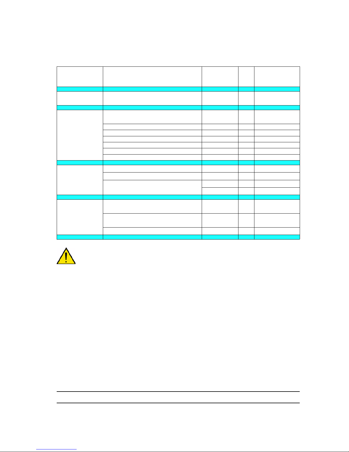
Carry out when the maintenance indicator light of the GNM 6080 is ON.
WARNING : (*): As soon as one of both terms is reached.
Sub-assembly Description
Part
number
Qty
Minimum
replacement
frequency
Nozzle support
(JR/JP)
O-ring J3STKL094 1 3 months
Barrel
Seal cartridge 910014338 1
6 months or 500.000
operations (*)
O-ring (Seal cartridge ) J3STKL005 1 3 months
O-ring chemically inert J3STKL032 1 6 months
O-ring FEP viton J2FENV435 1 12 months
O-ring chemically inert J3STKL078 1 12 months
O-ring chemically inert J3STKL002 1 12 months
O-ring chemically inert J3STKL019 1 12 months
Handle
O-ring (electrical connector) 160000041 1 12 months
O-ring (handle base)) 160000067 1 12 months
O-ring (air nipple)
J2FTCF018 1 12 m o nt hs
J3STKL018 1 12 months
Air valve
O-ring - chemically inert (outer of
valve)
J3STKL005 1 12 months
O-ring - chemically inert (inner of
valve)
J3STKL032 1 12 months
Sealing ring 900010256 1 12 months
Page 30
Index revision : C - March 2016 30 7105
WARNING : Before any maintenance work on the spray gun, alwa ys refer to the health and safe ty
instructions (see § 2 page 8
).
- Disconnect the control module from the power supply.
- Check that the air and paint circuits are not pressurised.
- Dump the paint circuit.
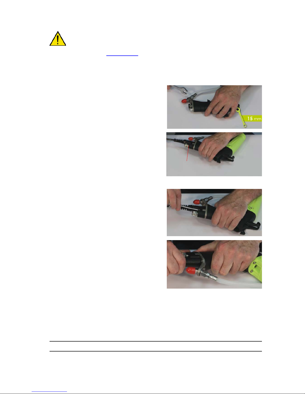
10.2. Electropneumatic coupling
• Step 1: Remove paint hose. Loosen the paint
hose nut with a 15mm open-ended spanner.
• Step 2: Unscrew the fitting nut of the 7/10
polyurethane air hose with an open-ended
spanner of 16.
• Step 3: Remove the low voltage cable with a 3mm
allen key, unscrew the two captive screws from
the electropneumatic coupling.
• Step 4: Pull the electropneumatic coupling apart
to disconnect.
• Step 5: Loosen the air nipple using a 14mm open-ended spanner and replace it.
Step 1
Step 2
Step 3
Step 4
Fitting
Page 31

Index revision : C - March 2016 31 7105
10.3. Paint Hoses
10.3.1. Paint hose - QD version (HR)
• Step 1: Side handle, unscrew the fitting using a
15mm open-ended spanner.
• Step 2: Release the paint hose from base.
• Step 3: Using a 21 mm open-ended spanner,
unscrew the upper nut of the paint hose, then
stop loosening manually by maintaining the nut
of bottom.
• Step 4: Check that the seal of the paint nut is in
place. Check that the two olives (P/N
910018200) are installed on the paint hose (the y
can be lost in the event of leakage caused by
inadequate tightening). In case olives must be
removed, replace them necessarily by news.
To reassemble, follow the steps in reverse order.
Tighten manually the upper paint hose nut until it levels the reinforcement of the barrel.
Step 1
Step 2
Step 3
Page 32
Index revision : C - March 2016 32 7105
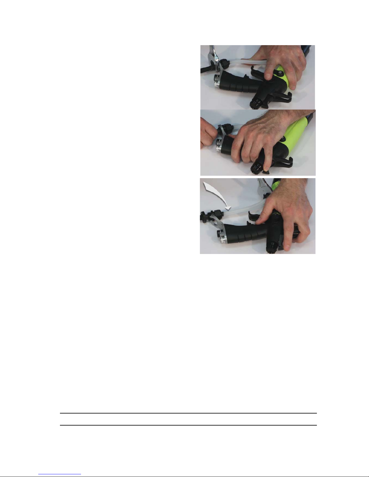
10.3.2. Paint hose LR
• Step 1: Unscrew the stuffing box locknut using a
27mm open-ended spanner, release the stuffing
box from the bracket.
• Step 2: Using a 21mm open-ended spanner,
loosen the upper paint hose nut. Unscrew the
nut, whilst rotating the hose
To reassemble, tighten the lower paint hose nut until it stops. Position the stuffing box locknut above
the bracket and the stuffing box below in the hexagonal socket. Tighten the stuffing box locknut onto the
bracket.
Step 1
Step 2
Page 33

Index revision : C - March 2016 33 7105
10.4. Spray head assembly
Round Spray and Fan spray nozzles
• Step 1: Unscrew the air cap ring by hand, then
remove the air cap.
• Step 2: Unscrew the nozzle assembly and the
nozzle support nut using the multipurpose
spanner.
• Step 3: Remove the nozzle support, pulling it in a
direction parallel to the barrel axis.
Replace the seal every three months (see § 13.7
page 56).
To reassemble, follow the steps in reverse order.
Step 1
Step 2
Step 3
Page 34
Index revision : C - March 2016 34 7105
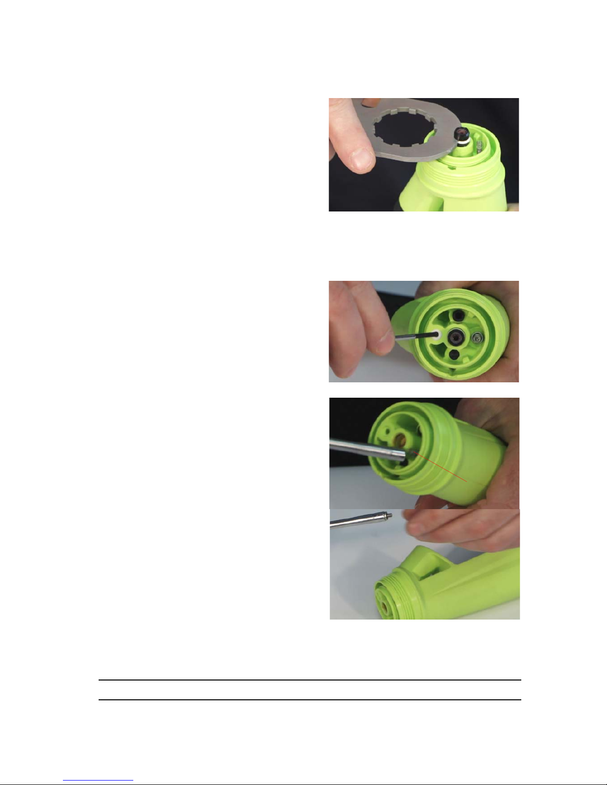
10.5. Barrel
• Step 1: Seal cartridge: Extract the cartridge from
the barrel using the multipurpose spanner. The
cartridge should be replaced every time it is
disassembled.
If the o-ring at the front of the cartridge is to be
replaced, removed it with a screwdriver, insert
the new o-ring, ensuring it is positioned correctly.
When reassembling, ensure the cartridge is
inserted in the correct orientation (white seal
facing outwards). Push the cartridge until it clips
into the barrel. Coat the white seal and the antiextrusion ring with a fine layer of vaseline.
• Step 2: Seal: Replace the seal every three
months. Remove the seal using a 2.5mm
screwdriver, taking care to avoid damaging the
barrel.
• Step 3: HV contact: Unscrew the HV contact
using a 4mm socket wrench. The fibre washer
should always be replaced whenever the device
is disassembled. Replace the HV contact if necessary, then screw back into the barrel.
Step 1
Step 2
HV Contact
Step 3
Page 35

Index revision : C - March 2016 35 7105
10.6. Paint needle
• Step 1: Unscrew the notched button at the rear of
the spray gun, retrieve the spring.
• Step 2: Press the trigger and pull manually the
paint needle towards the back.
WARNING : Every 4 or 5 reassemblies, add some
red dielectric grease (Ref.: H1GSYN037) in th e p as sag e ch a n ne l in the barre l .
10.7. Switch
• Step 1: With a 5,5 mm screwdriver, unscrew the
shouldered screw. Pull upwards the lever of the
switch.
• Step 2: Replace the o-ring (see § 13.3 page 52
).
Insert the new switch into its housing. Coat with
low threadlocker the fastening screw and tighten
the screw so that the switch is slightly resistant.
Step 1
Step 2
Step 1
Step 2
Page 36
Index revision : C - March 2016 36 7105
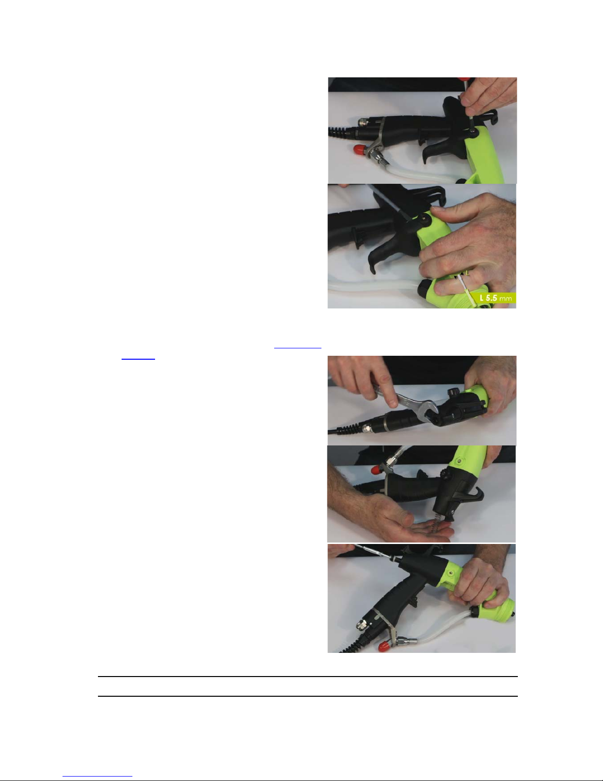
10.8. Trigger
• Step 1: Using a screwdriver, unscrew both
shouldered screws and release both sides of the
trigger.
Reassembling the trigger:
• Put in place one on the sides of the trigger on its
shoulder then slide the other side into its housing.
10.9. Air valve
• Step 1: Remove the paint needle (see § 10.6
page 35).
• Step 2: Unscrew the air valve stop nut using a 18
mm open-ended spanner.
Position the gun barrel to the top and recover the
spring and the air valve. If the parts do not fall, tap
in the palm of the hand.
or use the paint needle to extract the air valve.
Step 1
Step 2
Page 37
Index revision : C - March 2016 37 7105
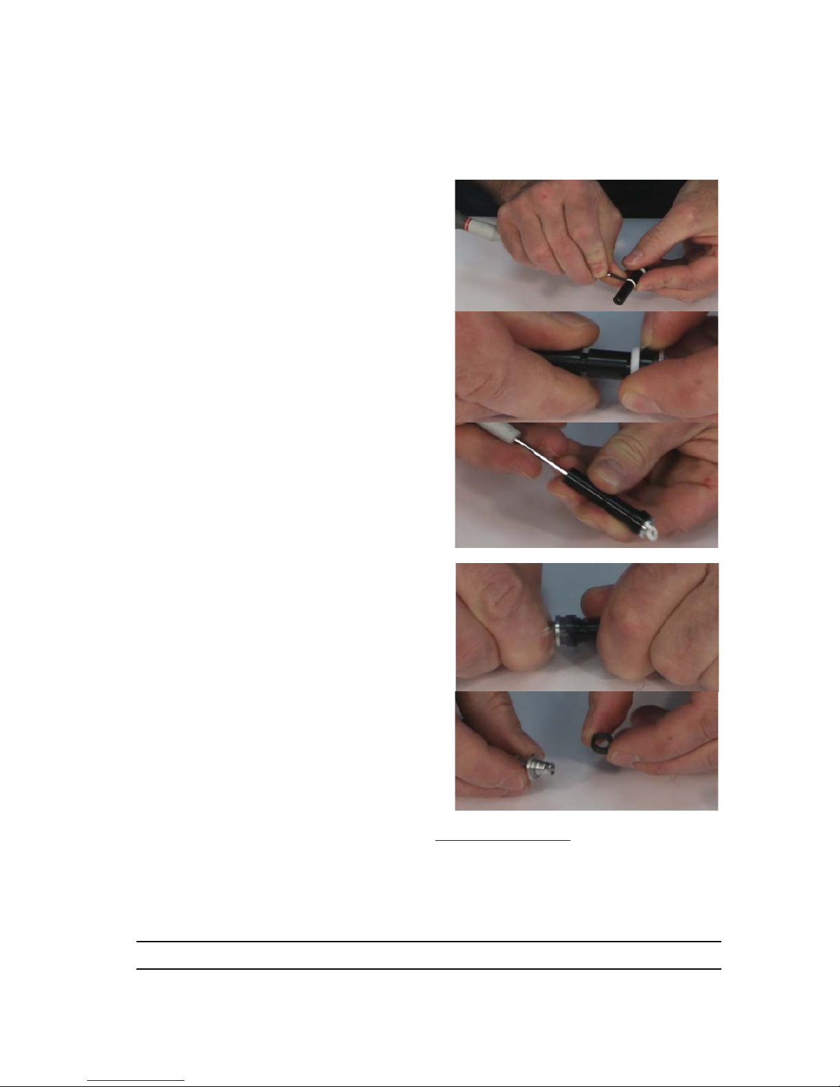
10.9.1. Repairing the air valve
Three levels of maintenance are possible:
• Level 1: Standard level of maintenance because the body of the air valve does not undergo any
friction nor wear.
• Level 2: Corrective maintenance, carry out if the valve body is damaged.
• Level 3: Exceptionnal maintenance, carry out if the magnet is lost or broken.
Level 1: Replacement of the three o-rings (P/N
J3STKL032 inner ring, J3STKL005 outer ring and
900010256 conical seal.
• For three seals, extract the old by taking care of
not damaging the body of the air valve (but they
can be destroyed).
• The conical seal must be pushed up to its clickand-ratchet work on the body of the air valve by
taking care not to damage its conical reach.
Level 2: If the valve body is damaged.
• Extract manually the aluminium ring or put a M4
screw in the ring, pull out in the axle of the part,
and remove the magnet by taking care to locate
its direction (silver plated side / black side).
• Put in place the magnet in the right direction (see § 10.9.1.1 page 38
) and retain the ring in the
body of the air valve by pushing firmly with the finger.
After complete reassembly of the spray gun, check the activation and the stop of the high
voltage. If the high voltage is permanently engaged or does not cut its elf: check the direction of
the magnet.
Page 38
Index revision : C - March 2016 38 7105
Level 3: If the magnet is broken or lost.
• Replacer the air valve (P/N 910015405) (see § 10.9 page 36
).
Before using the spray gun, check the activating and the stop of the high voltage.
If the high voltage is permanently activated, disassemble the handle and remove one of the washers
which adjust the position of the sensor reed, proceed step by step, don’t remove sever al washers at the
same time.
If the high voltage does not start, disassemble the handle and add a washer to adju st the position of the
sensor reed, proceed step by step, don’t add several washers at the same time.
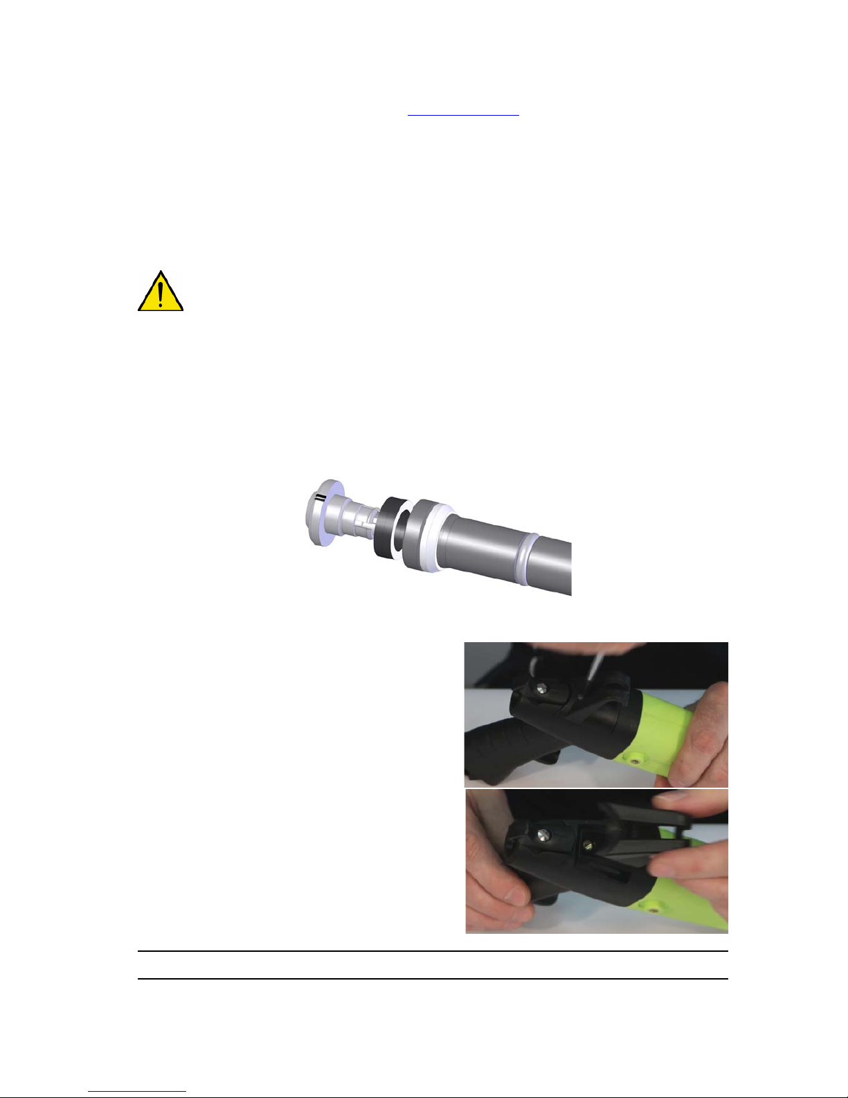
WARNING : Various thicknesses of washers can be in position, begin always to add or remove
the finest.
10.9.1.1. Direction of assembling of the magnet
• Case Nr 1: For the guns of the type 1 (see serial number). Rear support without groove, the side
silver plated of the magnet must be in contact with the shoulder of the rear support.
• Case Nr 2: For the guns of the type 2 (see serial number). Rear support with grooves, the black
side of the magnet must be in contact with the shoulder of the rear support.
10.10. Fixing hook
• Put the switch in position " I ". With a 5,5mm
screwdriver, unscrew the shouldered screw and
remove the hook by pulling upwards.
Page 39
Index revision : C - March 2016 39 7105
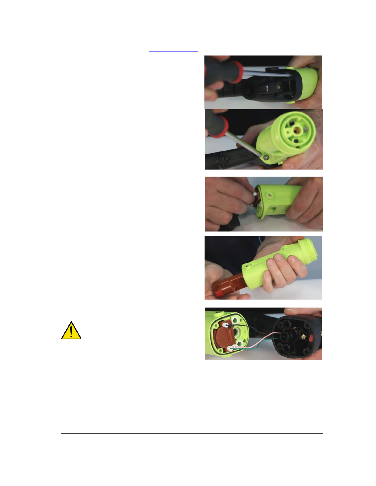
10.11. High voltage cascade
• Step 1: Remove the trigger (see § 10.8 page 36
), remove the paint needle.
• Step 2: Loosen the 4 screws fastening the barrel
on the handle with a 2mm Phillips screwdriver.
• Step 3: Unscrew, manually or with a small flat
pliers, the three connection wires of the high
voltage unit, pull carefully the contacts towards
the back.
• Step.4: Remove the high voltage contact in front
of the barrel (see § 10.5 page 34
). Withdraw the
high voltage unit.
WARNING : Attention with the c olors (terminal 1:
black, terminal 2: green, terminal 3: pink).
To reassemble, follow the steps in reverse order.
Replace the high-voltage cascade. Coat the cascade with red dielectric lubricant (P/N #
H1GSYN037) then insert it into its housing.
Push the cascade fully into the barrel. Connect the three wires and tighten the screws. Check the wear
of the o-rings, replace if necessary.
Step 3
Step 4
Step 2
1
2
3
Page 40

Index revision : C - March 2016 40 7105
10.12. Barrel
• Step 1: Remove the trigger see § 10.8 page 36
, and the paint needle.
• Step 2: Unscrew the four screws fastening the barrel on the handle.
• Step 3: Unscrew manually or with a small flat pliers the three connection wires of the h igh vo ltage
unit, pull carefully the contacts towards the back.
• Step 4: Replace the o-rings of the air ducts
and the air valve (Step 3: not obligatory):
Remove and replace the three o-rings.
• Step 5: Replace the o-ring barrel/handle
(Step 3: obligatory): Remove and replace the oring.
Replace this o-ring every year.
• Step 6: Replace the o-ring back of paint needle: Remove and replace the o-ring.
For reassembling follow the steps in reverse order.
Step 4
Step 5
Step 6
Page 41

Index revision : C - March 2016 41 7105
10.13. Handle
• Step 1: Separate the barrel from the handle.
• Step 2: Handle base
Unscrew the air nipple using a 6mm allen key.
Replace the seals every 12 months.
• Step 3: Undo both K35 x 14 screws with a 2mm
Phillip's screwdriver. Change the fibre washers
each time the screws are removed.
• Step 4: Lift the base to access the handle base
seal. This seal should be replaced every 12
months.
• Step 5: Push the electrical connector to release
it and remove from the base.
Replace the seal of the connector every 12
months.
• Step 6: Replacement of the base: unscrew
the screw of the ground wire using a 0 Phillip's
screwdriver, withdraw it and replace it.
To reassemble, follow the steps in reverse order. Insert the connector pin back into the base
foolproofing slot.
Coat the air nipple seals with dielectric lubricant.
Tighten the air nipple to 1.5 N.m torque.
Tighten the two K35 x 14 screws to 1.3 N.m torque.
Step 2
Step 3
Step 4
Step 6
Page 42

Index revision : C - March 2016 42 7105
10.14. Electric diagrams
10.14.1. Connection cable GNM 6080 / NANOGUN-MV
10.14.2. GNM 6080 trigger cable
(*)
Switch ”open”: NANOGUN-MV trigger releases.
Switch ” closed” : NANOGUN-MV trigger activated.
Characteristics of the switch: 0.5 A maxi / 24 VAC/DC maxi.
A Pink Primary transformer HVU 3
B Shield
C White REED sensor (trigger)
D Yellow Dallas chip
E Brown 0V commun puce / reed
F Third shield
G Green Primary transformer HVU 3
H Black Return IHV 1
E
D
C
G
F
B
A
A
H
G
F
E
D
C
B
Plug side GNM 6080
Plug side NANOGUN-MV
Pink
Brown
White
Yellow
Black
Green
Pink
Yellow
Brown
White
Green
Black
E
D
C
B
A
F
H
G
DES05943
Plug side GNM 6080
Page 43
Index revision : C - March 2016 43 7105
11. Cleaning
Always refer to the health and safety instruc tions befor e carrying out any work on the spray gun
(see § 2 page 8
).
11.1. Cleaning the product circuit
• Disconnect the GNM 6080 control module.
• Install a bucket of solvent in place of the paint container.
• Open the recirculation valve to clean the pump.
• Close the recirculation valve and hold down the trigger until clean solvent comes out of the spray
gun nozzle/tip.
11.2. Cleaning the spray gun
The spray gun must be cleaned immediately after use and at the end of the day, as with all paint guns.
The cleaning procedure described below should be followed carefully:
WARNING : It is formally forbidden to plunge the NANOGUN-MV into solvent.
WARNING : Use an appropriate solvent: non-greasy, non-chlorinated and with a hig h resistivity.
• Step 1: Disconnect the GNM 6080 control module.
• Step 2: Depressurise the spray gun air circuit.
• Step 3: Dump the spray gun paint circuit and rinse with an appro priate solvent (see § 2.4 page 10
).
• Step 4: Depressurise the spray gun paint circuit.
• Step 5: Dry the spray gun air cap with a soft, dry, lint-free cloth.
• Step 6: Unscrew the spray gun air cap ring and remove the air cap (see § 10.4 page 33
).
• Step 7: Clean the air cap with a solvent-dampened brush and then wipe dry.
• Step 8: Reassemble the air cap and ring.
• Step 9: Dry the compressed air spray gun (facing downwards) before restarting the GNM 6080
control module.
WARNING : Never disassemble the needle assembly when the paint hose contains paint or
solvent.
WARNING : Never soak or immerse the spray gun in solvent.
When cleaning the nozzle/tip, always point the spray nozzle/t ip towards t he g round
to prevent solvent or paint from flowing into the barrel ducts.
WARNING : After cleaning, the ducts and supply hose must be dried with compressed air to
remove all traces of solvent.
11.3. Waste disposal
Waste generated by use of the apparatus (spent solvent, unu sed paint, residue, dirty cloths, paint booth
slurry, water-wash spray booth run-off, used dry filters, ventilation air etc.) must be removed, transported
and disposed of in strict compliance with the applicable local regulations.
Page 44
Index revision : C - March 2016 44 7105
11.4. Demolition and Recycling
11.4.1. NANOGUN-MV
WARNING : All the parts can be contaminated by paint residues and/or of solvent.
Before proceeding to the demolition of the equipment,clean the spr ay gun and more
particularly the inside of paint hoses with an appropriate cleaning product and airdrying them with compressed air.
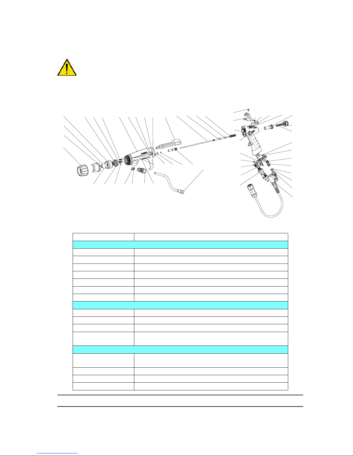
Item Material
Spraying area
1,6, 22,28,33,37 Plastics charged glass fiber or kevlar
31 Plastic charged PTFE or chemically inert rubber
28 Plastics charged with fibers, titanium
2 Plastics and stainless steel
5, 22 Chemically inert rubber
3* Brass
26 Polyethylene and stainless steel
Barrel area
14, 29* Plastic charged glass fiber
8, 19 Stainless steel
35, 39,40, 41, 42 Chemically inert rubber or fiber O-rings
25
Plastic, copper, steel, ceramic, electronic and electric
components ROHs
Air and product valve area
23, 24*
Tungsten, PEEK, stainless steel, chemically inert rubber,
PTFE, magnet (iron), aluminium
12*, 18*, 45* Stainless steel
16*, 17*, 21 Aluminium
32 Plastics, chemically inert rubber
28
37
35
24 45 17
12
34
18
44
42
20
30
4
43
23
26
282
1
2
10
25
29
22
42
41
39
40
41
8
42
15
27
19
16
9
3 14
19
8
19
6 5
33
21
13
11
36
36
38
32
31
7
Page 45
Index revision : C - March 2016 45 7105
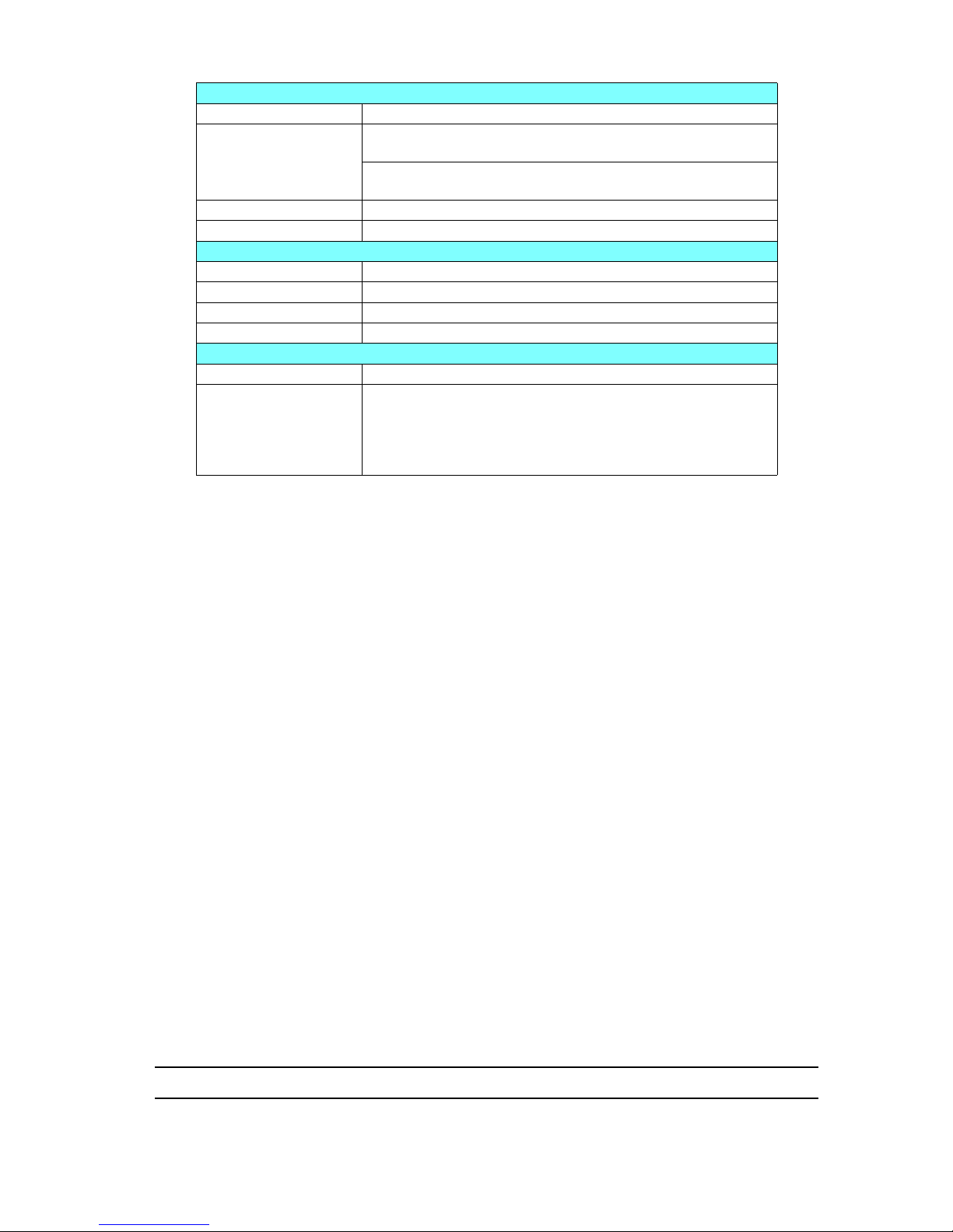
* These components (3, 12, 16, 17, 18, 24, 29, 45) can be soiled with dielectric grease.
Handle area
15, 34 Plastics charged glass fiber, stainless steel, brass, copper
Not shown
Sensor position trigger: electric components ROHs, plastic,
copper
connector at the bottom of the handle: ROHs electronic
components, plastic, copper
19 Stainless steel
27 Plastic charged glass fiber, magnet (iron)
Area base plate of handle connection towards the control module
13 Aluminium
11, 20, 42, 43, 44 Stainless steel
7, 36 Rubber
30 Plastics charged glass fiber, stainless steel, copper
Product /air hose area
Not shown Air hose: PU
Not shown
Product hose: polyethylene or elastomerized polyethylene
Connections: zinc coated steel and stainless steel
Sheath: polyamide
Stuffing box: plastic charged
Fitting: zinc coated steel and stainless steel
Page 46
Index revision : C - March 2016 46 7105
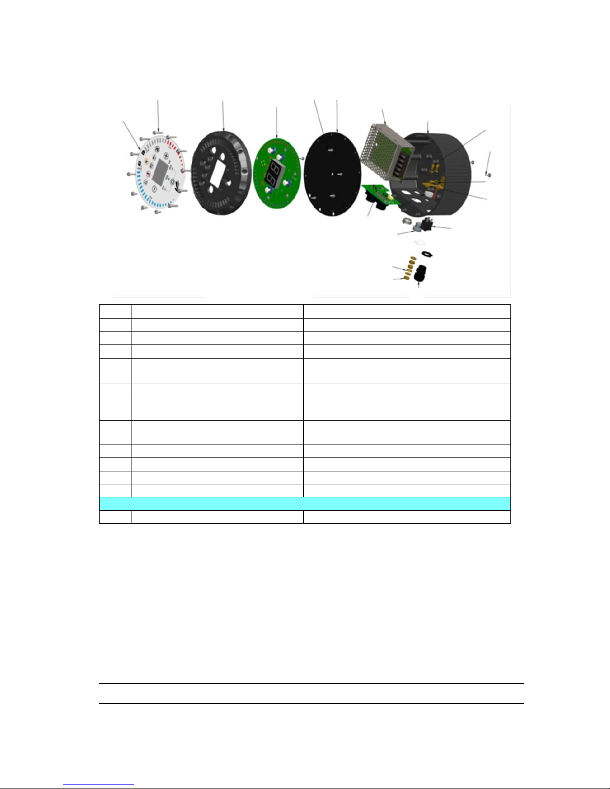
11.4.2. GNM 6080
* Attention, this component can be soiled with dielectric grease.
Item
Description
Material
1 Keyboard / front face* Plastic
2 Fastening screw of front face Stainless steel
3
Support of main board and front face
Aluminium
4 Main board
Electric and electronic components, printed
circuit ROHs
5 Rear metal sheet and fastening screw Steel
6 Connector board
Electric and electronic components, printed
circuit ROHs
7 Electric power
Electric and electronic components, printed
circuit ROHs
8 Box Aluminium
9 Fixation accessories Steel and brass
10 Electric switch Electric component ROHs
11 Stuffing box Plastic
Not shown
12 Power cable (not shown) Plastic and copper
2
1
3
4
5
5
7
8
9
9
9
9
10
11
9
9
9
6
Page 47
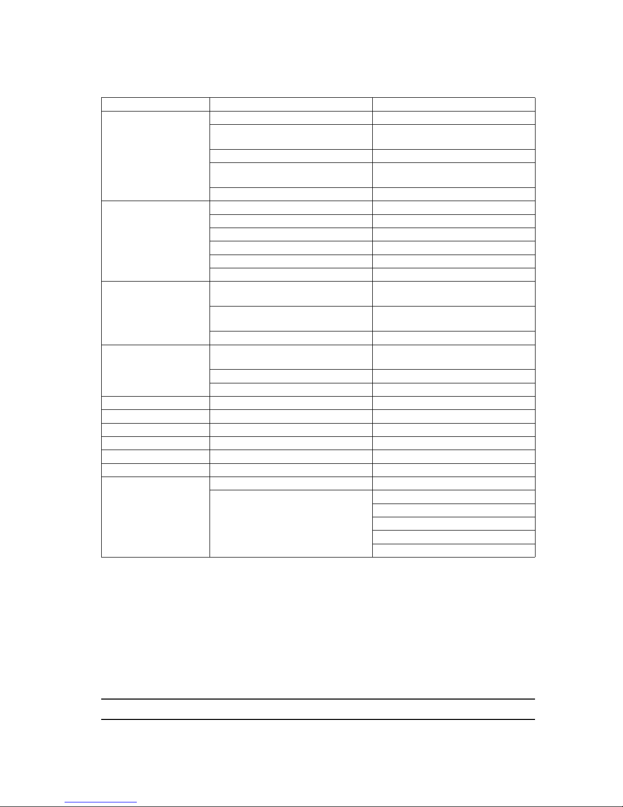
Index revision : C - March 2016 47 7105
12. Troubleshooting Guide
Faults Possible causes Remedies
Irregular paint spray
Air in paint circuit Dump the paint circuit
Paint flow too low
Increase pressure in pump or
pressure tank
Impurities in circuit Check filter, then drain circuit
Paint tank empty (or nearly)
Refill paint tank
Paint viscosity too high Check paint viscosity
Paint not fluid enough
when leaving spray
gun
Blocked nozzle/tip Clean nozzle/tip
Needle does not retract Check needle assembly
Clogged filter Clean filter
Insufficient pump pressure Check pump
Paint viscosity too high Check paint viscosity
Dia 6.35 mm paint hose clogged Unblock or replace paint hose
Paint flows out
continuously
Needle is obstructed and cannot
close
Remove nozzle/tip holder and clean
holder and seat. Clean needle tip
Worn needle
Replace needle and, if necessary,
the nozzle/tip holder
Nozzle/tip holder damaged Replace nozzle/tip holder
Paint comes out of air
cap air holes
Nozzle/tip insufficiently tightened
against seat
Tighten nozzle/tip
Damaged cartridge Replace cartridge
Damaged paint seal Replace seal
Poor spraying quality Nozzle/tip partially blocked Clean nozzle/tip
Paint flow too weak Increase paint flow
Viscosity too high Dilute paint
Insufficient air for spraying Increase air pressure
Paint flow too high Reduce paint flow
Paint injector damaged Replace the injector
Orange peel effect
Solvents evaporating too quickly Use heavier solvents
Paint droplets too large
Increase spraying distance
Dilute paint
Increase spraying air pressure
Decrease nozzle/tip size
Increase the electrostatic effect
Page 48
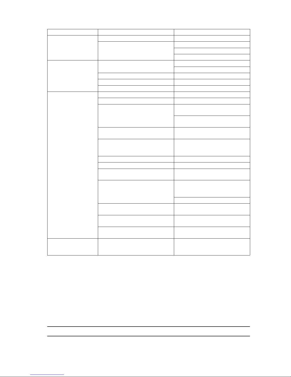
Index revision : C - March 2016 48 7105
Faults Possible causes Remedies
Paint running
Solvents evaporating too slowly Use lighter solvents
Spraying applied too slowly
Reduce paint flow
Increase spraying air pressure
Reduce the electrostatic effect
Paint spray
overloaded in middle
Paint flow too high
Reduce paint flow
Increase air pressure
Nozzle/tip too large Use a smaller nozzle/tip
Paint viscosity too great Dilute paint
Air holes partially blocked Clean spray head
Insufficient
electrostatic effect
High voltage power not on See display on control module
High voltage power insufficient Increase high voltage power
Distance between spray head and
part too great
Check NANOGUN-MV output
voltage
Spray from between 200 and 300
mm away
Part not grounded
Clean hooks. Check grounding
connection of parts conveyor
Excessive ventilation
Reduce paint booth air extraction
rate, ensuring the applicable
regulations are still complied with
Spraying air pressure too high Reduce spraying air pressure
Paint flow too high Reduce paint flow
Product resistivity too high
Reduce product resistivity to obtain
ρ < 500MΩ.cm
Control module short circuit:
- external
Clean outside of the spray gun with
a non-conductive solvent (ρ > 15
MΩ.cm)
Use a new, clean and dry case
Control module short circuit:
- via needle assembly
Replace seal cartridge and needle
Control module short circuit:
- via air channels
Clean the air channels of the barrel
Control module short circuit:
- via product hose
Increase the resistivity of paint so
that ρ > 5 MΩ.cm
Operator gets electric
shocks when touching
the part
Part not grounded or poorly
grounded
Page 49
Index revision : C - March 2016 49 7105
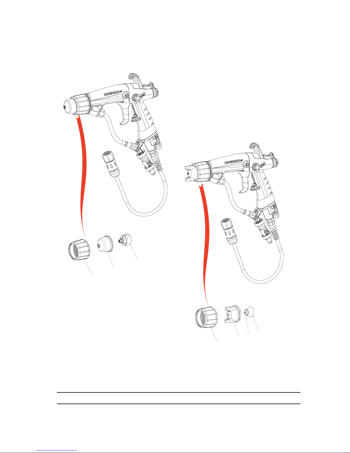
13. Spare Parts
13.1. NANOGUN-MV spray guns low pressure for high resistivity (HR) solvent paint ρ > 10MΩ.cm
DES05940
1
4
5
6
1
3
2
Round Spray Versions
JR 06 / JR 08 / JR 12
Fan Spray Version
Page 50
Index revision : C - March 2016 50 7105
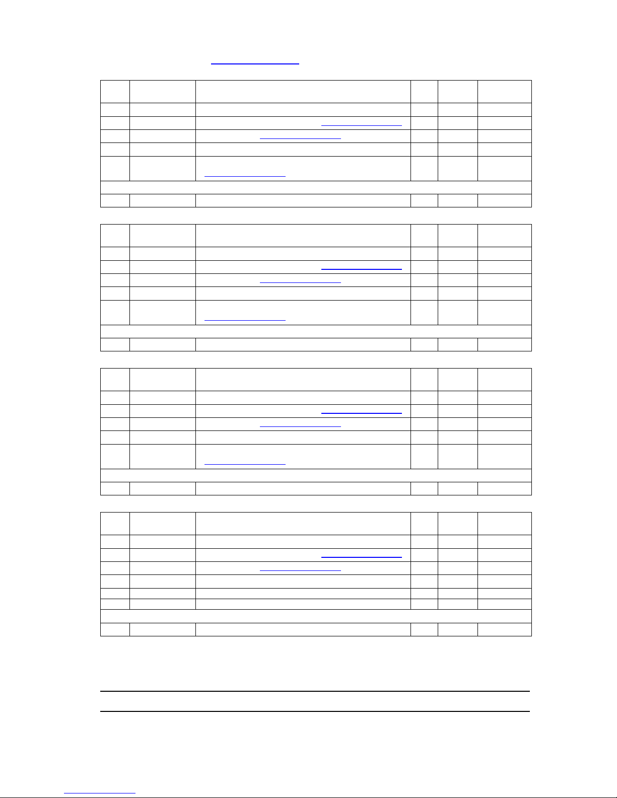
For the various options: see § 13.13 page 61.
(*)
Level 1: Standard preventive maintenance.
Level 2: Corrective maintenance.
Level 3: Exceptional maintenance.
Item Part number Description Qty
Unit of
sale
Spare Part
Level (*)
910018773 NANOGUN-MV JR 06 LP HR round spray 1 1 -
- NANOGUN-MV spray gun (see § 13.3 page 52
)- - -
1 910015921 Air cap ring (see § 13.6 page 56
) 11 3
2 900011365 Super vortex cap 1 1 3
3 910018322
JR06 Round spray nozzle
(see § 13.8 page 57
)
11 1
Not shown
050123306 M1/2 JIC adapter - F3/8NPS paint hose 1 1 3
Item Part number Description Qty
Unit of
sale
Spare Part
Level (*)
910016712 NANOGUN-MV JR 08 LP HR round spray 1 1 -
- NANOGUN-MV spray gun (see § 13.3 page 52
)- - -
1 910015921 Air cap ring (see § 13.6 page 56
)113
2 900010503 Super vortex cap 1 1 3
3 910003847
JR08 Round spray nozzle
(see § 13.8 page 57
)
11 1
Not shown
050123306 M1/2 JIC adapter - F3/8NPS paint hose 1 1 3
Item Part number Description Qty
Unit of
sale
Spare Part
Level (*)
910016711 NANOGUN-MV JR 12 LP HR round spray 1 1 -
- NANOGUN-MV spray gun (see § 13.3 page 52
)- - -
1 910015921 Air cap ring (see § 13.6 page 56
)113
2 900010504 Super vortex cap 1 1 3
3 910003920
JR12 Round spray nozzle
(see § 13.8 page 57
)
11 1
Not shown
050123306 M1/2 JIC adapter - F3/8NPS paint hose 1 1 3
Item Part number Description Qty
Unit of
sale
Spare Part
Level (*)
910016710 NANOGUN-MV JP LP HR Fan spray 1 1 -
- NANOGUN-MV spray gun (see § 13.3 page 52
)- - -
1 910015921 Air cap ring (see § 13.6 page 56
)113
4 900009014 High efficiency air cap 1 1 1
5 446028 Electrode 1 5 1
6 1406402 SP nozzle assembly 1 1 1
Not shown
050123306 M1/2 JIC adapter - F3/8NPS paint hose 1 1 3
Page 51
Index revision : C - March 2016 51 7105
13.2. NANOGUN-MV, low Pressure spray guns for solvent paint 0.5 MΩ.cm < ρ < 500 MΩ.cm
WARNING : NANOGUN-MV Low Pressure low resistivity spray guns include the same
components, except the product hoses.
Part number Description Qty
Unit of
sale
Spare Part
Level
910018774-075 NANOGUN-MV JR 06 LP LR, hose length: 7.5 m 1 1 -
Part number Description Qty
Unit of
sale
Spare Part
Level
910018774-150 NANOGUN-MV JR 06 LP LR, hose length: 15 m 1 1 -
Part number Description Qty
Unit of
sale
Spare Part
Level
910017190-075 NANOGUN-MV JR 08 LP LR, hose length: 7.5 m 1 1 -
Part number Description Qty
Unit of
sale
Spare Part
Level
910017190-150 NANOGUN-MV JR 08 LP LR, hose length: 15 m 1 1 -
Part number Description Qty
Unit of
sale
Spare Part
Level
910017189-075 NANOGUN-MV JR 12 LP LR, hose length: 7.5 m 1 1 -
Part number Description Qty
Unit of
sale
Spare Part
Level
910017189-150 NANOGUN-MV JR 12 LP LR, hose length: 15 m 1 1 -
Part number Description Qty
Unit of
sale
Spare Part
Level
910017188-075 NANOGUN-MV JP LP LR, hose length: 7.5 m 1 1 -
Part number Description Qty
Unit of
sale
Spare Part
Level
910017188-150 NANOGUN-MV JP LP LR, hose length: 15 m 1 1 -
Page 52

Index revision : C - March 2016 52 7105
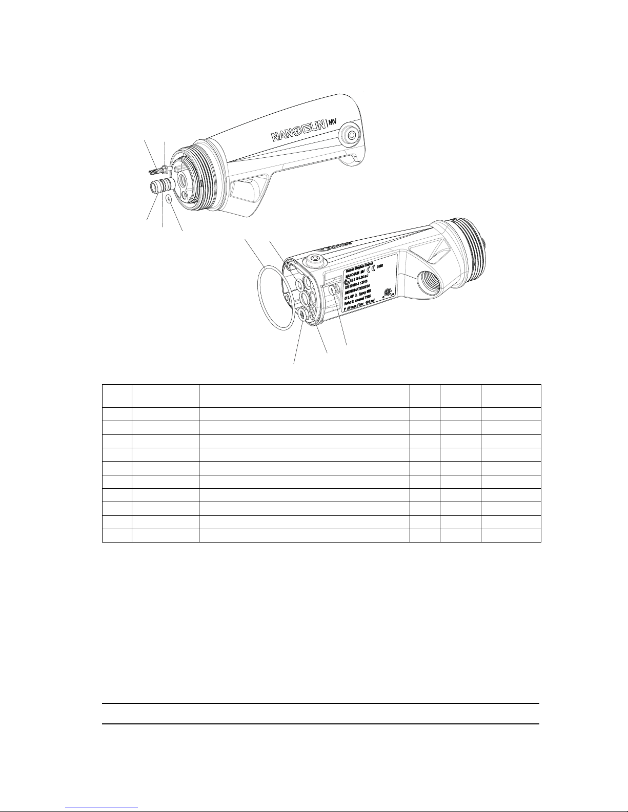
13.3. NANOGUN-MV spray guns, all versions
DES05946
1
2
3
4
5
6
7
8
10
12
13
18
19
20
21
14
15
22
23
15
24
25
26
27
28
29
30
8
31
32
33
11
16
17
9
Page 53

Index revision : C - March 2016 53 7105
(*)
Level 1: Standard preventive maintenance.
Level 2: Corrective maintenance.
Level 3: Exceptional maintenance.
Item Part number Description Qty
Unit of
sale
Spare Part
Level (*)
- NANOGUN-MV spray gun - - -
1 900000320 Nozzle nut 1 1 3
2 910015721 Nozzle support (see § 13.7 page 56
) 11 1
3 910018202 Equipped barrel (see § 13.4 page 54
) 11 3
4 900010237 Trigger 1 1 3
5 910015508 High voltage unit 1 1 3
6 910015944 NANOGUN-MV equipped handle 1 1 3
7 900010239 Fixing hook 1 1 3
8 900010385 Shouldered C M4 screw 4 1 3
9 900013808 PTFE flat washer (included in item10) 1 1 2
10 910018204
ON/OFF button with magnet and o-ring
(included in item 6)
11 3
11 J3STKL005 Chemically inert o-ring (included in item 10) 1 1 1
12 900010240 Paint flow button 1 1 3
13 900010265 8 bar paint spring 1 1 1
14 250000036 Screw securing handle/barrel 4 1 3
15 J4BRND039 Fiber seal for securing screw 6 1 3
16 160000041 O-ring chemically inert (included in item 6) 1 1 1
17 160000067 O-ring FKM red (included in item 6) 1 1 1
18
910018207 HR spray gun base, marked 7 bar 1 1 3
910018210 LR spray gun base, marked 7 bar 1 1 3
19 910006118 Air nipple 1 1 2
20 J2FTCF018 O-ring FKM black (included in item19) 2 1 1
21 J3STKL018
O-ring chemically inert grey
(included in item19)
11 1
22 910015869
Electropneumatic coupling sets
(see § 13.10 page 58
)
11 3
23 250000037 Securing screw of handle base 2 1 3
24 900010605 55° elbow 1 1 3
25 250000214 Elbow securing screw 1 1 3
26 910014166 Lateral tape equipped (included in item 6) 11 3
27 J2FTDF121 O-ring FKM black (included in item 26) 1 1 1
28 910018203 Air valve (see § 13.5 page 55
) 11 3
29 900010253 Needle rear stop 1 1 3
30 910018219 Needle (see § 13.9 page 58
) 11 1
31 J2FTDF121 O-ring FKM black (included in item 32) 1 1 1
32 910015931 Paint nut equipped 1 1 2
33 J2FTCF178 O-ring FKM black (included in item 32) 1 1 1
Page 54
Index revision : C - March 2016 54 7105
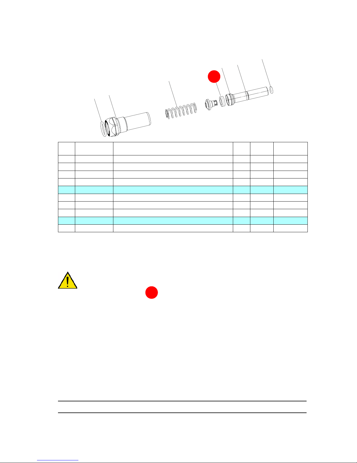
13.4. Barrel assembly
(*)
Level 1: Standard preventive maintenance.
Level 2: Corrective maintenance.
Level 3: Exceptional maintenance.
Item Part number Description Qty
Unit of
sale
Spare Part
Level (*)
910018202 Barrel assembly 1 1 3
1 1407354 HV contact 1 1 1
2 J2CRAN031 Sealing ring of contact 1 1 1
3 J3STKL002 O-ring, chemically inert 1 1 1
4 910014338 Seal cartridge 1 1 1
5 J3STKL005 O-ring, chemically inert (included in item 4) 1 1 1
6 J2FENV435 O-ring FEP viton 1 1 1
7 J3STKL078 O-ring, chemically inert 2 1 1
8 J3STKL032 O-ring, chemically inert 1 1 1
9 J3STKL019 O-ring, chemically inert 1 1 1
DES05941
1
3
4
5
6
7
8
9
7
2
Page 55
Index revision : C - March 2016 55 7105
13.5. Air valve and Nut air valve
(*)
Level 1: Standard preventive maintenance.
Level 2: Corrective maintenance.
Level 3: Exceptional maintenance.
WARNING : Get back the magnet on the old air valve to keep the same values of triggering.
In case of loss of the magnet, contact Sames Technologies.
Item Part number Description Qty
Unit of
sale
Spare Part
Level (*)
910018203 Air valve 1 1 3
1 900010256 Sealing ring 1 1 1
2 J3STKL005 O-ring, chemically inert (outer of valve) 1 1 1
3 J3STKL032 O-ring, chemically inert (inner of valve) 1 1 1
910015922 Nut air valve equipped 1 1 3
4 J2FTDF155 O-ring, FKM black 1 1 1
5 J2FTDF160 O-ring, FKM black 1 1 1
6 900009024 Air spring 1 1 1
DES05944
6
1
2
3
5
4
A
A
Page 56

Index revision : C - March 2016 56 7105
13.6. Air cap ring
(*)
Level 1: Standard preventive maintenance.
Level 2: Corrective maintenance.
Level 3: Exceptional maintenance.
13.7. Nozzle support
(*)
Level 1: Standard preventive maintenance.
Level 2: Corrective maintenance.
Level 3: Exceptional maintenance.
Item Part number Description Qty
Unit of
sale
Spare Part
Level (*)
910015921 Air cap ring 1 1 3
1 900010497 Slide ring 1 1 3
2 J2FENV445 O-ring FEP/FKM 1 1 1
Item Part number Description Qty
Unit of
sale
Spare Part
Level (*)
910015721 Nozzle support - LP Models 1 1 1
1 J3STKL094 O-ring - chemically inert 1 1 1
DES05945
1
2
DES04110
1
Page 57
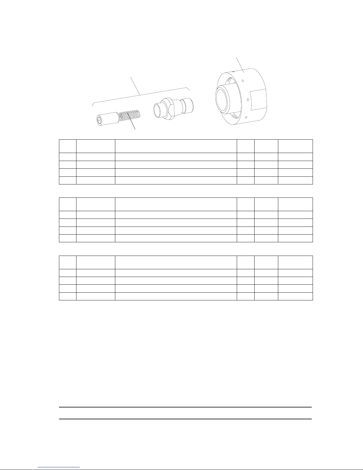
Index revision : C - March 2016 57 7105
13.8. Round Nozzle assemblies - LP Models
(*)
Level 1: Standard preventive maintenance.
Level 2: Corrective maintenance.
Level 3: Exceptional maintenance.
Item Part number Description Qty
Unit of
sale
Spare Part
Level (*)
910018322 JR06 Nozzle assembly 1 1 1
1 455234 Injector - Calibre 6 1 5 1
2 1305211 Vortex Nozzle 1 1 1
3 448110 Electrode (included in item1) 1 10 1
Item Part number Description Qty
Unit of
sale
Spare Part
Level (*)
910003847 JR08 Nozzle assembly 1 1 1
1 455235 Injector - Calibre 8 1 5 1
2 1305211 Vortex Nozzle 1 1 1
3 448110 Electrode (included in item1) 1 10 1
Item Part number Description Qty
Unit of
sale
Spare Part
Level (*)
910003920 JR12 Nozzle assembly 1 1 1
1 455236 Injector - Calibre 12 1 5 1
2 1305211 Vortex Nozzle 1 1 1
3 448110 Electrode (included in item1) 1 10 1
DE S04198
1
2
3
Page 58

Index revision : C - March 2016 58 7105
13.9. Needle assembly
(*)
Level 1: Standard preventive maintenance.
Level 2: Corrective maintenance.
Level 3: Exceptional maintenance.
13.10. Electropneumatic coupling sets
Item Part number Description Qty
Unit of
sale
Spare Part
Level (*)
910018219 Needle assembly 1 1 3
1 X4KEHU003 H M3 U nut 1 1 3
Item Part number Description Qty
Unit of
sale
Spare
Part
Level
910015869-100 HR-LR 10m Electropneumatic coupling 1 1 3
910015869-200 HR-LR 20m Electropneumatic coupling 1 1 3
1 F6RLUF171 Straight union - male 1 1 3
2
910021087-100
Polyurethane air hose - Ext. D: 10
10 m
m1
910021087-200 20 m
3 F6RLHG362 Female NPT / Male BSP adapter 1 1 3
DES05934
1
DES05933
1
2
3
GNM 6080 connection
Page 59

Index revision : C - March 2016 59 7105
13.11. Paint hoses
13.11.1. For NANOGUN-MV Low Pressure and High Resistivity spray guns
13.11.2. For NANOGUN-MV Low Pressure and Low Resistivity spray guns
(*)
Level 1: Standard preventive maintenance.
Level 2: Corrective maintenance.
Level 3: Exceptional maintenance.
Item Part number Description Qty
Unit of
sale
Spare Part
Level (*)
For NANOGUN-MV JR/JP spray guns
1
910017065-075 HR/LP product hose - 7.5m black Dia 61 1 1
910017065-150 HR/LP product hose - 15m black Dia 61 1 1
2 050123306 M1/2 JIC adapter - F3/8NPS 1 1 2
3 910018201 Paint hose equipped Dia:4 mm 1 1 2
4 910018200
Set of olives for outer 10 hoses
(included in item 3)
11 2
Item Part number Description Qty
Unit of
sale
Spare Part
Level (*)
For NANOGUN-MV JR/JP spray guns
1
910020516-075 LR /LP product hose - 7.5m PTFE Dia 61 1 1
910020516-150 LR /LP product hose - 15m PTFE Dia 61 1 1
2 910018200 Set of olives for outer 10 hoses 1 1 2
3 910018292 Stuffing box and nut 1 1 2
1
2
3
4
1
2
3
Page 60
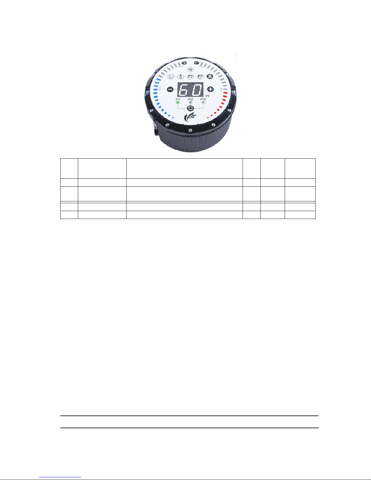
Index revision : C - March 2016 60 7105
13.12. GNM 6080 Control module
(*)
Level 1: Standard preventive maintenance.
Level 2: Corrective maintenance.
Level 3: Exceptional maintenance.
Item Part number Description Qty
Unit of
sale
Spare
Part
Level
910017193 CE GNM 6080 control module 1 1 3
910017192
CSA GNM 6080 control module
(USA-CANADA only)
11 3
910005759 GNM 6080 attachment kit 1 1 3
842635 5-m ground cable, lug dia.: 6 11 3
Page 61

Index revision : C - March 2016 61 7105
13.13. Options for NANOGUN-MV Low Pressure spray guns
13.13.1. Fan Spray Air Caps
(*)
Level 1: Standard preventive maintenance.
Level 2: Corrective maintenance.
Level 3: Exceptional maintenance.
13.13.2. In-line product filters
These small filters are fitted in the spray gun handle (with HR models).
WARNING : The filter is delivered with a 6mm screen as standard. Before installation of low
pressure models, you are advised to replace the screen nr 6 from the initial design
with a screen nr 12.
With LR models, it is necessary ro remove the fitting F 3/8 NPT- M1/2 JIC located at the pump outlet
and to replace it by the filter.
Part number Description Qty
Unit of
sale
Spare Part
Level (*)
737549 Air Cap (fan spray) Option 1 1
737550 SPE Air Cap (narrow fan spray) Option 1 1
737552 SPL Air Cap (broad fan spray) Option 1 1
Description Part number Versions
Filter (Male-Female 1/2 JIC) 155010100
LP HR
Screen nr 12 129609909
Page 62
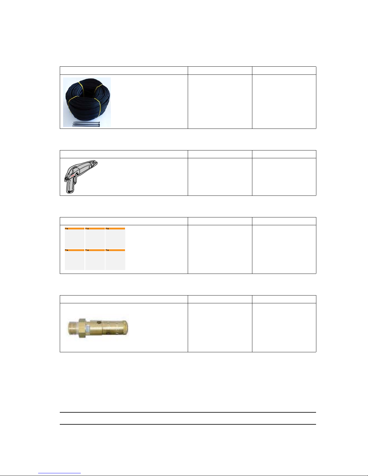
Index revision : C - March 2016 62 7105
13.14. Appendices
13.14.1. Protective hose covering
This covering can be used to protect hoses and cables to ensure long life and flexibility.
13.14.2. Protective case for spray gun
13.14.3. Warning notice
13.14.4. Safety valve
Description Part number Unit of sale
Rilsan Protective hose
covering with 30 collars
910021086 50 m roll
Description Part number Unit of sale
Protective case
900011711 10
Description Part number Unit of sale
Warning
notice
1407684 1
Description Part number Unit of sale
Safety valve 6.5 bar
1/4 G
903080401 1
DES01269
N˚ Sames 1407684
This sign must be hung in the booth.
Manual electrostatic equipment for the application of paint or varnish
• This equipment must only be used by SAMES trained personnel.
• The command module must be located at least 1,5m from the booth openings.
• The use of the command module must be completely dependent upon the running
of the booth's exhaust fan.
• Regroup the cables and pipes arriving to the spray gun to prevent them from
dragging on the ground where they could be severed.
• Only metallic recipients must be used for cleaning liquids. They must definitely be
grounded.
• Use cleaning liquids with a flash point higher than ambient temperature.
• Correctly ground all of the metallic parts in the booth, as well as the parts to be
painted.
• The operator and persons working nearby must wear antistatic shoes.
• The operator's hand must be in contact with the spray gun grip.
• Work on an antistatic floor such as bare concrete or a metallic grating.
• Switch off the command module for any maintenance operation, in particular for the
cleaning of the nozzle and the cap, and for the rinsing of the paint circuit with the
cleaning liquid.
• If the spray gun is equipped with a trigger lock, it must be engaged during the
cleaning of the nozzle and the cap and during a prolonged stop.
• The electrostatic application equipment must be maintained on a regular basis and
repaired according to the instructions in the manual.
WARNING
GB
WARNUNG
Elektrostatisches Handgerätzum Auftragen von Farben/Lacken von
• Dieses Gerät darf nur durch von SAMES ausgebildetem Personal bedient werden.
• Das Steuermodul ist mindestens 1,5 m von den Öffnungen der Kabine entfernt
anzubringen.
• Die Inbetriebnahme des Steuermoduls muss vom Betrieb des Ventilators des
Abzugs der Kabine abhängig sein.
• Zur Lackierpistole führende Kabel und Schläuche gruppieren, um zu vermeiden,
dass diese auf dem Boden liegen, wo sie beschädigt werden können.
• Für Reinigungsflüssigkeiten sind ausschliesslich Metallbehälter zu verwenden. Diese
müssen zuverlässig geerdet werden.
• Reinigungsflüssigkeiten mit einem Flammpunkt über der Raumtemperatur
verwenden.
• Alle Metallteile der Kabine sowie die zu beschichtenden Werkstücke sachgemäss
erden.
• Das Bedienungspersonal und Personal, das in unmittelbarer Nähe arbeitet haben
antistatisches Schuhwerk zu tragen.
• Die Hand des Bedieners muss direkten Kontakt zum Griff der Pistole haben.
• Auf antistatischem Fussboden, wie roher Beton, oder Metallrostfussboden arbeiten.
• Vor Wartungsarbeiten ist das Steuermodul auszuschalten, insbesondere für die
Reinigung der Düse, des Aufsatzes und zum Spülen des Lackkreislaufs mit
Reinigungsmittel.
• Wenn die Lackierpistole mit einer Sicherheitssperrvorrichtung für den Abzug
versehen ist, ist diese bei Reinigung de Düse, des Aufsatzes und einer längeren
Unterbrechung zu verriegeln.
• Die elektrostatische Beschichtungsanlage ist regelmässig zu warten und unter
Einhaltung der Anweisungen im Benutzerhandbuch zu reparieren.
Dieses Schild muss in der Kabine angebracht werden.
DE
WAARSCHUWING
Elektrostatische handapparatuur voor applicatie van verf/vernis
• Dit apparaat mag alleen door SAMES opgeleid personeel worden gebruikt.
• De bedieningsmodule moet zich op minder dan 1,5m afstand van de
cabineopeningen bevinden.
• De inwerkingstelling van de bedieningsmodule moet onderworpen zijn aan de
inschakeling van de zuigventilator van de cabine.
• Groepeer de kabels en leidingen die bij het pistool uitkomen zodat ze niet over de
grond slepen, waar ze kunnen worden afgesneden.
• Gebruik alleen metalen bakken voor de reinigingsvloeistoffen. Zij dienen op veilige
wijze op de grond te worden gezet.
• Gebruik reinigingsvloeistoffen met een vlampunt dat hoger is dan de
omgevingstemperatuur.
• Zorg voor een degelijke aardaansluiting van alle metalen cabine- onderdelen en alle
verfbare delen.
• De gebruiker en het personeel in zijn nabijheid dienen antistatisch schoeisel te
dragen.
• De hand van de gebruiker heeft direct contact met de kolf van het pistool.
• Werk op een antistatische grond zoals beton of een metalen rooster.
• Schakel de bedieningsmodule uit voor alle onderhoudshandelingen, vooral bij
reiniging van de loop of de beschermkap en bij spoeling van het verfcircuit met de
reinigingsvloeistof.
• Als het pistool is uitgerust met een trekkervergrendeling, dan dient u deze te
gebruiken tijdens reiniging van de loop of de beschermkap en tijdens langdurige
uitschakeling.
• De elektrostatische applicatieapparatuur dient regelmatig te worden onderhouden
en gerepareerd volgens de aanwijzingen in de gebruikshandleiding.
Bevestig deze plaat in de cabine.
NL
ADVARSEL
Manuelt udstyr til elektrostatisk påføring af maling/lak
• Udstyret må kun anvendes af personale, der er uddannet af SAMES.
• Betjeningsmodulet skal være anbragt mindst 1,5m fra kabinens åbninger.
• Betjeningsmodulet må kun kunne tændes, når kabinens udsugningsventilator er i
gang.
• Alle kabler og slanger, der er forbundet til pistolen, bør samles for at undgå, at de
flyder på gulvet, hvor de risikerer at blive skåret over.
• Rengøringsvæskerne må kun opbevares i metalbeholdere. Disse skal være sikkert
forbundet med jord.
• Der skal bruges rengøringsvæsker med et flammepunkt over stuetemperatur.
• Alle metalliske dele i kabinen såvel som emnet, der skal males, skal jordes korrekt.
• Operatøren og de personer, der arbejder i nærheden, skal bære antistatisk fodtøj.
• Operatørens hånd skal være i direkte berøring med pistolskæftet.
• Der skal arbejdes på et antistatisk underlag, såsom rå beton eller metalriste.
• Betjeningsmodulet skal sættes ud af drift inden al vedligeholdelse, specielt ved
rengøring af dysen eller hætten og rensning af malingskredsløbet vha.
rengøringsvæsken.
• Hvis pistolen er udstyret med en anordning til aflåsning af aftrækkeren, skal denne
være slået til under rengøringen af dysen eller hætten og ved længerevarende
standsninger.
• Udstyret til elektrostatisk påføring skal vedligeholdes regelmæssigt og repareres
ifølge forskrifterne i brugsvejledningen.
Dette skilt skal være anbragt i kabinen.
DK
VARNING
Manuell elektrostatisk utrustning för applikation av färg/lack
• Denna utrustning får endast användas av personal utbildad av SAMES.
• Manövermodulen skall vara belägen minst 1,5 m från hyttöppningana.
• Igångsättningen av modulen skall förutsätta inkoppling av hyttens utsugningsfläkt.
• Samla ihop kablar och slangar som går in på pistolen så att de inte ligger i vägen
på golvet, där de riskerar att skäras av.
• Endast metallbehållare får endast för rengöringsvätskor. De skall jordas på säkert
sätt.
• Använd rengöringsvätskor med en flampunkt som ligger över
omgivningstemperaturen.
• Jorda på korrekt sätt alla metalliska delar av hytten, liksom de delar som skall
målas.
• Operatören och personer som arbetar i närheten av de metalliska delarna skall
bära antistatiska skodon.
• Operatörens hand skall vara i direkt kontakt med pistolkolven.
• Arbeta på ett antistatiskt golv av typ bar betong eller en metallisk gallerdurk.
• Koppla bort manövermodulen vid varje underhållsarbete, i synnerhet vid rengöring
av munstycket, hatten och sköljningen av målningskretsen med rengöringsvätska.
• Om pistolen är utrustad med en avtryckarlåsning, skall denna vara ilagd vid
rengöringen av munstycket, hatten och vid ett långvarigt stopp.
• Den elektrostatiska applikationsutrustningen skall underhållas regelbundet och
repareras i enlighet med anvisningarna i användarmanualen.
Denna skylt skall placeras i hytten.
SE
VAROITUS
In Käsikäyttöiset sähköstaattiset maalaus-/lakkausruiskut
• Laitteita saa käyttää vain SAMESin kouluttama henkilöstö.
• Ohjausmoduuli on sijoitettava vähintään 1,5 m päähän maalauskopin aukoista.
• Ohjausmoduulin toiminta on kytkettävä maalauskopin imutuulettimen
käynnistymiseen.
• Katkeamisvaaran välttämiseksi maalausruiskun johdot ja letkut on sijoitettava siten,
että ne eivät laahaa maata.
• Puhdistusaineille käytettävä ainoastaan metallisäiliöitä. Säiliöiden maadoitus on
varmistettava.
• Käytettävä puhdistusaineita, joiden leimahduspiste on korkeampi kuin ympäristön
lämpötila.
• Kaikkien maalauskopin metalliosien sekä maalattavan kappaleen asianmukaisesta
maadoituksesta on huolehdittava.
• Laitteiston käyttäjän ja sen läheisyydessä työskentelevien on pidettävä antistaattisia
jalkineita.
• Käyttäjän käden on oltava suorassa kosketuksessa maalauspistoolin peräosan
kanssa.
• Työskentelytasona on oltava antistaattinen pinta, kuten paljas betoni tai metalliritilä.
• Ohjausmoduulista on katkaistava virta kaikkien huoltotoimien ajaksi, etenkin
puhdistettaessa suutinta tai suojakupua ja huuhdottaessa maalikiertoa
puhdistusnesteellä.
• Jos pistoolissa on liipaisimen lukitustoiminto, sitä on käytettävä puhdistettaessa
suutinta tai suojakupua ja laitteiston ollessa pitempään käyttämättä.
• Sähköstaattinen maalauslaitteisto on huollettava säännöllisesti ja korjaukset on
tehtävä käyttöohjeiden mukaisesti.
Tämä kilpi on sijoitettava maalauskoppiin.
FI
DES00790
Page 63
Index revision : C - March 2016 63 7105
14. The different versions
14.1. Equipments
DES05994
Titre Pistole t NANOGUN-MV "Basse pression" LP
Title NANOGUN-MV Gun type "low p ressure"LP
Pistolet NANOGUN-MV CE+CSA
PISTOLET "Basse pression" LP / "Haute résisvité " HR
N° GUN Low Pressure/High Resisvity GUN
CE + CSA
910016710 HAUTE RESI STIVITE JET PLAT
910018773 HAUTE RESI STIVITE JET ROND Ø6
910016712 HAUTE RESI STIVITE JET ROND Ø8
910016711 HAUTE RESI STIVITE JET ROND Ø12
910017188-075 BASS E RESISTI VITE JE T PLAT LG 7,5M
910017188-150 BASS E RESISTI VITE JE T PLAT LG 15M
910018774-075 BASS E RESISTI VITE JE T ROND Ø6 LG 7,5M
910018774-150 BASS E RESISTI VITE JE T ROND Ø6 LG 15M
910017190-075 BASS E RESISTI VITE JE T ROND Ø8 LG 7,5M
910017190-150 BASS E RESISTI VITE JE T ROND Ø8 LG 15M
910017189-075 BASS E RESISTI VITE JE T ROND Ø12 LG 7,5M
910017189-150 BASS E RESISTI VITE JE T ROND Ø12 LG 15M
EQUIPEMENT NANOGUN-MV CE EQUIPEMENT NANOGUN-MV CSAcus
N° GUN SET NANOGUN-MV CE N° GUN SET NANOGUN-MV CSAcus
910017223-07 E.NANOGUN- MV LP/HR JP LG7,5 EU 910017223- 072 E. NANOG UN- MV LP/HR J P LG7,5 US
910017223-15 E.NANO GUN- MV LP/HR JP LG15 EU 910017223-152 E. NANOG UN- MV LP/HR J P LG15 US
910017224-07 E.NANO GUN- MV LP/HR JRØ8 LG7, 5 EU 910017224- 072 E. NANOG UN- MV LP/HR JRØ8 LG 7,5 US
910017224-15 E.NANO GUN- MV LP/HR JRØ8 LG15 EU 910017224-152 E.N ANOG UN-M V LP/HR JRØ8 LG 15 US
910017741-07 E.NANO GUN- MV LP/HR JRØ12 LG7. 5 910017741-072 E. NANOG UN- MV LP/HR J RØ12 LG7.5U S
910017741-15 E.NANO GUN- MV LP/ HR JRØ12 LG15 EU 910017741-152 E.NANO GUN- MV LP/ HR JRØ12 LG15 U S
910017221-07 E.NANO GUN- MV LP/LR JP LG7, 5 EU 910017221-072 E. NANOG UN- MV LP/LR JP LG7, 5 US
910017221-15 E.NANO GUN- MV LP/LR JP LG15 EU 910017221-152 E.NANO GUN- MV LP/LR JP LG15 U S
910017222-07 E.NANO GUN- MV LP/LR JRØ8 LG7, 5 EU 910017222-072 E. NANOG UN- MV LP/LR JRØ8 LG 7,5 US
910017222-15 E.NANO GUN- MV LP/LR JRØ8 LG15 EU 910017222-152 E.N ANOG UN-M V LP/LR JRØ8 LG 15 US
910017742-07 E.NANO GUN- MV LP/LR JRØ12 LG7, 5 EU 910017742-072 E.NA NOGU N-MV LP/LR JRØ12 L G7,5 US
910017742-15 E.NANO GUN- MV LP/LR JRØ12 LG15 EU 910017742- 152 E .NANO GUN- MV LP/LR JRØ12 LG15 U S
Module G NM 6080 CE CON TROLEUR G NM 6080 CS A
N° Con trol m odu le GNM 6080 C E N° Control m odule GN M 6080 CSA
910017193 MODULE D E COMMA NDE GNM 6080 V ERSI ON EUROPE 910017192 MODULE DE COMMANDE GNM 6080 V ERSION US
CABLE NANOGUN-MV CE / CSA
N° Cable NANOGUN-MV CE / CSA
910015869-100 CABLE ELEC TRO 10 Mètres
910015869-200 CABLE ELEC TRO 20 Mètres
TUYAU PRODUIT NANOGUN-MV CE / CSA
N° Hose NANOGUN-MV CE / CSA
910017065-075 Tuyau produi t HR-7, 5M
910017065-150 Tuyau produi t HR-15M
Page 64

Index revision : C - March 2016 64 7105
14.2. Configuration
Configurations
Part Number
configuration
CE GNM
6080
Control
module
CSA c us
GNM
6080Control
module
Elect ropneumatic
coupling s et 10 m
Elect ropneumatic
coupling s et 20 m
HR product hose
7.5 m
HR product hose
15 m
LR product hose
7.5 m
LR product hose 15
m
Injector /
cap
6 mm
Injec tor /
cap 8
mm
Injec tor /
cap
12mm
inject or/fan
spray cap
910017193 910017192
910015869-100 910015869-200 910017065-075 910017065-150 910020516-075 910020516-150 455 234 455235 455236 1406402
900011365 900010503 900010504 900009014
SPRAY GUNS
Spray gun high res isti vity fan spray 910016710 X
Spray gun high res isti vity round spray 6 m m 910018773 X
Spray gun high res isti vity round spray 8 m m 910016712 X
Spray gun high res isti vity round spray 12 m m 910016711 X
Spray gun low res isti vity fan spray 910017188-075 XX
Spray gun low res isti vity fan spray 910017188-150 XX
Spray gun low res isti vity round spray 6 mm 910018774-075 XX
Spray gun low res isti vity round spray 6 mm 910018774-150 XX
Spray gun low res isti vity round spray 8 mm 910017190-075 XX
Spray gun low res isti vity round spray 8 mm 910017190-150 XX
Spray gun low res isti vity round spray 12 mm 910017189-075 XX
Spray gun low res isti vity round spray 12 mm 910017189-150 XX
EQUI PMENTS
Equipment NANOGUN-MV LP/ HR JP LG 7.5 EU 910017223-07 X
XX X
Equipment NANOGUN-MV LP/ HR JP LG 15 EU 910017223-15 X X X X
Equipment NANOGUN-MV LP/ HR JR8 LG 7.5 EU 910017224-07 X
XX X
Equipment NANOGUN-MV LP/ HR JR8 LG 15 EU 910017224-15 X X X X
Equipment NANOGUN-MV LP/ HR JR12 LG 7.5 EU 910017741-07 X
XX X
Equipment NANOGUN-MV LP/ HR JR12 LG 15 EU 910017741-15 X X X X
Equipment NANOGUN-MV LP/ LR JP LG 7.5 EU 910017221-07 X
X XX
Equipment NANOGUN-MV LP/ LR JP LG 15 EU 910017221-15 X X XX
Equipment NANOGUN-MV LP/ LR JR8 LG 7.5 EU 910017222-07 X
X XX
Equipment NANOGUN-MV LP/ LR JR8 LG 15 EU 9100172242-15 X X XX
Equipment NANOGUN-MV LP/ LR JR12 LG 7.5 EU 910017742-07 X
X XX
Equipment NANOGUN-MV LP/ LR JR12 LG 15 EU 910017742-15 X X XX
Equipment NANOGUN-MV LP/ HR JP LG 7.5 CSA c us 910017223-072 X
XX X
Equipment NANOGUN-MV LP/ HR JP LG 15 CSA c us 910017223-152 X X X X
Equipment NANOGUN-MV LP/ HR JR8 LG 7.5 CSA c us 910017224-072 X
XX X
Equipment NANOGUN-MV LP/ HR JR8 LG 15 CSA c us 910017224-152 X X X X
Equipment NANOGUN-MV LP/ HR JR12 LG 7.5 CSA c us 910017741-072 X
XX X
Equipment NANOGUN-MV LP/ HR JR12 LG 15 CSA c us 910017741-152 X X X X
Equipment NANOGUN-MV LP/ LR JP LG 7.5 CSA c us 910017221-072 X
X XX
Equipment NANOGUN-MV LP/ LR JP LG 15 CSA c us 910017221-152 X X XX
Equipment NANOGUN-MV LP/ LR JR8 LG 7.5 CSA c us 910017222-072 X
X XX
Equipment NANOGUN-MV LP/ LR JR8 LG 15 CSA c us 910017222-152 X X XX
Equipment NANOGUN-MV LP/ LR JR12 LG 7.5 CSA c us 910017742-072 X
X XX
Equipment NANOGUN-MV LP/ LR JR12 LG 15 CSA c us 910017742-152 X X XX
 Loading...