

Page 1
From February 1st, 2017 SAMES Technologies SAS becomes SAMES KREMLIN SAS
A partir du 1/02/17, SAMES Technologies SAS devient SAMES KREMLIN SAS
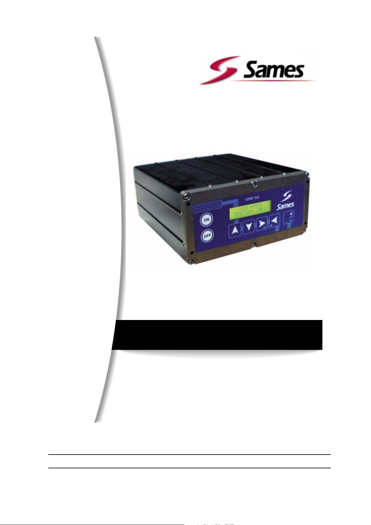
GNM 100 control module - 220V
FRANCE
USA
Index revision : C 1 6209
SAMES Technologies. 13 Chemin de Malacher 38243 Meylan Cedex
Tel. 33 (0)4 76 41 60 60 - Fax. 33 (0)4 76 41 60 90 - www.sames.com
SAMES Technologies Inc. 11998 Merriman Road, Livonia, Michigan, 48 150
Tel. (734) 261.5970 - Fax. (734) 261.5971 - www.sames.com
User manual
for manual guns
Page 2

Any communication or copying of this document, in any form whatsoever, and any use or divulging of its
contents is forbidden without express written permission from SAMES Technologies.
The descriptions and characteristics contained in this document may be changed without prior warning
and are in no way binding on SAMES Technologies.
© SAMES Technologies 2002
WARNING : Sames Technologies is registered as a "Training Center" approved by the "Ministry
of Employment".
Trainings with the aim of getting the necessary know-how to use and for the maintenance of your equipment can be organised all along the year.
A catalog is available upon request. Among the different training programmes proposed, you will be able to find the training which corresponds the best to your
needs and production purposes. These trainings can be organised in your premises
or in our training center based in our headquarters in Meylan.
Service formation :
Tel.: 33 (0)4 76 41 60 04
E-mail : [email protected]
Index revision : C 2 6209
Page 3

GNM 100 control module - 220V
1. Introduction - - - - - - - - - - - - - - - - - - - - - - - - - - - - - - - - - - - - - - - - - 4
2. Description - - - - - - - - - - - - - - - - - - - - - - - - - - - - - - - - - - - - - - - - - - 4
2.1. Presentation . . . . . . . . . . . . . . . . . . . . . . . . . . . . . . . . . . . . . . . 4
2.2. Specifications . . . . . . . . . . . . . . . . . . . . . . . . . . . . . . . . . . . . . . 5
2.2.1. Electrical input data . . . . . . . . . . . . . . . . . . . . . . . . . . . . . . . . . . . 5
2.2.2. Electrical output data . . . . . . . . . . . . . . . . . . . . . . . . . . . . . . . . . 5
2.2.3. Size . . . . . . . . . . . . . . . . . . . . . . . . . . . . . . . . . . . . . . . . . . . . . . . 5
3. Low voltage connections- - - - - - - - - - - - - - - - - - - - - - - - - - - - - - - - 6
3.1. Supply . . . . . . . . . . . . . . . . . . . . . . . . . . . . . . . . . . . . . . . . . . . . 6
3.2. Low voltage connectors . . . . . . . . . . . . . . . . . . . . . . . . . . . . . . . 6
3.3. Connecting plug (12 pins A) . . . . . . . . . . . . . . . . . . . . . . . . . . . 6
3.4. Connecting plug (7 pins C) . . . . . . . . . . . . . . . . . . . . . . . . . . . . 6
3.5. Connecting plug (19 pins B) . . . . . . . . . . . . . . . . . . . . . . . . . . . 7
3.5.1. Analog input. . . . . . . . . . . . . . . . . . . . . . . . . . . . . . . . . . . . . . . . . 8
3.5.2. Control of Vm and Im outputs . . . . . . . . . . . . . . . . . . . . . . . . . . . 8
3.5.3. Wiring of external trigger . . . . . . . . . . . . . . . . . . . . . . . . . . . . . . . 8
3.5.4. Using information relative to the faults. . . . . . . . . . . . . . . . . . . . 10
4. Operating principle of the GNM 100 - - - - - - - - - - - - - - - - - - - - - - - 11
4.1. Supply voltage and connections . . . . . . . . . . . . . . . . . . . . . . . 11
4.2. Automatic selection of the high voltage unit . . . . . . . . . . . . . . 11
4.3. Modifying a set point . . . . . . . . . . . . . . . . . . . . . . . . . . . . . . . . 11
4.4. Storing the set points . . . . . . . . . . . . . . . . . . . . . . . . . . . . . . . . 12
4.5. Using the values stored . . . . . . . . . . . . . . . . . . . . . . . . . . . . . . 12
4.6. Triggering the high voltage . . . . . . . . . . . . . . . . . . . . . . . . . . . 12
4.7. Faults . . . . . . . . . . . . . . . . . . . . . . . . . . . . . . . . . . . . . . . . . . . . 13
4.8. Cleaning the GNM 100 . . . . . . . . . . . . . . . . . . . . . . . . . . . . . . 13
5. Spare parts- - - - - - - - - - - - - - - - - - - - - - - - - - - - - - - - - - - - - - - - - 13
6. Plugs - - - - - - - - - - - - - - - - - - - - - - - - - - - - - - - - - - - - - - - - - - - - - 14
Index revision : 3
Page 4
1. Introduction
WARNING : Safety warning: the GNM 100 must never be installed in an explosive atmosphere.
This means it must be installed outside the coating booth at a minimum distance of 1.5 meters
(5 feet) from the nearest opening.
This control module is for the power units hereafter called the "high voltage units" which are fitted inside
the guns. This module is only for use with guns made by SAMES.
• The GNM module has a conductive extruded aluminium (black anodize) box, the tightness of
which conforms to protection index IP 64. Two part numbers are available:
• 858075 for all countries except the United Kingdom.
• 1516137 for the United Kingdom.
WARNING : For a use in cabinet, the room temperature must be below 45°C.
We strongly advise you not to place the GNM close to any source of heat, which would increase
its inner temperature and engender a working defect.
However, if the GNM has to be located in such conditions, provide for an air conditioning device.
The maximum temperature is 45°C for a use with a 90 KV/ 100µA high voltage unit (HVU). This
maximum temperature depends on the supplied power, therefore on the type of HVU/sprayer
which controls the GNM.
Storage temperature: 0°C to 70°C.
2. Description
2.1. Presentation
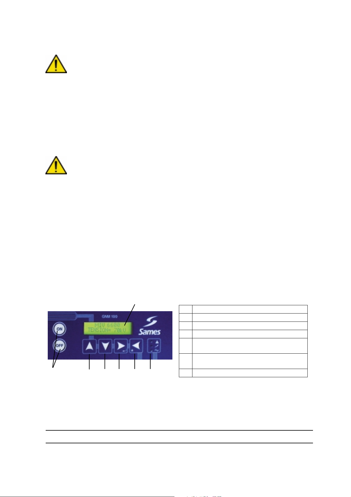
The GNM 100 has a microcontroller which displays the functions on a two-line screen.
1
1 Display
2 Signal lights (3 leds).
3 Last screen / special function (*).
4 Next screen or validation of a value.
5 To decrease parameter values and select
preselected settings.
6 To increase parameter values and select
preselected settings.
7
(*) : the other functions are described further on in this manual.
Signal lights:
• green = GNM 100 powered.
• orange= trigger (high voltage activated).
• red = fault.
5
6
3
4
2
7 ON / OFF switch.
Index revision : C 4 6209
Page 5
2.2. Specifications
Working temperature: 0 to 40° C (32 to 104°F)
2.2.1. Electrical input data
Input voltage 220 VAC + / - 20 V
Frequency 50 / 60 Hz
Maximum input power 50 VA
2.2.2. Electrical output data
Maximum voltage output 60 V RMS
Frequency output 16-60 kHz
Maximum output current 1,1 A RMS
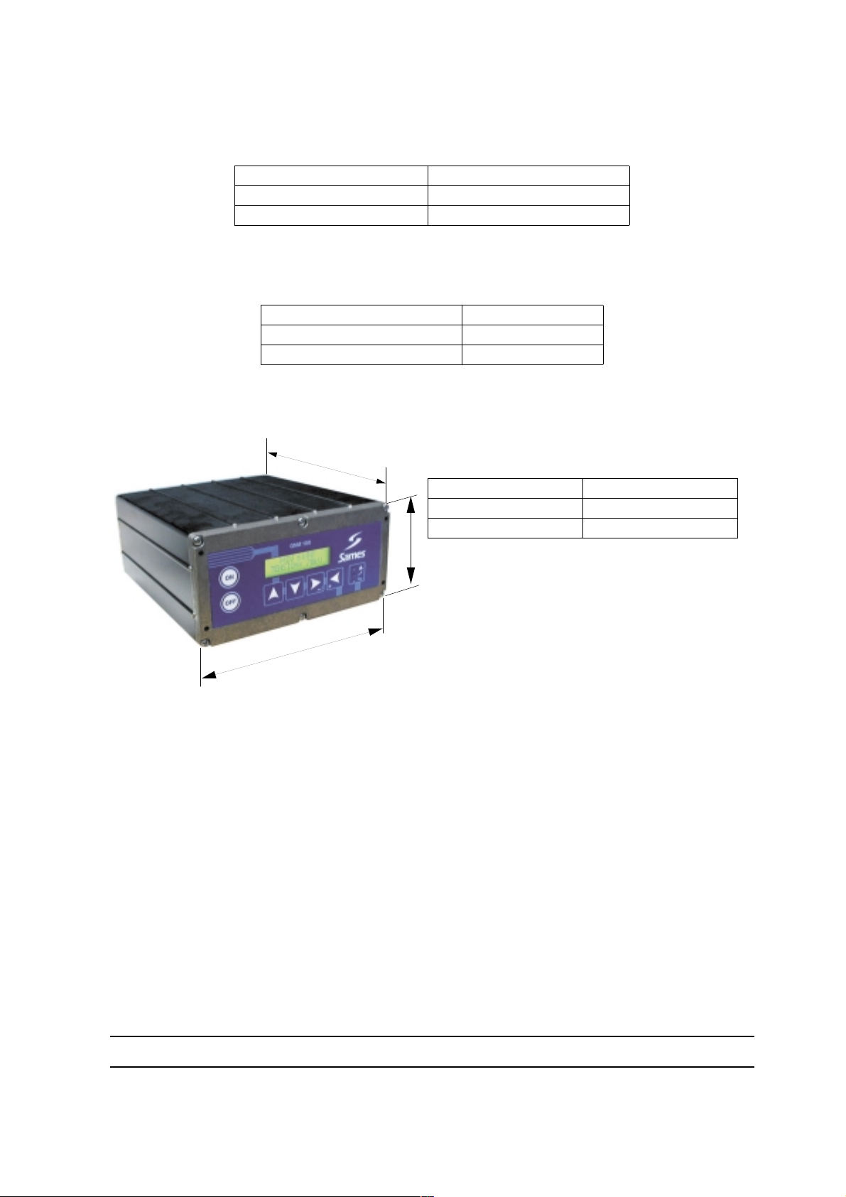
2.2.3. Size
230 mm
GNM 100
Protection index: IP 64
Mass with cable 3 kg - 6.6 lbm
175 mm
85 mm
DES00433
Index revision : C 5 6209
Page 6
3. Low voltage connections
3.1. Supply
The GNM can be supplied with 220 V or 110 V voltage, 50-60 Hz. Selection takes place by means of a
switch located on the main printed circuit.
3.2. Low voltage connectors
WARNING : see RT Nr 6169 for use with a high voltage unit UHT 153.
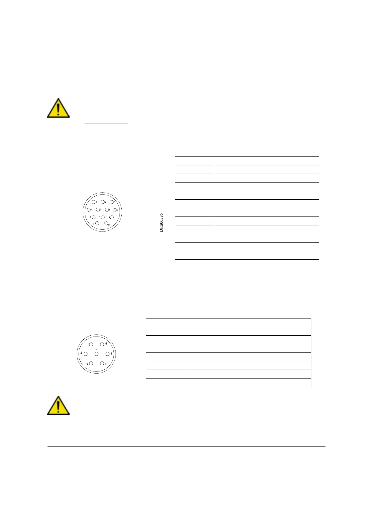
3.3. Connecting plug (12 pins A)
Connection to the high voltage unit.
N° of pins Signal
1 earth
2 input + photo coupler
3 + 15 V
4 earth
5 input + photo coupler
6 high voltage unit recognition
7 high voltage unit recognition (earth)
8 shielding
9 high voltage unit transformer
10 high voltage unit transformer
11 return I HV
12 return U HV
3.4. Connecting plug (7 pins C)
Connection to the controls of the atomizer (e.g. electro valve). It is possible to use the 4, 5 and 6-pins
(trigger copy for the PLC).
N° of pins Signal
1 earth
2 phase 1, output protected
3 phase 2, output protected
4 common to trigger image relay
5 trigger image relay contact normally closed
6 trigger image relay contact normally open
7 not connected
WARNING : This relay is for passing low currents. If a high current is used this contact can no
longer be used for low currents.
Index revision : C 6 6209
Page 7
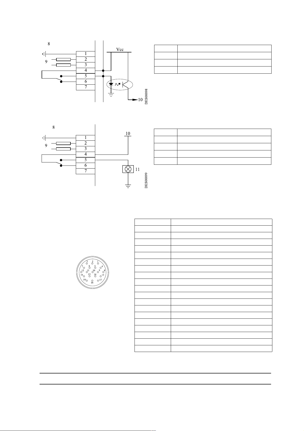
Example of a PLC cabling:
Cabling for "HV ON" signalling light,
1 to 7 GNM case
8 Inside GNM
9 Main supply output protected by fuses
10 PLC input
1 to 7 GNM case
8 Inside GNM
9 Main supply output protected by fuses
10 220 VAC oR 110 VAC
11 Light on
3.5. Connecting plug (19 pins B)
Connection to an PLC:
N° of pins Signal
1 Earth
2 Not connected
3 Not connected
4 Input 4 / 20 mA
5 Earth 4 / 20 mA or 0 / 10 V
6 Input 0 / 10 V
7 Image output Vm (100 kV = ~ 5 V)
8 Earth
9 Image output Im (500 µA = ~ 5 V)
10 Input + photo coupler
11 + 15 V / 50 mA max. protected
12 Earth
13 Input + photo coupler
14 Relay OK board contact normally closed
15 Relay OK board contact normally open
16 OK board common relay
17 Not connected
18 Not connected
19 Not connected
The mass is joined to the earth through the board.
Index revision : C 7 6209
Page 8
3.5.1. Analog input
Cabling on external adjustment points can be 4/20 mA or 0-10 V.
3.5.1.1. 4/20 mA adjustment point
This scale setting has to be done in a PLC. To do this, apply an adjustment point of 8 mA and another
adjustment point of 16 mA and read the HV value on the GNM screen. A simple calculation permits one
to fine the corresponding point.
3.5.1.2. 0/10 V adjustment point
Scale setting is done inside the GNM .
10 V corresponds to 100 kV . For a high voltage unit on which the maximum voltage is below 100 kV , the
adjustment point is automatically reveled at its maximum value.
3.5.2. Control of Vm and Im outputs
Copies of Vm and Im are only given as indications. They are not calibrated inside the GNM and differences can exist.
3.5.2.1. Control of the Vm output
The Vm scale is 0-5 V for 0-100 kV . The minimum impedance of the measure equipment has to be 50
k Ω .
3.5.2.2. Control of the Im output
The Im scale is 0-5 V for 0-500 µA.
The minimum impedance of the measure equipment has to be 50 k Ω
.
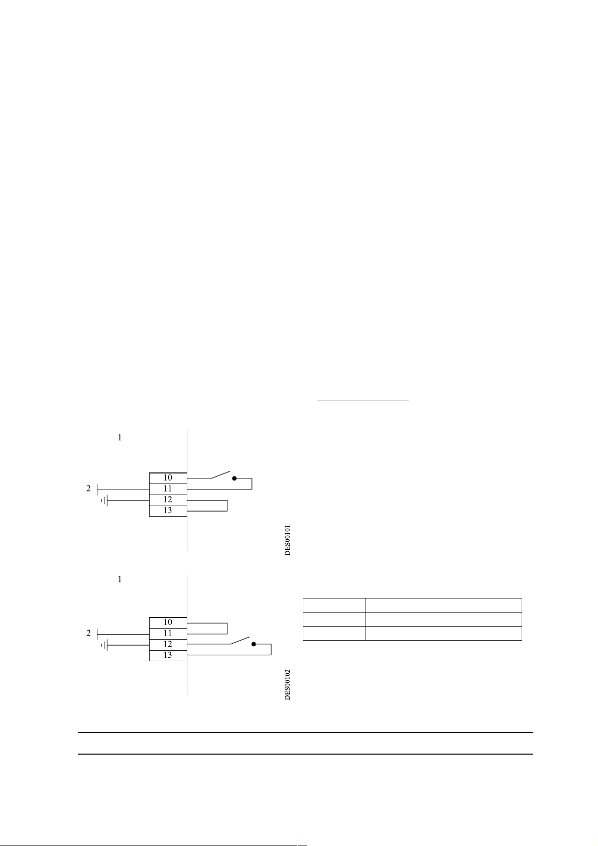
3.5.3. Wiring of external trigger
Control of the external trigger can be done in two ways:
• Dry contact,
• Using external voltage between 12 and 24 Vdc (see § 3.5.3.2 page 9).
3.5.3.1. Dry contact. There are two possibilities:
or :
1 Inside GNM
2 + 15 Vdc; 50 mA max
10 to 13 GNM case
Index revision : C 8 6209
Page 9
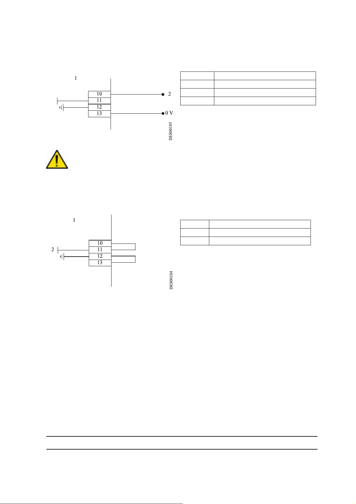
3.5.3.2. Using external voltage
The external voltage is between 12 and 24 Vdc.
Input impedance roughly 1 k Ω .
0 V Supply return 12 to 24 V
1 Inside GNM
2 + 12 to 24 V dc
10 to 13 GNM case
WARNING : Inputs 10 and 13 are opto-coupled inputs. They are therefore isolated from the earth.
Make sure that the 0 V of the 12 to 24 V supply is at a potential close to the earth.
3.5.3.3. In the case where P8 = 1,
The trigger has to be connected as follows:
1 Inside GNM
2 + 15 Vdc; 50 mA max
10 to 13 GNM case
Index revision : C 9 6209
Page 10
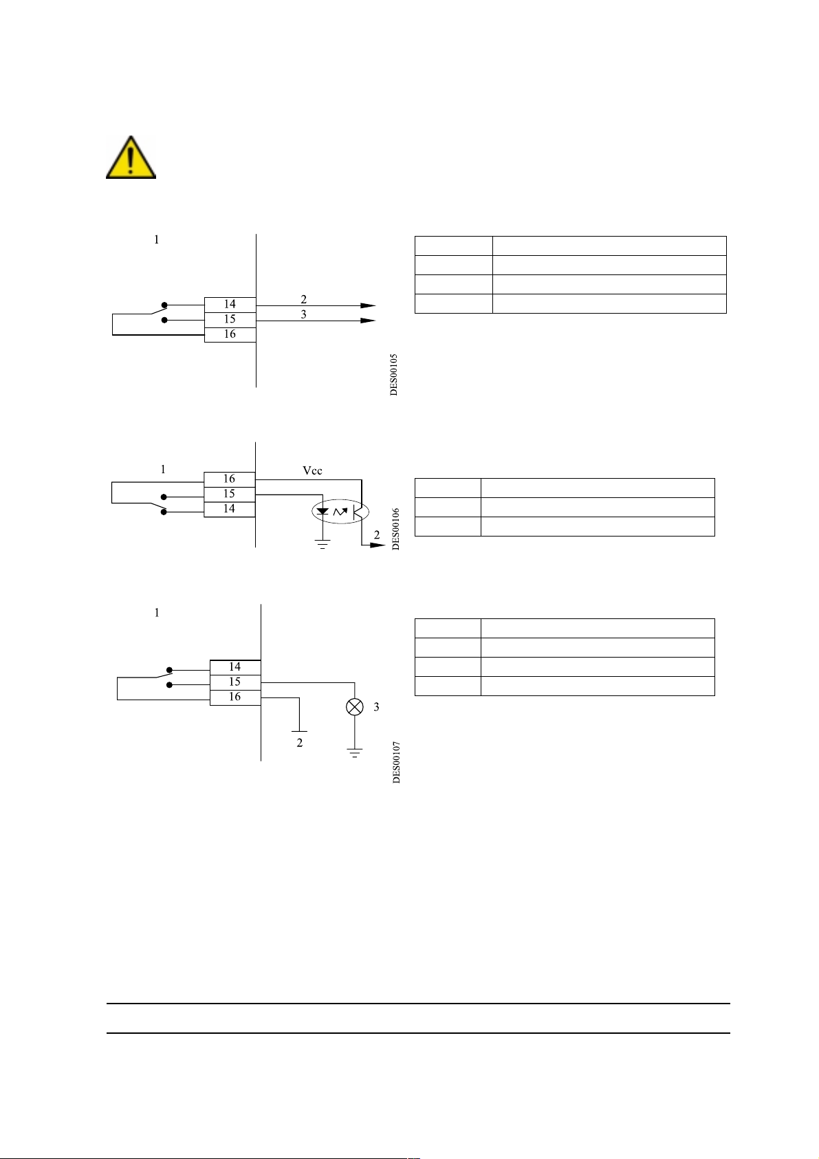
3.5.4. Using information relative to the faults
The closed contact of the OK board relay signals that the board is under voltage and that there is no fault.
WARNING : This relay is for passing low currents. If a high current is used this contact can no
longer be used for low currents.
1 Inside GNM
2 OK board
3 No OK board
14 to 16 GNM case
Liaison wiring with an PLC:
1 Inside GNM
2 PLC input
14 to 16 GNM case
Wiring of a HV fault signalling lamp:
1 Inside GNM
2 220 VAC oR 110 VAC
3 Fault
14 to 16 GNM case
Index revision : C 10 6209
Page 11
4. Operating principle of the GNM 100
4.1. Supply voltage and connections
The voltage of the GNM 100 is preset at 220 V. Make sure that the earth terminal of the module (located
at the back) is property connected to the earth with cable with a gauge between 6 and 10 mm2. Connect
the mains cord. Connect the gun plug to the GNM 100 (marked A on the back of the box).
WARNING : The messages indicated are given as guidelines and vary according to the type of
gun used.
4.2. Automatic selection of the high voltage unit
WARNING : Each time a new type of high voltage unit is validated, all the parameters take the
works preset value and the old parameters are replaced by the new ones.
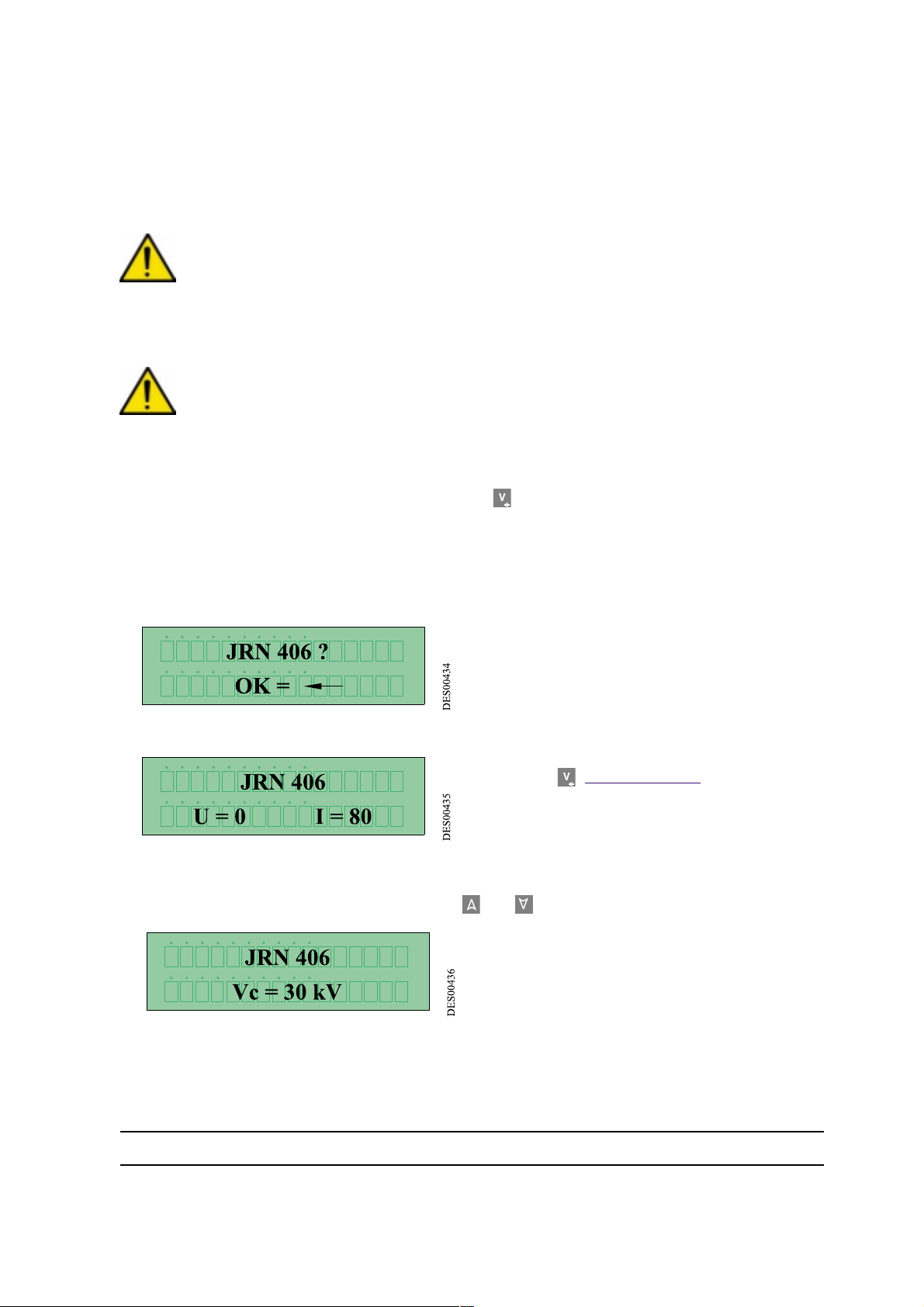
When connected to a different type of high voltage unit, the GNM message will request validation of this
new high voltage unit which is done by pressing key 4 .
When connected to a high voltage unit, the GNM 100 automatically recognises it and displays its name
on the screen. If it is the same as the one used the last time, the following screen will not appear.
If the display indicates a type of gun other than the one connected, do not validate. Switch off the GNM
100 and disconnect the gun. Connect the gun again and try to power the GNM 100 again.
If the gun is still not recognised by the GNM 100, contact a SAMES distributor.
After validation, the display indicates:
•U = 0 (high voltage set point)
•I = 80 (current limitation set point).
Press key 4 (see § 2.1 page 4).
4.3. Modifying a set point
To change the high voltage set point, press key 2 or 3 . The display will, for example, indicate:
Press V to scroll the menu.
Index revision : C 11 6209
Page 12
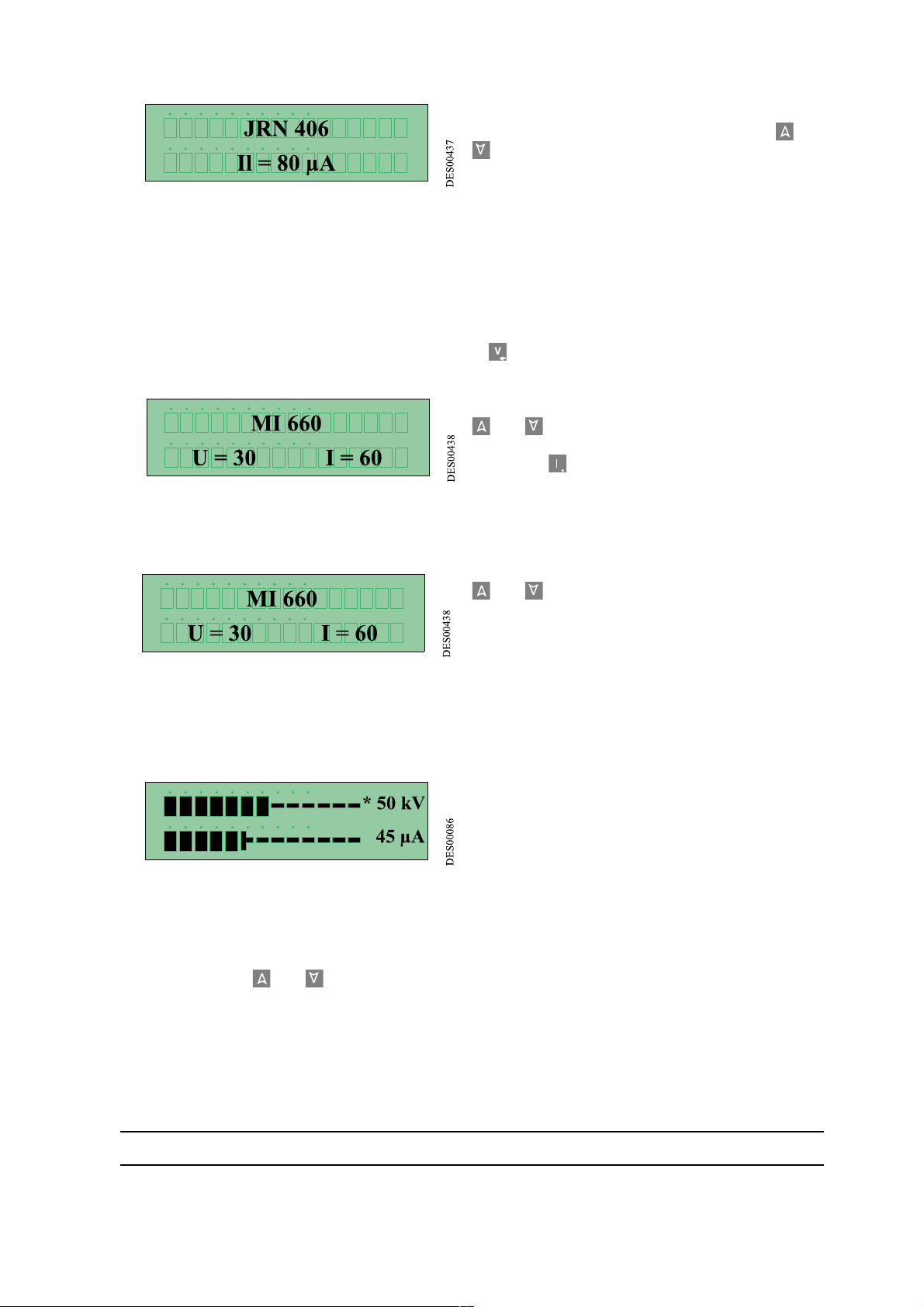
To change the current set point, press key 2 or 3
. The display will, for example, indicate:
4.4. Storing the set points
The GNM 100 can memorise 9 U and I value tables preset by the user as needed. These tables are referenced from J1 to J9.
To create a table:
• The gun trigger must be released.
• Adjust the high voltage (Vc) and the current limitation (Il) set point values according to the proce-
dure described in paragraph3.3, then press key .
the display will, for example, indicate:
•Choose a table (from J1 to J9) by pressing keys 2
or 3 (for example J2).
•Press key for three seconds. The U and I values
are stored in the table J2.
4.5. Using the values stored
When, for example, the display indicates:
Choose a table (from J1 to J9) by pressing keys 2
or 3 .
The set point values of the high voltage and the current limitation used are memorised in the table chosen.
4.6. Triggering the high voltage
The trigger has to be puller for the gun to be powered.
The display takes the form of a bar graph, indicating the high voltage and current values, for example:
Displayed at the end of each bar graph is the voltage value at the gun electrode (in kilovolts) and the
current debited by the gun's high voltage electrode
(in micro amps).
The position of the symbol (*) at the end of the bar graph indicates whether the module works by a high
voltage regulation or by a current limitation.
If no table is used when the trigger is pulled, the high voltage and current set point values can be modified
by pressing keys 2 or 3 .
If a table from J1 to J9 is used when the trigger is pulled, the values cannot be changed.
When the trigger is released for more than 3 seconds, the last value read is displayed.
Index revision : C 12 6209
Page 13
4.7. Faults
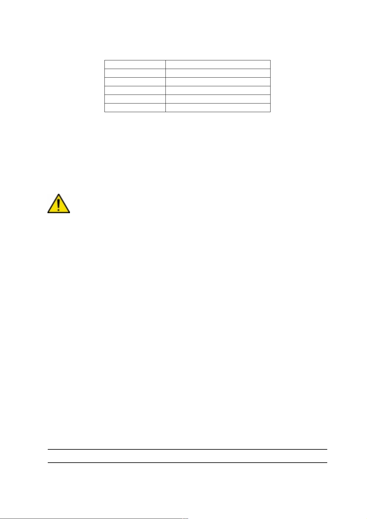
Six "major" faults can be displayed on the GNM 100
Fault tempeture Excessive casing temperature
Fault UP High voltage unit not recognised
Fault CC Low voltage output short circuit
Fault Reg. Freq Bad frequency regulation
Fault µP Micro calculator fault
Fault Supply Bad internal supply regulation
The faults are displayed in code on the two display lines and the red signal light lights up.
The only way to reset the faults is to turn off the module for a minimum of 30 seconds and to put it on
again by means of the push button (7).
The GNM 100 has a safety sector which removes the display messages when activated.
To reset, turn power off (7). Wait one minute and turn on again (7).
4.8. Cleaning the GNM 100
WARNING : turn off the GNM 100 control module before cleaning
To clean paint from the front of the GNM 100, use a rag dipped (and not soaked) in ethyl alcohol or
burning alcohol.
Note: Do not use a solvent or a thinner.
Dry immediately with a clean cloth.
5. Spare parts
As this module is sealed, only «SAMES Technologies» is authorised to carry out repairs.
Index revision : C 13 6209
Page 14
6. Plugs
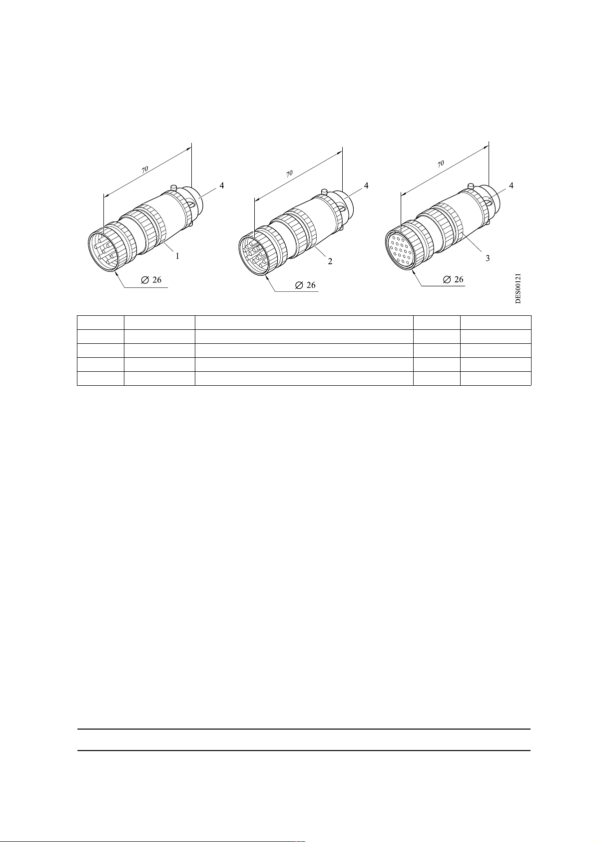
Ref. Part number Description Qty Sale unit
1 E4PTFS316 Male plug 7 contacts 1 1
2 E4PTFS343 Male plug 12 contacts 1 1
3 E4PTFS406 Female plug 19 contacts 1 1
4 E4PTFA323 Cable clamp 1 1
Index revision : C 14 6209
 Loading...