

Page 1
Index revision : A 1 7087_S
User manual
SAMES Technologies. 13 Chemin de Malacher 38243 Meylan Cedex
Tel. 33 (0)4 76 41 60 60 - Fax. 33 (0)4 76 41 60 90 - www.sames.com
E-SERIES
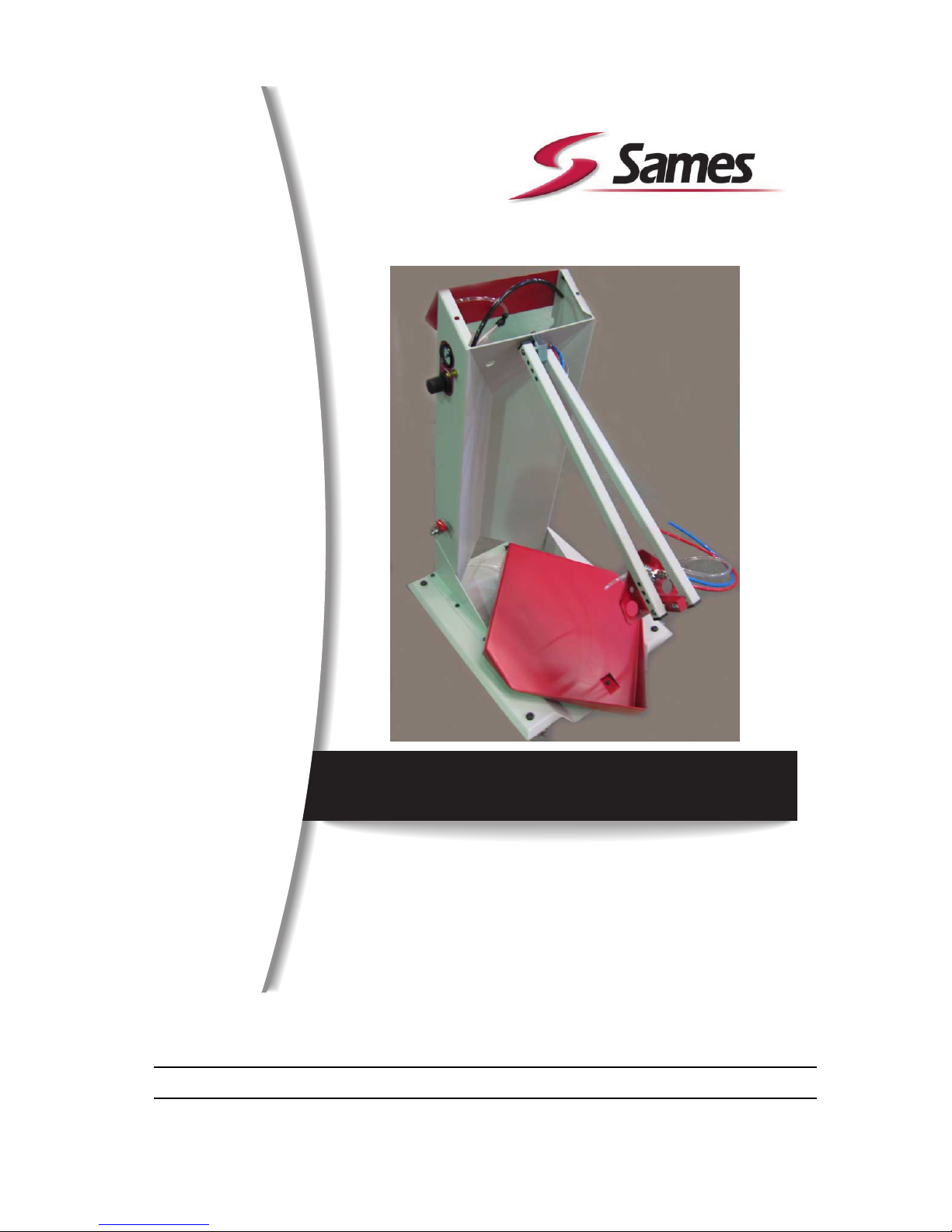
Cart with vibrating table
Page 2

Index revision : A 2 7087_S
All communication or reproduction of this document, in any form whatsoever and all use or
communication of its contents are forbidden without express written authorisation from
SAMES Technologies.
The descriptions and characteristics mentioned in this document are subject to change without prior
notice.
© SAMES Technologies 2010
WARNING : SAS Sames Technologies is registered with the Ministry of Labour as a training
institution.
Throughout the year, our company offers training courses in the operation and
maintenance of your equipment.
A catalogue is available on request. Choose from a wide range of courses to
acquire the skills or knowledge that is required to match your production
requirements and objectives.
Our training courses can be delivered at your site or in the training centre at our
Meylan head office.
Training department:
Tel. 33 (0)4 76 41 60 04
E-mail: [email protected]
SAS Sames Technologies operating manuals are written in French and translated into English, German, Spanish, Italian and
Portuguese.
The French version is deemed the official text and Sames will not be liable for the translations into other languages.
Page 3

Index revision : 3
E-SERIES
Cart with vibrating table
1. Health and safety instructions- - - - - - - - - - - - - - - - - - - - - - - - - - - - - 4
2. Description - - - - - - - - - - - - - - - - - - - - - - - - - - - - - - - - - - - - - - - - - - 5
2.1. General presentation . . . . . . . . . . . . . . . . . . . . . . . . . . . . . . . . . 5
2.1.1. Vibrating table . . . . . . . . . . . . . . . . . . . . . . . . . . . . . . . . . . . . . . . 5
2.1.2. Support arm for powder pump. . . . . . . . . . . . . . . . . . . . . . . . . . . 5
2.1.3. Control panel . . . . . . . . . . . . . . . . . . . . . . . . . . . . . . . . . . . . . . . . 5
3. Characteristics - - - - - - - - - - - - - - - - - - - - - - - - - - - - - - - - - - - - - - - 6
3.1. General characteristics . . . . . . . . . . . . . . . . . . . . . . . . . . . . . . . 6
3.2. Pneumatic characteristics . . . . . . . . . . . . . . . . . . . . . . . . . . . . . 6
4. Operation - - - - - - - - - - - - - - - - - - - - - - - - - - - - - - - - - - - - - - - - - - - 6
5. Tools - - - - - - - - - - - - - - - - - - - - - - - - - - - - - - - - - - - - - - - - - - - - - - 6
6. Installation - - - - - - - - - - - - - - - - - - - - - - - - - - - - - - - - - - - - - - - - - - 7
6.1. Set up procedure . . . . . . . . . . . . . . . . . . . . . . . . . . . . . . . . . . . . 8
7. Troubleshootings - - - - - - - - - - - - - - - - - - - - - - - - - - - - - - - - - - - - - 8
8. Spare parts- - - - - - - - - - - - - - - - - - - - - - - - - - - - - - - - - - - - - - - - - - 9
Page 4

Index revision : A 4 7087_S
1. Health and safety instructions
WARNING : This manual contains links to the following user manual
• see RT Nr 7079_S for MG 400-AG 400 spray guns and CGU 400 control module.
Note: This device complies with the ATEX directive. It may be dangerous if it is not used in compliance with the safety regulations specified in this manual.
WARNING : This cart is intended for use with powder-paint spraying apparatus only (MG 400
manual spray gun and AG 400 automatic spray gun).
• This device must only be used by personnel trained and accredited by SAMES Technologies.
Operating staff must first read the user manual and the user manuals for any peripheral electrical
equipment present in the spraying area. The workshop manager must ensure this is the case.
• The cart must always be installed and used in areas where there is no risk of explosion.
• It is essential to connect the bonding strip under the vibrating table and to connect the CGU 400
control module to the ground to guarantee the safety of operators and correct operation of the
powder-coating equipment.
• When a vibrating table is used, the plastic bag containing the powder must be tightly wrapped
around the plunger tube to avoid any escape of powder, which could create an explosive atmosphere.
• The box must be filled in a ventilated area designed for the purpose and under no circumstances
anywhere near the cart.
• Under no circumstances may the cart be used to carry or transport loads other than the powder
tank or a powder box with a maximum weight of 30 kg on the vibrating table.
• Ambient temperature must not exceed 40 °C (104°F).
• The spraying area must be kept clean and clear of any unnecessary items.
• The floor on which the operator works must be anti-static (bare concrete or metal duckboard).
Never use an insulating floor covering.
• Powder spraying must be carried out in front of a ventilated booth designed for the purpose. Startup of the CGU 400 control module must be interlocked with operation of the ventilation system.
• Skin-contact with or inhalation of products used with this equipment may be dangerous for
personnel (cf.: Safety sheets for products used).
• The parts to be painted must have a resistance with respect to ground that is less than or equal to
1M
Ω
.
• Powder-spraying equipment must be maintained regularly according to the instructions laid out in
this manual.
• Only genuine Sames Technologies spare parts can guarantee operating safety for the equipment.
• Genuine SAMES hoses must be used to connect the powder pump.
Page 5
Index revision : A 5 7087_S
2. Description
2.1. General presentation
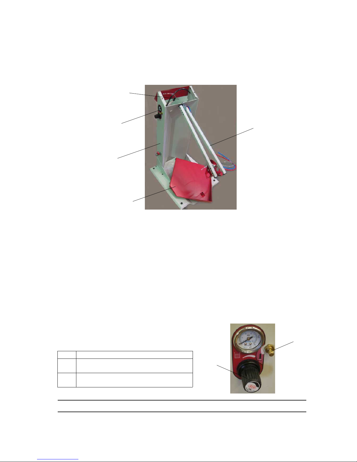
The convenient, compact size of the cart makes it easy to manoeuvre and move, with four
freely-steerable wheels. The MG 400 manual spray gun is fixed to the cart by a hook. The cart also
includes the CGU 400 control module.
2.1.1. Vibrating table
This component enables standard powder boxes of up to 30 kg to be easily used.
It is fitted on the cart at a slight angle, in order to ensure the powder is fully taken up, even from the bottom of the box.
A high-performance pneumatic vibrator is used to vibrate the powder and minimise compaction. Vibration frequency can be adjusted according to the type of powder used and level of product remaining.
Vibrator operation is activated with the spray gun trigger.
2.1.2. Support arm for powder pump
Integrated into the cart, it supports one or two powder pumps. It ensures a correct positioning in the powder box.
Gradually, the tube of the powder pump slides at the same time as the level of powder comes down in
the box.
In order to facilitate the replacement of the powder box, the arm is locked in a high position releasing
sufficient space.
2.1.3. Control panel
Item Function
1
Vibrator air supply pressure adjustment and
reading (for vibrating table)
2
Fluidisation air flow-rate adjustment (plunger
tube)
Support arm for
powder pump
Cart
Vibrating table
Control panel
Location for
CGU 400 control
module
2
1
Page 6
Index revision : A 6 7087_S
3. Characteristics
3.1. General characteristics
Because of the structure of the cart:
• a box with a weight of approximately 30 kg (66 lb) and with maxi. dimensions of 430 x 430 x 430
of powder can be placed on a vibrating table.
3.2. Pneumatic characteristics
Characteristics of the compressed-air supply according to standard NF ISO 8573-1:
* : Air flow-rate values are given for a temperature of 20° C (68 °F) at an atmospheric pressure of
1013 mbar.
Powder maximum flow-rate: variable until 500g/min
“Fluidisation” air: until 4 bar (58,8 psi) max.
4. Operation
The powdered paint remains in its original box. The box is placed on the vibrating table.
The vibrator vibrates the table and enables the fluidisation head to reach the bottom of the powder box.
The fluidisation nozzle, with its compressed air supply, “fluidises” the powdered paint.
The powdered paint, fluidised in this way, is then carried by an air jet from the powder pump to the spray
gun to which it is connected by a powder-carrying hose.
5. Tools
No specific tools.
Cart dimensions (h x w x d) 1080 x 450 x 620 mm
Approximate weight (without powder) 40 kg.
Operating temperature from 0°C to 40°C (32°F to 104°F).
Maximum dew point at 6 bar (87 psi) class 4, i.e. + 3 °C (37 ° F)
Maximum particle size of solid contaminants Class 3, i.e. 5 µm.
Maximum oil concentration
Class 1, i.e. 0.01 mg/m
0
3
*
Maximum concentration of solid contaminants
5 mg / m
0
3
*
Cart air supply pressure 7 bar max (101.5 psi)
Page 7

Index revision : A 7 7087_S
6. Installation
WARNING : This equipment must be imperatively connected to the ground.
• Carefully remove units and components from packaging, and check contents against packing list.
• Install the cart in a secure manner and placed at least 1,5 m of any opening of the booth (see RT
Nr 7079_S ). Secure the CGU 400 control module on the cart using the two M6 x 10 screws and
the two locking washers with a 5mm allen wrench.
• Connect the airlines to the outlet ports of the rear panel of the Gun Control Unit as follows : (see
RT Nr 7079_S for the rear panel illustration and key to symbols).
1 Red airline from Venturi Jet to the 'Powder Delivery Air Supply Output'.
2 Blue airline from Venturi Dilution Port to the 'Powder Dilution Air Supply Output'.
3 Black airline from the Guns to the 'Gun Air Supply Output'.
Equipment with vibrating table, connect the colorless airlines from the vibration control regula-
tor and the Fluidising Pad (which are joined with a “T” connector) to the ‘Vibrating Box Air Supply
Output’ at the top right hand corner of the control unit.
NOTE: The powder pump is identified by a Red washer & the Dilution Port by a Blue washer.
• Connect the black airline (Dia: 8mm) to the centre right hand air fitting on the rear of the gun control
module (see RT Nr 7079_S
).
• Insert the suction tube on the front bracket of the articulated arm until it latches into position.
• Ensure that the three airlines which exit the front of the articulated arm are connected as follows:
1 Red airline to ”Powder delivery” air fitting at the top rear of the powder pump (the sealing
washer of this fitting is red).
2 Blue airline to ”Powder dilution” air fitting at the top centre of the powder pump (the sealing
washer of this fitting is blue).
3 Black airline to the ”Fluidising pad” coupling fitting on the top of the powder pump mounting
bracket.
• Secure the gun hook to the side of the cart using the M 6x 50 socket cap head screw.
• Connect the powder hose to the powder pump.
• Connect an air supply hose to the ball valve mounted on the side of the cart.
Page 8

Index revision : A 8 7087_S
6.1. Set up procedure
•
Step 1 : Ensure that all switches are in the OFF position and that all pressure regulators are closed,
(the knobs should be turned fully anti-clockwise). The knob of the pressure regulators are unlocked
by pulling outwards and locked by pressing inwards.
• Step 2: Lift the articulated arm to its maximum height and push down on the front of the powder
pump support brack to lock the arm into a parked position.
• Step 3 : Place an open box of powder onto the vibrating table.
• Step 4 : Lift the front of the powder pump support bracket and lower the articulated arm and suction
tube so that the fluidized suction head is lowered onto the powder. The tube enters the powder
during the application and digs into the powder towards the front corner of the box.
• Step 5 : Turn on the ”Mains Electrical” (third on the right) switch of the control module to the position
marked The numerical display of set value and the mode indicator lights.
High voltage is enabled.
• Step 6 : In the spraying booth, press the trigger of the spray gun. A red LED lights next to the ”T”
symbol on the display.
• Step 7 : With the trigger still pressed, open the flow regulator to approximately 2 bars (29.4 psi) on
the side of the cart. Then open the flow adjuster by turning the knob anti-clockwise until a slight
disturbance of powder is noticed around the fluidizing pad at the bottom of the suction tube. This
air supply should be kept to a minimum consistent with smooth powder flow to prevent powder from
being ejected from the box into the surrounding air.
The flow adjuster, equipped with a lock nut, may be used to lock the fluidisation setting.
To set up the spraying: see RT Nr 7079_S.
7. Troubleshootings
see RT Nr 7079_S
Page 9
Index revision : A 9 7087_S
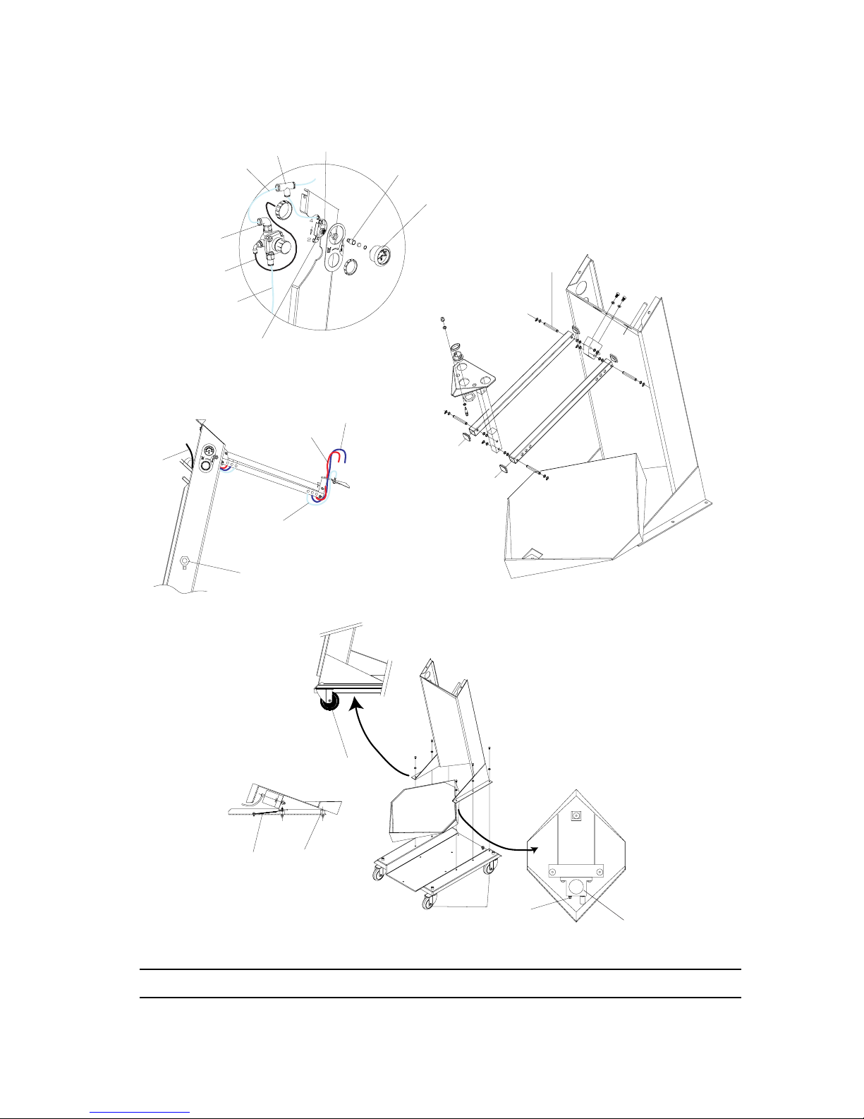
8. Spare parts
DES05017
1
2
3
4
5
6
7
8
9
10
11
12
13
9
9
14
15
16
17
18
19
Page 10
Index revision : A 10 7087_S
(*)
Level 1: Standard preventive maintenance
Level 2: Corrective maintenance
Level 3: Exceptional maintenance
Item Part Number Description Qty
Sale
Unit
Spare Part
Level
(*)
EU75009004S E-Series Cart with vibrating table 1 1 3
1 EU5009010 Pivot axle 4 1 3
2 EU9001031 Pneumatic vibrator 1 1 2
3 EU9000105 Male straight union 1/4 D6 1 1 3
4 EU9000065 Rubber pivoting roller - Dia:75 3 1 3
5 EU9000064 Conductive rubber pivoting roller Dia:75 1 1 3
6 EU9000355 Damper 1 1 3
7
EU9001064 Bonding strip - 30A 1 1 3
E4CSPR085 Blue lug - Dia: 6 1 1 3
8 EU9001892 Mini Ball valve 1/4 1 1 3
9 EU9000170 Colorless polyurethane 4x6 hose 2,5 m 3
10 U1GLBT152 Blue polyurethane 4x6 hose
1,25
m3
11 U1GRBW198 Red polyurethane 4x6 hose
1,25
m3
12 EU9000171 Black polyurethane 5.5x8 hose
0,75
m3
13 F6RLCS508 Cylindrical male union bracket M5 D6 1 1 3
14 EU9000203 Black polyurethane 2.5x4 hose
0,25
m3
15 EU75009007 Regulator 4 bar 1 1 3
16 F6RLTS485 Equal Tee Dia: 6 1 1 3
17 EU9000363 Flow adjuster 1 1 3
18 EU9000052 Female straight union 1/8 D4 1 1 3
19 EU9001879 Pressure gauge (4 bar) 1 1 3
 Loading...