


SAM Electronics NG3028X25KW, NG3029S30KW Users Manual

Operating Instructions
RADARPILOT ATLAS 1000
CHARTRADAR ATLAS 1000
MULTIPILOT ATLAS 1000
Software Version 2.4
Radar Functions
Plotting Aids
Item No.: ED 3038 G 232 Revision: 01 (2002-06) Order No.: 300004937

This document is our property for which we reserve all rights, including
those relating to patents or registered designs. It must not be
reproduced or used otherwise or made available to any third party without
our prior permission in writing.
Alterations due to technical progress are reserved.
STN ATLAS Marine Electronics GmbH
D - 22763 Hamburg
Service
Customer Support Center
Phone: + 49 (0) 18 03 00 85 53
Fax: + 49 (0) 18 03 00 85 54
E-mail: shipservice@sam-electronics.de
b_r1_eti.fm / 21.06.02

RADARPILOT / CHARTRADAR
Operating Instructions
General Safety Precautions
General Safety Precautions
Particular attention must be paid to the notes and warnings referring to possible faults in the radar display, since such faults can
impair the detection of targets.
The radar can perform its safety function if, and only if, the transmission power and the receiver sensitivity
are adequate. Therefore, these characteristics must be checked regularly (by means of the Performance
Monitor – see Section 21).
Connected position receivers must fulfil the standard IEC 61162-1
ARPA target data are directly dependent upon the accuracy and proper functioning of the selected speed
sensor and the gyro compass.
1)
.
DANGER: High frequency radiation
Persons must definitely avoid being present in the radiation danger zone
of the rotating antenna.
In the case of work being done on the antenna unit, the antenna switch
situated there must be set to
0 and the transceiver must be discon-
nected from the ship’s mains.
☞ There is no international agreement about the danger posed by high frequency radiation of the kind
produced by the radar systems. In most countries, a radiation density exceeding 100 W/m
ered to be dangerous; in some countries, values over 10 W/m
2
are regarded as not being completely
2
is consid-
safe.
Antenna Type
5 ft X-Band
8 ft X-Band 12.5 kW, Version A 0.65 m 7 m
14 ft S-Band
Transceiver
A=Up B=Down
12.5 kW, Version A 1.4 m 14 m
25 kW, Version B 1.65 m 16 m
30 kW, Version A 1.3 m 13 m
30 kW, Version B 0.7 m 7.8 m
Radius of the Radiation Danger Zone
Radiation Density
100 W/m
2
Radiation Density
10 W/m
2
1)
IEC 61162-1 largely corresponds to NMEA 0183 Version 2.30 of 1st March 1998.
ED 3038 G 232 / 01 (2002-06)
b_r1_esh.fm / 21.06.02
3

General Safety Precautions
DANGER: Injury caused by a rotating antenna
When the radar system is switched to "ON", it is possible that, instead
of the expected antenna, a different one will begin to rotate. Therefore, it
must be ensured beforehand that all antennas can rotate freely and that
are no persons near the antennas.
The units may be opened only by qualified, trained persons.
DANGER: Dangerous voltage
Even when the equipment is switched off, there can be a dangerous
voltage present at exposed contacts in the units. Therefore, before a unit
is opened, it must be ensured that the voltage supply to the unit is
disconnected from the ship’s mains, and that it remains disconnected.
Because of the capacitors contained in the units, there can be a
dangerous voltage present in any unit even several minutes (or several
hours in the case of monitors) after switching off and disconnection
from the power supply.
RADARPILOT / CHARTRADAR
Operating Instructions
☞ If the units are to be disconnected from the ship’s mains, it must be remembered that each antenna
unit, each transceiver electronics unit and each indicator normally has its own supply of power from
the ship’s mains.
If, for the transfer of signals (e.g. transfer of the heading signal from the compass system), synchro
transmitter are used, a dangerous voltage exists in the units until the reference voltage is switched
off.
4
ED 3038 G 232 / 01 (2002-06)
b_r1_esh.fm / 21.06.02

RADARPILOT / CHARTRADAR
Operating Instructions
List of Contents
List of Contents
Please pay attention to the supplement (if any) at the end of the document.
☞
General Safety Precautions . . . . . . . . . . . . . . . . . . . . . . . . . . . . . . . . . . . . . . . . . . . . . . . . . . . . 3
List of Contents . . . . . . . . . . . . . . . . . . . . . . . . . . . . . . . . . . . . . . . . . . . . . . . . . . . . . . . . . . . . . 5
1Overview . . . . . . . . . . . . . . . . . . . . . . . . . . . . . . . . . . . . . . . . . . . . . . . . . . . . . . . . . . . . . . . . . . . . 9
1.1 RADARPILOT ATLAS 1000 . . . . . . . . . . . . . . . . . . . . . . . . . . . . . . . . . . . . . . . . . . . . . . . . . . . . 9
1.2 CHARTRADAR ATLAS 1000 . . . . . . . . . . . . . . . . . . . . . . . . . . . . . . . . . . . . . . . . . . . . . . . . . . . 9
1.3 MULTIPILOT ATLAS 1000 . . . . . . . . . . . . . . . . . . . . . . . . . . . . . . . . . . . . . . . . . . . . . . . . . . . . 10
1.4 The Equipment Components . . . . . . . . . . . . . . . . . . . . . . . . . . . . . . . . . . . . . . . . . . . . . . . . . 10
1.5 Scope of Applicability of these Operating Instructions . . . . . . . . . . . . . . . . . . . . . . . . . . . 11
2 Basic Settings; General Remarks about Operating . . . . . . . . . . . . . . . . . . . . . . . . . 15
2.1 Switching the Radar System On and Off . . . . . . . . . . . . . . . . . . . . . . . . . . . . . . . . . . . . . . . 15
2.2 General Remarks about the Operating and Display Elements . . . . . . . . . . . . . . . . . . . . . . 16
2.3 Brilliance and Colour Selection . . . . . . . . . . . . . . . . . . . . . . . . . . . . . . . . . . . . . . . . . . . . . . . 21
2.4 Degaussing . . . . . . . . . . . . . . . . . . . . . . . . . . . . . . . . . . . . . . . . . . . . . . . . . . . . . . . . . . . . . . . . 23
2.5 Display Modes . . . . . . . . . . . . . . . . . . . . . . . . . . . . . . . . . . . . . . . . . . . . . . . . . . . . . . . . . . . . . 24
2.6 An Overview of the Screen . . . . . . . . . . . . . . . . . . . . . . . . . . . . . . . . . . . . . . . . . . . . . . . . . . . 25
2.7 The Menu Structure . . . . . . . . . . . . . . . . . . . . . . . . . . . . . . . . . . . . . . . . . . . . . . . . . . . . . . . . . 26
2.8 Activating/Deactivating of Slave Keyboards/Trackballs . . . . . . . . . . . . . . . . . . . . . . . . . . . 28
3 PPI Settings . . . . . . . . . . . . . . . . . . . . . . . . . . . . . . . . . . . . . . . . . . . . . . . . . . . . . . . . . . . . . . . . 29
3.1 Screen Stabilisation of the PPI: True Motion, Relative Motion . . . . . . . . . . . . . . . . . . . . . . 29
3.2 PPI Orientation: Head-Up, North-Up, Course-Up . . . . . . . . . . . . . . . . . . . . . . . . . . . . . . . . . 30
3.3 Centering / Off-Centering of the Display (Center, Off-Center) . . . . . . . . . . . . . . . . . . . . . . 31
3.4 Range Selection (Range) . . . . . . . . . . . . . . . . . . . . . . . . . . . . . . . . . . . . . . . . . . . . . . . . . . . . . 31
3.5 Range Rings, Grid . . . . . . . . . . . . . . . . . . . . . . . . . . . . . . . . . . . . . . . . . . . . . . . . . . . . . . . . . . 32
3.6 Own Ship Symbols and Target Symbols, Vectors, Past Position Plots . . . . . . . . . . . . . . 32
3.7 Trails . . . . . . . . . . . . . . . . . . . . . . . . . . . . . . . . . . . . . . . . . . . . . . . . . . . . . . . . . . . . . . . . . . . . . 36
3.8 Setting the Display of Pre-planned Tracks . . . . . . . . . . . . . . . . . . . . . . . . . . . . . . . . . . . . . . 37
3.9 Defining the System Track and the Next Waypoint; System Track Display . . . . . . . . . . . 39
3.10 Setting the Display of User Chart Objects on the RADARPILOT . . . . . . . . . . . . . . . . . . . . 41
3.11 Setting the Display of Charts and User Chart Objects on the CHARTRADAR . . . . . . . . . 42
3.12 Setting the Display of the Map . . . . . . . . . . . . . . . . . . . . . . . . . . . . . . . . . . . . . . . . . . . . . . . . 45
3.13 Adjusting the Chart or Map to the Radar Video . . . . . . . . . . . . . . . . . . . . . . . . . . . . . . . . . . 46
4 Setting the Radar Function . . . . . . . . . . . . . . . . . . . . . . . . . . . . . . . . . . . . . . . . . . . . . . . . . 47
4.1 Radar Function On/Off, Interswitch Functions, Master/Slave Switch-Over . . . . . . . . . . . . 47
4.2 Basic Setting of the Radar Video . . . . . . . . . . . . . . . . . . . . . . . . . . . . . . . . . . . . . . . . . . . . . . 49
4.3 Selection of the Antenna Revolution Rate . . . . . . . . . . . . . . . . . . . . . . . . . . . . . . . . . . . . . . 52
4.4 Radar Setting for High Speed of Own Vessel (HSC) . . . . . . . . . . . . . . . . . . . . . . . . . . . . . . 53
ED 3038 G 232 / 01 (2002-06)
b_r1seiv.fm / 21.06.02
5

List of Contents
4.5 Radar Setting for the Display of RACON Codes . . . . . . . . . . . . . . . . . . . . . . . . . . . . . . . . . 53
4.6 Radar Setting for SART Detection (X-Band only) . . . . . . . . . . . . . . . . . . . . . . . . . . . . . . . . 53
4.7 Suppression of the Synthetics and Video . . . . . . . . . . . . . . . . . . . . . . . . . . . . . . . . . . . . . . 53
RADARPILOT / CHARTRADAR
Operating Instructions
5 Heading, Speed, Position . . . . . . . . . . . . . . . . . . . . . . . . . . . . . . . . . . . . . . . . . . . . . . . . . . 57
5.1 Compass . . . . . . . . . . . . . . . . . . . . . . . . . . . . . . . . . . . . . . . . . . . . . . . . . . . . . . . . . . . . . . . . . . 57
5.2 Speed Sensor . . . . . . . . . . . . . . . . . . . . . . . . . . . . . . . . . . . . . . . . . . . . . . . . . . . . . . . . . . . . . . 58
5.3 Position Sensor . . . . . . . . . . . . . . . . . . . . . . . . . . . . . . . . . . . . . . . . . . . . . . . . . . . . . . . . . . . . 60
6 Bearing and Range . . . . . . . . . . . . . . . . . . . . . . . . . . . . . . . . . . . . . . . . . . . . . . . . . . . . . . . . 63
6.1 Cursor Display . . . . . . . . . . . . . . . . . . . . . . . . . . . . . . . . . . . . . . . . . . . . . . . . . . . . . . . . . . . . . 63
6.2 Variable Range Markers (VRM’s) . . . . . . . . . . . . . . . . . . . . . . . . . . . . . . . . . . . . . . . . . . . . . . 63
6.3 Electronic Bearing Lines (EBL’s) . . . . . . . . . . . . . . . . . . . . . . . . . . . . . . . . . . . . . . . . . . . . . . 64
6.4 Operating the VRM and the EBL Jointly . . . . . . . . . . . . . . . . . . . . . . . . . . . . . . . . . . . . . . . . 65
6.5 Parallel Index Lines . . . . . . . . . . . . . . . . . . . . . . . . . . . . . . . . . . . . . . . . . . . . . . . . . . . . . . . . . 66
7 ARPA Functions . . . . . . . . . . . . . . . . . . . . . . . . . . . . . . . . . . . . . . . . . . . . . . . . . . . . . . . . . . . 67
7.1 Symbols Used . . . . . . . . . . . . . . . . . . . . . . . . . . . . . . . . . . . . . . . . . . . . . . . . . . . . . . . . . . . . . 67
7.2 Procedure of the Target Acquisition . . . . . . . . . . . . . . . . . . . . . . . . . . . . . . . . . . . . . . . . . . . 68
7.3 Manual Target Acquisition . . . . . . . . . . . . . . . . . . . . . . . . . . . . . . . . . . . . . . . . . . . . . . . . . . . 69
7.4 Automatic Target Acquisition; Settings of the Acquisition/Guard Zone . . . . . . . . . . . . . 69
7.5 Deletion of Targets, Loss of Target . . . . . . . . . . . . . . . . . . . . . . . . . . . . . . . . . . . . . . . . . . . 70
7.6 Target Data Display . . . . . . . . . . . . . . . . . . . . . . . . . . . . . . . . . . . . . . . . . . . . . . . . . . . . . . . . . 70
7.7 Target Labels . . . . . . . . . . . . . . . . . . . . . . . . . . . . . . . . . . . . . . . . . . . . . . . . . . . . . . . . . . . . . . 72
7.8 Selecting the Reference Targets for Reference Target Tracking . . . . . . . . . . . . . . . . . . . 73
8 EPA Functions (Electronic Plotting Aid) . . . . . . . . . . . . . . . . . . . . . . . . . . . . . . . . . . . 75
8.1 Manual Target Acquisition and Semi-Automatic Plotting . . . . . . . . . . . . . . . . . . . . . . . . . . 75
8.2 Deletion of Targets . . . . . . . . . . . . . . . . . . . . . . . . . . . . . . . . . . . . . . . . . . . . . . . . . . . . . . . . . 76
8.3 Target Data Display . . . . . . . . . . . . . . . . . . . . . . . . . . . . . . . . . . . . . . . . . . . . . . . . . . . . . . . . . 76
8.4 Target Labels . . . . . . . . . . . . . . . . . . . . . . . . . . . . . . . . . . . . . . . . . . . . . . . . . . . . . . . . . . . . . . 76
9 Collision Avoidance (TCPA, CPA) . . . . . . . . . . . . . . . . . . . . . . . . . . . . . . . . . . . . . . . . . 77
10 Trial Manoeuvres . . . . . . . . . . . . . . . . . . . . . . . . . . . . . . . . . . . . . . . . . . . . . . . . . . . . . . . . . . 79
10.1 General . . . . . . . . . . . . . . . . . . . . . . . . . . . . . . . . . . . . . . . . . . . . . . . . . . . . . . . . . . . . . . . . . . . 79
10.2 Switch-On of the Trial Manoeuvre Display . . . . . . . . . . . . . . . . . . . . . . . . . . . . . . . . . . . . . . 79
10.3 Setting the Trial Manoeuvre in Relative Display Mode . . . . . . . . . . . . . . . . . . . . . . . . . . . . 80
10.4 Checking the Trial Manoeuvre in True Display Mode . . . . . . . . . . . . . . . . . . . . . . . . . . . . . 82
10.5 Switching Off the Trial Manoeuvre Display . . . . . . . . . . . . . . . . . . . . . . . . . . . . . . . . . . . . . 83
11 Editing of Pre-planned Tracks . . . . . . . . . . . . . . . . . . . . . . . . . . . . . . . . . . . . . . . . . . . . . 85
11.1 Generating a New Pre-planned Track . . . . . . . . . . . . . . . . . . . . . . . . . . . . . . . . . . . . . . . . . . 86
11.2 Modifying an Existing Track . . . . . . . . . . . . . . . . . . . . . . . . . . . . . . . . . . . . . . . . . . . . . . . . . 90
11.3 Generating a New Track on the Basis of an Existing Track . . . . . . . . . . . . . . . . . . . . . . . 90
6
ED 3038 G 232 / 01 (2002-06)
b_r1seiv.fm / 21.06.02

RADARPILOT / CHARTRADAR
Operating Instructions
11.4 Managing the Pre-planned Tracks . . . . . . . . . . . . . . . . . . . . . . . . . . . . . . . . . . . . . . . . . . . . . 91
List of Contents
12 Editing the Map . . . . . . . . . . . . . . . . . . . . . . . . . . . . . . . . . . . . . . . . . . . . . . . . . . . . . . . . . . . . 93
12.1 Preparing the Editing of the Map . . . . . . . . . . . . . . . . . . . . . . . . . . . . . . . . . . . . . . . . . . . . . . 93
12.2 Editing of Symbols . . . . . . . . . . . . . . . . . . . . . . . . . . . . . . . . . . . . . . . . . . . . . . . . . . . . . . . . . . 94
12.3 Editing of Lines . . . . . . . . . . . . . . . . . . . . . . . . . . . . . . . . . . . . . . . . . . . . . . . . . . . . . . . . . . . . 96
12.4 Ending the Editing of a Map . . . . . . . . . . . . . . . . . . . . . . . . . . . . . . . . . . . . . . . . . . . . . . . . . . 97
13 Displays in the Multidisplay . . . . . . . . . . . . . . . . . . . . . . . . . . . . . . . . . . . . . . . . . . . . . . . . 99
13.1 Docking Display . . . . . . . . . . . . . . . . . . . . . . . . . . . . . . . . . . . . . . . . . . . . . . . . . . . . . . . . . . . . 99
13.2 Zoom Display . . . . . . . . . . . . . . . . . . . . . . . . . . . . . . . . . . . . . . . . . . . . . . . . . . . . . . . . . . . . . 100
13.3 Depth Display . . . . . . . . . . . . . . . . . . . . . . . . . . . . . . . . . . . . . . . . . . . . . . . . . . . . . . . . . . . . . 102
13.4 Wind/Set+Drift Display . . . . . . . . . . . . . . . . . . . . . . . . . . . . . . . . . . . . . . . . . . . . . . . . . . . . . . 103
14 Quick Info Box . . . . . . . . . . . . . . . . . . . . . . . . . . . . . . . . . . . . . . . . . . . . . . . . . . . . . . . . . . . . 105
14.1 Contents of the Quick Info Box . . . . . . . . . . . . . . . . . . . . . . . . . . . . . . . . . . . . . . . . . . . . . . 105
14.2 Operating Procedure for the Stopwatch . . . . . . . . . . . . . . . . . . . . . . . . . . . . . . . . . . . . . . . 106
14.3 Setting the Zone Time . . . . . . . . . . . . . . . . . . . . . . . . . . . . . . . . . . . . . . . . . . . . . . . . . . . . . . 106
15 Evaluation of the Radar Video . . . . . . . . . . . . . . . . . . . . . . . . . . . . . . . . . . . . . . . . . . . . 107
15.1 Achievable Radar Range . . . . . . . . . . . . . . . . . . . . . . . . . . . . . . . . . . . . . . . . . . . . . . . . . . . . 107
15.2 Distortions of the Radar Video . . . . . . . . . . . . . . . . . . . . . . . . . . . . . . . . . . . . . . . . . . . . . . . 108
15.3 Undesirable Echo Displays and Effects . . . . . . . . . . . . . . . . . . . . . . . . . . . . . . . . . . . . . . . 109
15.4 Sector Blanking . . . . . . . . . . . . . . . . . . . . . . . . . . . . . . . . . . . . . . . . . . . . . . . . . . . . . . . . . . . 111
16 The Radar Keyboard . . . . . . . . . . . . . . . . . . . . . . . . . . . . . . . . . . . . . . . . . . . . . . . . . . . . . . 113
17 Alarm Management . . . . . . . . . . . . . . . . . . . . . . . . . . . . . . . . . . . . . . . . . . . . . . . . . . . . . . . . 117
18 List of Alarms . . . . . . . . . . . . . . . . . . . . . . . . . . . . . . . . . . . . . . . . . . . . . . . . . . . . . . . . . . . . . 119
19 List of the Alarm Signal Outputs . . . . . . . . . . . . . . . . . . . . . . . . . . . . . . . . . . . . . . . . . . 127
20 Care and Maintenance Work . . . . . . . . . . . . . . . . . . . . . . . . . . . . . . . . . . . . . . . . . . . . . . 129
20.1 Care . . . . . . . . . . . . . . . . . . . . . . . . . . . . . . . . . . . . . . . . . . . . . . . . . . . . . . . . . . . . . . . . . . . . . 129
20.2 Maintenance Work . . . . . . . . . . . . . . . . . . . . . . . . . . . . . . . . . . . . . . . . . . . . . . . . . . . . . . . . . 129
21 Performance Monitor . . . . . . . . . . . . . . . . . . . . . . . . . . . . . . . . . . . . . . . . . . . . . . . . . . . . . . 131
22 System Maintenance Manager . . . . . . . . . . . . . . . . . . . . . . . . . . . . . . . . . . . . . . . . . . . . 133
22.1 Determining the Versions of Software, Hardware and Documentation . . . . . . . . . . . . . . 134
22.2 Listing the System Faults . . . . . . . . . . . . . . . . . . . . . . . . . . . . . . . . . . . . . . . . . . . . . . . . . . . 134
22.3 Off-Line Selfcheck . . . . . . . . . . . . . . . . . . . . . . . . . . . . . . . . . . . . . . . . . . . . . . . . . . . . . . . . . 136
22.4 Checking / Correcting the Computer Time . . . . . . . . . . . . . . . . . . . . . . . . . . . . . . . . . . . . . 140
22.5 Distribution and Deletion of Map Data; Data Saving . . . . . . . . . . . . . . . . . . . . . . . . . . . . . 141
ED 3038 G 232 / 01 (2002-06)
b_r1seiv.fm / 21.06.02
7

List of Contents
RADARPILOT / CHARTRADAR
Operating Instructions
22.6 Exchanging Track Files between the Indicators; Data Saving . . . . . . . . . . . . . . . . . . . . 143
22.7 The Handling of Diskettes . . . . . . . . . . . . . . . . . . . . . . . . . . . . . . . . . . . . . . . . . . . . . . . . . . 143
22.8 Aborting and Restarting the Program of the Radar System . . . . . . . . . . . . . . . . . . . . . . 144
Certificates . . . . . . . . . . . . . . . . . . . . . . . . . . . . . . . . . . . . . . . . . . . . . . . . . . . . . . . . . . . . . . . 145
Notes . . . . . . . . . . . . . . . . . . . . . . . . . . . . . . . . . . . . . . . . . . . . . . . . . . . . . . . . . . . . . . . . . . . . . 177
8
ED 3038 G 232 / 01 (2002-06)
b_r1seiv.fm / 21.06.02

RADARPILOT / CHARTRADAR
Operating Instructions
1.1 RADARPILOT ATLAS 1000
1 Overview
Subjects of this Section:
◆ Brief overview of the parts of the system
◆ Optional parts and functions
The radar system can be configured in two main versions:
- the basic version, called RADARPILOT ATLAS 1000
- an expanded version, called CHARTRADAR ATLAS 1000 (or MULTIPILOT ATLAS 1000, see
Section 1.3) which, in addition, offers the possibility to display selected parts of the Electronic Chart
on the radar screen in an alternative display mode.
Both versions are approved according to the published radar performance standards.
1.1 RADARPILOT ATLAS 1000
1 Overview
From the components of the RADARPILOT, it is possible to assemble radar sets and radar systems for
all types of ship.
In a RADARPILOT System, the following components can be combined with each other in any desired
manner:
- X-Band or S-Band transceiver and antenna
- Electronics Units with manual (EPA) or automatic (ARPA) plotting aids.
- 12" or 16" indicators
- Radar indicators as console versions or desk-top versions
The scope ranges from single systems to multiple systems consisting of five transceivers and five indicators.
Not only the system configuration but also the manner of use is extremely flexible: with just a few operating steps, each radar indicator can be switched to act as the master indicator of any desired transceiver
or as a slave for any transceiver that is operating (interswitch function).
☞ On the master indicator, all functions of the radar can be operated, i.e. both on the transmitter side
and on the receiver side. On the slave
independently of the master.
All radar sets are suitable for high speed craft (HSC’s) too (if the antenna gearboxes are chosen appro-
priately), and on ships with normal speed they can be operated
is required by the situation.
1.2 CHARTRADAR ATLAS 1000
indicator, most functions on the reception side can be set
at twice the antenna rotation rate if this
The CHARTRADAR consists of the same components as those of the RADARPILOT, and also has all
the characteristics of the RADARPILOT. In addition, it offers the possibility that the vector charts which
exist in the CHARTPILOT can be displayed on the radar.
1)
From the point of view of approval, the CHARTRADAR can be configured at service level in such a way that it fulfils the regulation IEC
60936-1, "Shipborne Radar" or the regulation IEC 60963-3, "Radar with Chart Functions". In the latter case, there are limitations in the
display of the chart - see footnotes on page 30 and page 43.
ED 3038 G 232 / 01 (2002-06)
b_r1_e11.fm / 21.06.02
1)
9

1 Overview
1.3 MULTIPILOT ATLAS 1000
RADARPILOT / CHARTRADAR
Operating Instructions
The Electronic Charts are vector charts which are provided by a CHARTPILOT ATLAS 93xx via a data
bus connection.
A CHARTPILOT is therefore necessary for operation of the CHARTRADARs, but is also used together
with RADARPILOTs. CHARTPILOT and CHARTRADAR or RADARPILOT exchange a large quantity of
data with each other, especially relating to the navigation sensors, the tracks, and the alarms that are
generated by the ECDIS which is contained in the CHARTPILOT.
1.3 MULTIPILOT ATLAS 1000
The MULTIPILOT ATLAS 1000 has a different Electronics Unit. There, it can be specified at service level
whether the MULTIPILOT is to perform the functions of the CHARTRADAR or those of the CHART-
1)
PILOT
In the first case, the MULTIPILOT ATLAS 1000 does not differ from the CHARTRADAR as far as the
operating procedure and the functions are concerned. All statements made about the CHARTRADAR in
these Operating Instructions are also applicable to the MULTIPILOT ATLAS 1000.
In the second case, the MULTIPILOT ATLAS 1000 does not differ from the CHARTPILOT ATLAS 9330
as far as the operating procedure and the functions are concerned - see Operating Instructions ED 3032
G 232.
.
1.4 The Equipment Components
The radar systems (RADARPILOT and CHARTRADAR) consist of two segments which are connected to
one another via bus systems (CAN Bus) etc. These segments are the radar indicator and the transceiver/
antenna.
The radar indicator is the central operating and display unit. It consists of
- the monitor, with a high-resolution 21" colour screen for the 12" radar or a 29" colour screen for the
16" radar,
- the trackball, with which all operating inputs can be made,
- the radar keyboard, with which operating steps that are frequently used can be carried out particu-
larly conveniently by means of function keys and rotary knobs,
- the diskette drive, which permits very easy servicing and makes it possible to save data and to
exchange data with radar systems installed on other ships, and
- the display electronics unit, the heart of which consists of a high-performance computer which also
performs the communication with the display electronics units of the other radar sets installed. In
addition, the interface adaptation for navigation sensors having NMEA interfaces takes place here.
- On the radar interconnection box, all ship’s cables leading to the radar indicator are connected. If
necessary, special Interface electronics is also accommodated here.
The parts of the radar indicator are usually integrated within a console. However, they can also be
assembled as a desk-top version without integrating the display electronics and the interconnection box.
The display electronics unit is then installed together with the radar interconnection box to form a single
unit.
1)
In a future version, this selection will be made by means of the normal operating procedure.
10
ED 3038 G 232 / 01 (2002-06)
b_r1_e11.fm / 21.06.02

RADARPILOT / CHARTRADAR
Operating Instructions
1.5 Scope of Applicability of these Operating Instructions
In addition,
- slave monitors can be installed, which repeat the display shown by the indicator to which they are
connected.
- slave keyboards or slave trackballs can be installed. Each slave keyboard or slave trackball is
assigned to a slave monitor. For each slave keyboard/trackball, there is an electronics unit called a
keyboard switch which, by means of a single operating step, makes it possible to assign the operating functions to a slave keyboard (trackball) / slave monitor pair.
-a video buffer is used, if there is more than one slave monitor connected to an indicator.
The RF components are
-the transceiver (electronics unit), which contains the X-Band transceiver or the S-Band transceiver
(transceiver version B = bulkhead), and
-the antenna (unit), consisting of
-the antenna gearbox (X-Band or S-Band) and
-the scanner (5 ft X-Band or 8 ft X-Band scanner or 14 ft S-Band scanner).
The transceiver can also be accommodated in the antenna gearbox, so that there is no need for a
separate transceiver electronics unit (transceiver version A = antenna/mast ahead).
In addition, a unit called
-the Interface Expander may be present. When there are more than two radar indicators or more
than two transceivers installed, the switch-over between the indicators and transceivers is performed
by the Interswitch installed in the Interface Expander. If additional interfaces or interfaces having a
non-standardised format have to be implemented, the electronics which is additionally installed in the
Interface Expander performs the necessary interfacing and data distribution.
1 Overview
Examples of various equipment configurations are given in the following illustrations.
☞ The TVA
1)
signals entered there are the combined reception signals of the transceivers. In the indicators, these signals are used to generate the radar video signal, as well as the trigger signals and
antenna signals.
1.5 Scope of Applicability of these Operating Instructions
These operating instructions cover all of the above-mentioned variants of the RADARPILOT and CHARTRADAR equipment and systems. It refers to RADARPILOT ATLAS 1000 and CHARTRADAR ATLAS
2)
1000 systems which are approved under the software version stated on the title page.
☞ Unless the RADARPILOT or CHARTRADAR or MULTIPILOT is mentioned specifically, all state-
ments made in these Operating Instructions apply to these types of equipment.
1)
TVA = Trigger, Video, Azimuth
2)
On page 134, there is a description of how the software version of the radar system can be displayed.
ED 3038 G 232 / 01 (2002-06)
b_r1_e11.fm / 21.06.02
11

1 Overview
1.5 Scope of Applicability of these Operating Instructions
X-Band antenna unit
with 5 ft scanner and
transceiver
TVA
Display
Navigation
sensors
electronics unit
Radar
interconnection box
Example of a single installation with minimum scope
CAN Bus
RADARPILOT / CHARTRADAR
Operating Instructions
12" EPA
radar indicator
Desk-top version
X-Band antenna unit
with 8 ft scanner
Transceiver
electronics unit
16" EPA
radar indicator
S-Band antenna unit with 14 ft scanner and
CAN Bus
16 " ARPA
radar indicator
transceiver
Navigation
sensors
Alarm system
12
Display
electronics unit
X-Band TVA
S-Band TVA
TVA
Radar
interconnection box
A typical dual installation (IMO pair)
Display
electronics unit
Radar
interconnection box
TVA
Redundant /
additional
navigation
sensors
ED 3038 G 232 / 01 (2002-06)
b_r1_e11.fm / 21.06.02

RADARPILOT / CHARTRADAR
Operating Instructions
1 Overview
1.5 Scope of Applicability of these Operating Instructions
S-Band antenna unit
with 14 ft scanner
Transceiver
electronics unit
TVA
Interswitch
expander
Interface
Radar indicator Radar indicator
Slave monitor
X-Band antenna unit
Port wing:
with 5 ft scanner and
transceiver
TVA
TVA
TVA
X-Band antenna unit
with 8 ft scanner and
transceiver
CAN Bus
Stb wing:
Slave monitor
TVA
Navigation
sensors
(Example)
Gyro
Log 1
Position 1
Gyro
Log 2
Position 2
Echosounder
other sensors,
with standardised or
non-standardised
interfaces
Bridge alarm system
Display
electronics unit
Radar
interconnection box
Slave trackball
Keyboard
switch
Radar system and CHARTPILOT
Display
electronics unit
Radar
interconnection box
Digitizer
Printer
Slave trackball
Keyboard
switch
CAN Bus
Ethernet LAN
CHARTPILOT
CHARTPILOT
electronics unit
ED 3038 G 232 / 01 (2002-06)
b_r1_e11.fm / 21.06.02
13

1 Overview
1.5 Scope of Applicability of these Operating Instructions
RADARPILOT / CHARTRADAR
Operating Instructions
14
ED 3038 G 232 / 01 (2002-06)
b_r1_e11.fm / 21.06.02
RADARPILOT / CHARTRADAR
Operating Instructions
2 Basic Settings; General Remarks about Operating
2.1 Switching the Radar System On and Off
2 Basic Settings; General Remarks about Operating
Subjects of this Section:
◆ Switching the radar system on and off
◆ General remarks about the operating and display elements
◆ The trackball and its keys
◆ General remarks about menus
◆ The input of numerical values and text
◆ Brilliance and colour settings, degaussing
◆ Display modes
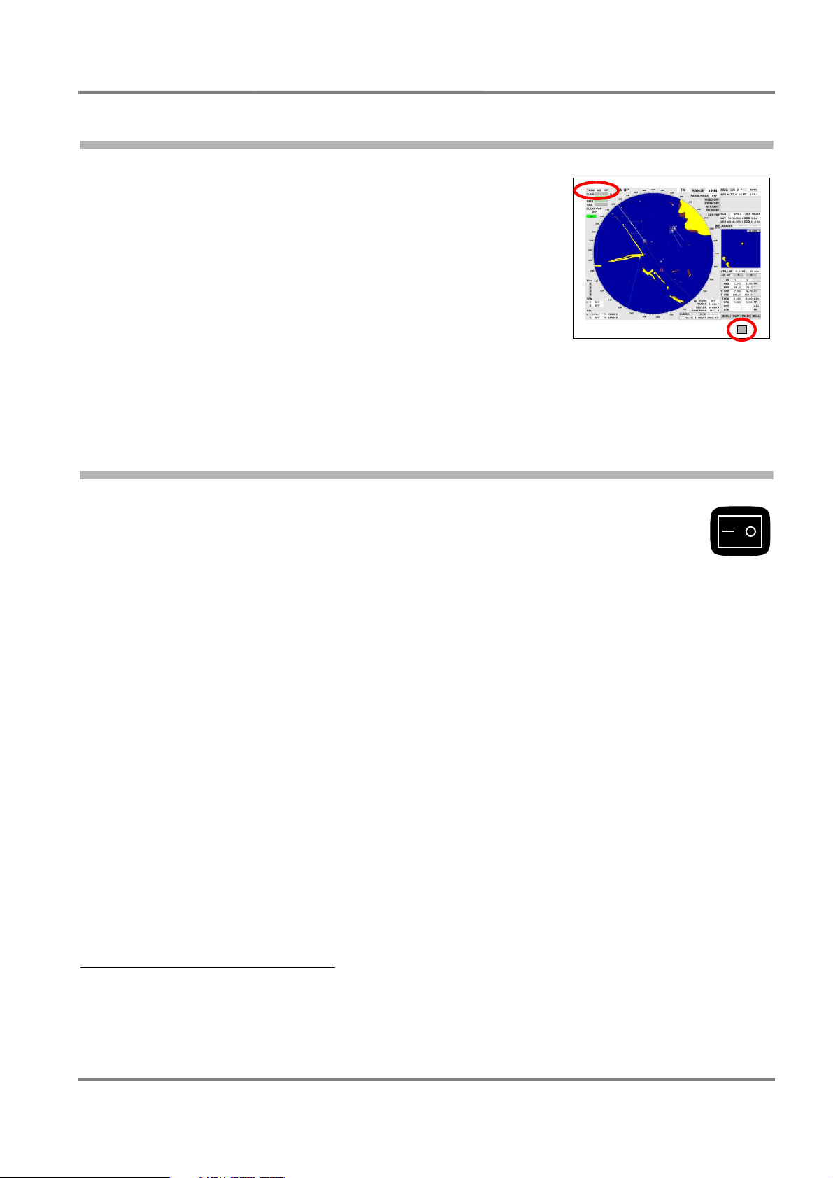
◆ Overview of the screen
◆ The menu structure
2.1 Switching the Radar System On and Off
Switching the radar system ON is done by means of one of the ON/OFF switches or
POWER buttons situated on the radar indicators. When this is done, all indicators and
transceivers are switched on.
1)
and
After the warm-up phase of the magnetron - 3 minutes for X-Band and 3.5 minutes for S-Band - standby operation is achieved and the radar function can be switched on; see page 47.
☞ The act of switching an indicator on never causes a transceiver to be switched directly into radar
Mode.
☞ If an attempt to switch over to radar operation occurs before stand-by operation is achieved, the indi-
cation WARM UP appears instead of the list of transceivers.
Switching the radar system OFF: Switch off all indicators by means of the ON/OFF switch
as there is one of the switches in the ON state, all electronics units of the indicators and transceivers
remain switched on and.
Stand-By Operation
The main difference between stand-by operation and radar operation is that, during stand-by operation,
the transceiver is not transmitting and the antenna is not rotating. Therefore, the radar video is absent on
the PPI, and none of the functions that depend on the transceiver can be operated yet.
2)
. As long
During stand-by operation, the magnetron is kept at its operational temperature.
1)
If an display electronics unit is exposed to very low temperatures (around -15°C or less), it can happen that its computer does not start up.
The screen of the associated monitor then remains dark, or becomes dark after a short time. In this case, the radar system must remain
switched on for about 30 minutes (in spite of the dark screen) so that the display electronics units will warm up. If the radar system is then
switched off and is switched on again after a waiting time of a few seconds, the computer will start up in the normal way.
2)
If a indicator has a POWER key, that indicator is switched off by prolonged pressing of this key.
ED 3038 G 232 / 01 (2002-06)
b_r1_e12.fm / 21.06.02
15

2 Basic Settings; General Remarks about Operating
2.2 General Remarks about the Operating and Display Elements
RADARPILOT / CHARTRADAR
Operating Instructions
2.2 General Remarks about the Operating and Display Elements
On the indicators of the radar system, many screen display fields also act as switching areas or input
fields which can be operated quickly and intuitively by means of the trackball and cursor.
With these few elements, the entire radar system can be operated from the radar indicator with the aid
of its trackball. In addition, the optional radar keyboard contains function keys and rotary knobs for direct
access to some functions that are needed frequently.
☞ The description of the operating procedure in these Operating Instructions normally refers to the
trackball and cursor. In Section 16, the operating procedure using the optional radar keyboard is
summarised.
Trackball and Cursor
☞ If you are already familiar with graphic man-machine inter-
faces, you might be able to skip this section. Before doing so,
for left-handed
people
MORE key...
for right-handed
people
you should have a look at the picture of the trackball beside
this text.
Every operating step begins with the operator moving the cursor
DO key
by means of the trackball to a particular place on the screen (to a
text item, a numerical value, a symbol on the PPI or any desired
place on the PPI). The next step is always the pressing of one of
the trackball keys. In the following, this brief pressing of the key is
called clicking. What then happens depends on the key used, the
element on which clicking took place, and the operating situation,
and is the subject of these operating instructions.
The cursor has a resting position to which it goes 30 seconds after the last operating process. This
position is situated beside the PPI, below the ACQ TGT area.
If the cursor is situated outside the PPI, it is shaped like a hand or an arrow. Inside the PPI, it is a set of
crosswires.
The trackball has three keys with two different functions:
DO Key
The most important key is the middle (bigger) one. Almost all data areas react to this key, which performs
the functions that are needed the most frequently. In these operating instructions, it is called the "DO
key". In the following, "clicking" always means clicking with the DO key unless stated otherwise.
MORE Keys
The two keys situated above the DO key are called "MORE keys" in these operating instructions. They
have identical functions
1)
which are not needed as frequently. Not all elements which can be operated by
means of the DO key react to the MORE key also, and if they do, then always with functions other than
those of the DO key. Furthermore, by pressing of the MORE key, open menus (for menus, see below)
can generally be closed without any results, and inputs can be aborted.
Data Areas
Some data areas are used only to display numerical values, names or stati.
Example: Target data display
In the case of most data areas, the operating procedure for the functions displayed there is likewise
performed by clicking on the data area.
1)
There are two "MORE" keys so that both left-handed people and right-handed people can operate them ergonomically. Their functions are
identical.
16
ED 3038 G 232 / 01 (2002-06)
b_r1_e12.fm / 21.06.02
RADARPILOT / CHARTRADAR
Operating Instructions
2 Basic Settings; General Remarks about Operating
2.2 General Remarks about the Operating and Display Elements
Examples:
- Two switch Acquisition/Guard Zone 1 on and off, all that you need to do is to click on the AK / GZ1
1)
button
.
- If the transfer of the course is to be synchronised, click on the currently existing heading value. A
numeric keyboard is then displayed. Input the correct value by means of that keyboard.
And so on.
Basically, the following is true:
Coloured data areas indicate the activated state.
In the case of functions which only have an "on" state and an "off" state, the "on" state is indicated by a
coloured background. Example: IR on a grey background means that Interference Rejection is not
switched on; IR on a coloured background means that it is switched on.
Areas that are flashing in colour signify that the corresponding function (e.g. ACQ TGT, ADJUST etc.)
can be executed.
Sensitive and Insensitive Data Areas
Data areas that can be operated can be insensitive in particular operational states, i.e. they cannot be
operated. For example, after clicking on the TUNE area, tuning can be performed on the master indicator,
but not on a unit switched to act as a slave indicator. On the slave indicator, the TUNE area is displayed
as being insensitive.
☞ Insensitive data area can be recognised from their low-contrast lettering or colouring.
Before pressing of the DO or MORE key, sensitive data areas can be recognised from the black
border which indicates the boundary of the sensitive area as soon as the cursor is situated in this
region. Furthermore, the shape of the cursor changes to that of a hand.
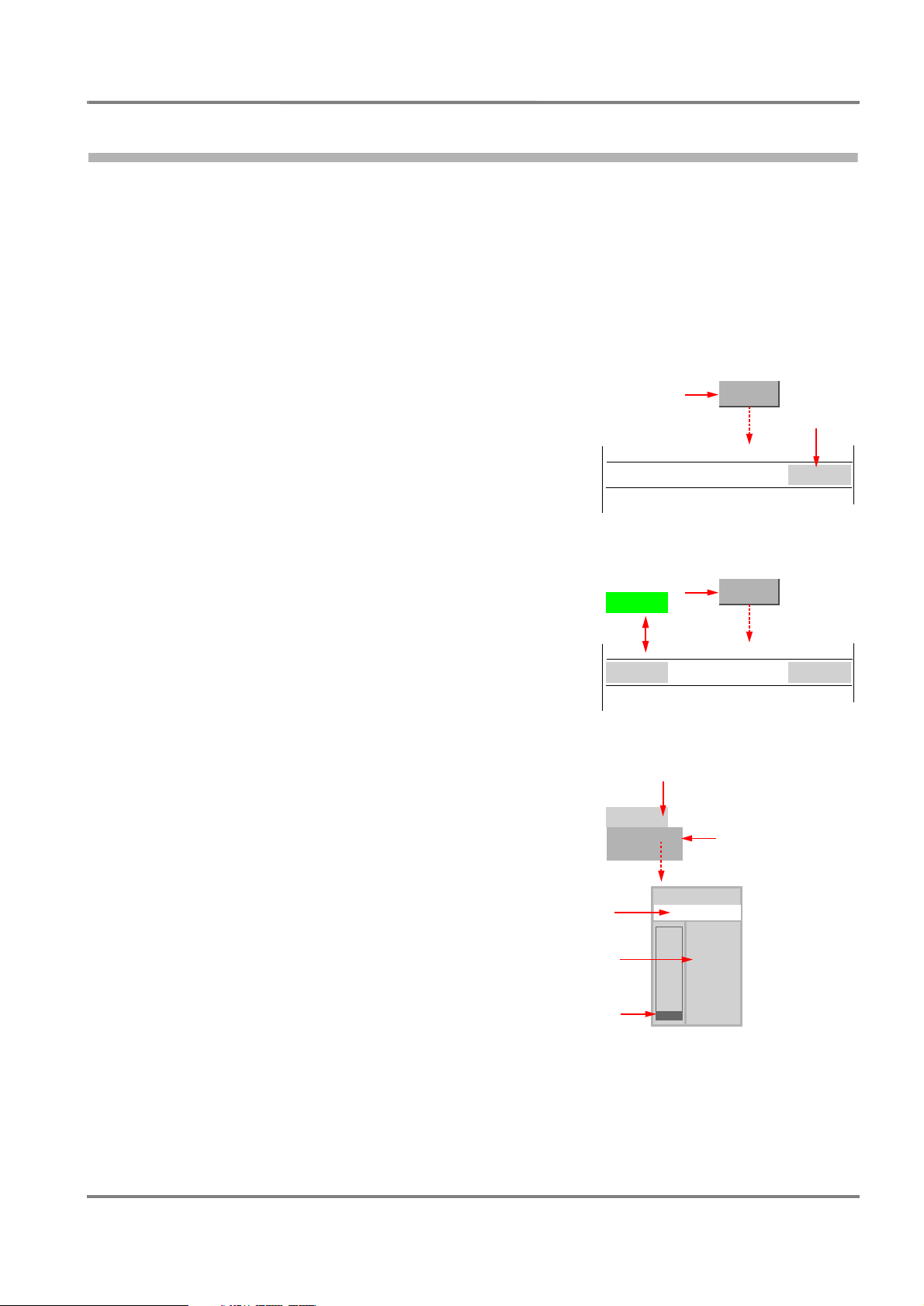
Operating Procedure for the Context Menus
Particular data areas react to clicking by presenting a list of further possibilities - the "context menu", as
it is called. If clicking takes place on one of the buttons contained in the context menu, the corresponding
change in the function takes place and the context menu disappears. In some cases, a further menu is
opened. By clicking on the background area, the context menu can be switched off without any change
of function.
☞ 30 seconds after the last operating process, the context menu switches off automatically.
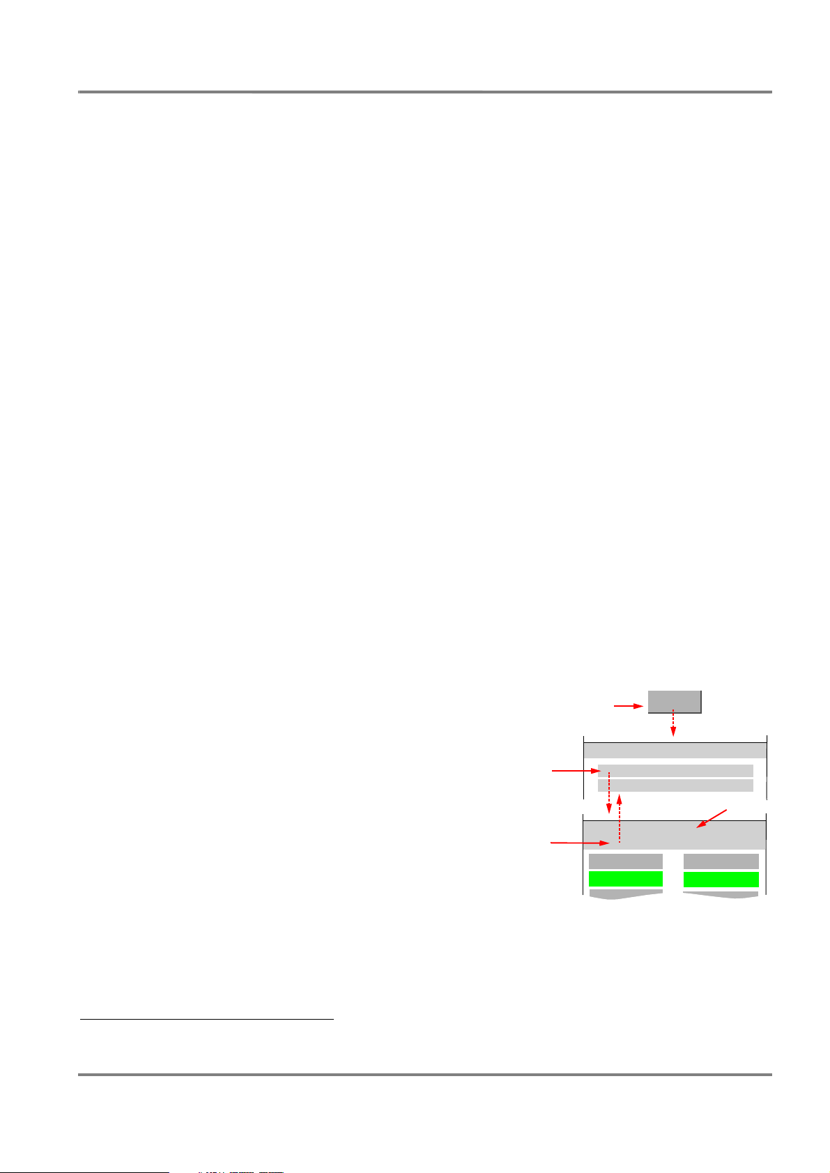
The Function of the Menu Buttons
Clicking on the buttons MENU to BRILL situated at bottom right
opens menus in which basic settings can be made and which
contain other functions that are not needed very often. Most of
these menus contain several levels, i.e. from the menu that has
been called up, a submenu can be called up, and so on. The higher
levels are listed in the menu header. There, you can return to the
higher level by clicking. Clicking on the highest level or on the
menu button having the same name closes the menu.
☞ 30 seconds after the last operating process on the menu, it
switches itself off automatically.
☞ The complete structure of the menu system is shown in
Section 2.7.
2.DO
back: DO
1.DO
MENU
MENU
USER SETTINGS...
UTILITIES...
MENU
USER SETTINGS
USER SETTINGS
BUZZER
HELP
DGPS ONLY
off: DO
DOCKI NG
ZOOM
DEPTH
1)
Data areas which produce an effect as a result of clicking are also called buttons in the following.
ED 3038 G 232 / 01 (2002-06)
b_r1_e12.fm / 21.06.02
17
2 Basic Settings; General Remarks about Operating
2.2 General Remarks about the Operating and Display Elements
RADARPILOT / CHARTRADAR
Operating Instructions
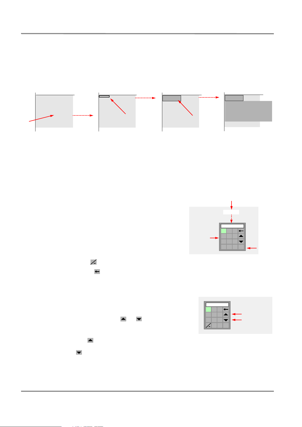
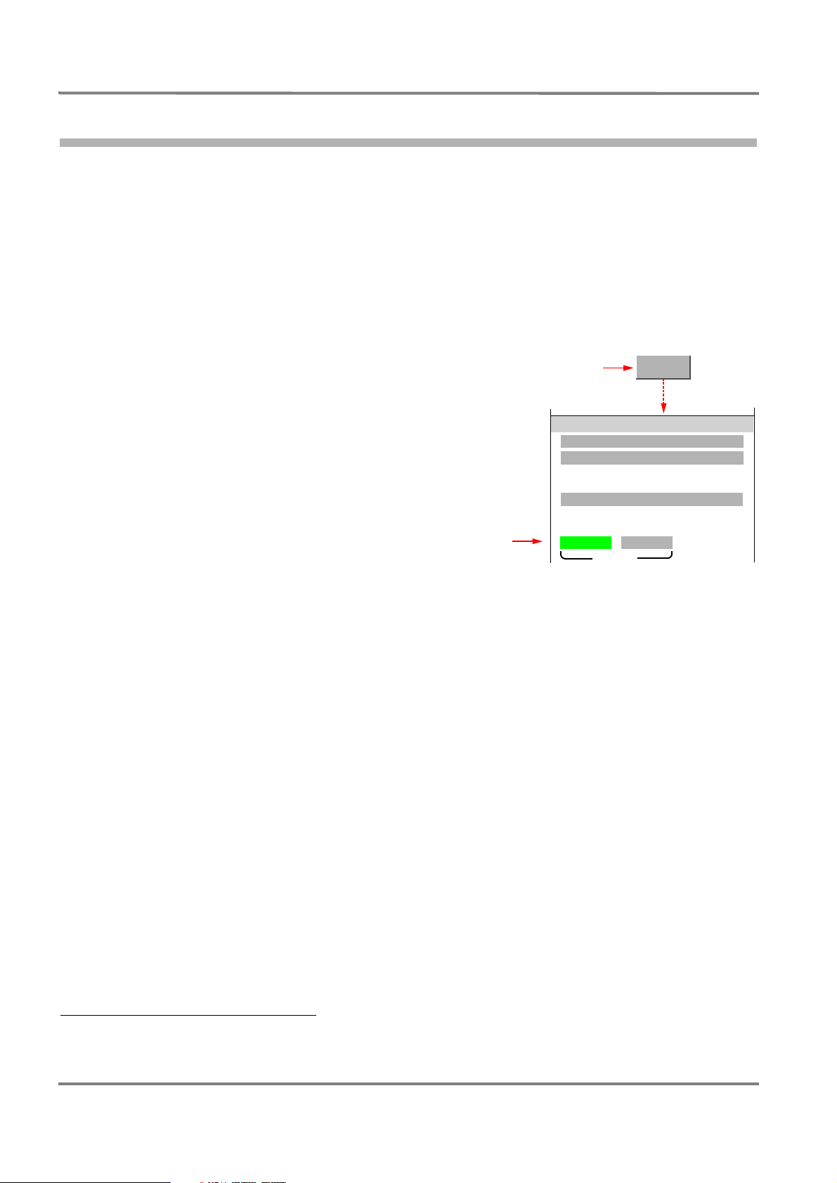
The hidden OTHER button
To switch over the content of entire areas of the screen, e.g. the area containing the Multidisplay or the
radar target data, the OTHER button is used; this button is not continuously visible.
The OTHER button appears in miniaturised form in the top left-hand corner of the display as soon as the
cursor is situated in the relevant display. It appears in normal form as soon as the cursor is situated in
the area of the normal display of the OTHER button. By clicking of this button, a context menu with the
possible display-settings opens up.
OTHER
ZOOM
NEW
TRIAL MANOEUVRE
BUOY, LATER
TRACK SYSTEM
STARBOARD
EDIT MAP
Area to be
switched over
OTHER
DO
Input of Numerical Values
In some areas, numerical values can be entered. This is done with the aid of a virtual keyboard which
appears on the screen as soon as clicking is performed on an area of this kind. With the MORE key, the
input can be aborted without any change occurring.
It is possible to choose between the input of a new value and the changing of the existing value. An
exception to this rule is the input of geographical coordinates, for which different algorithms are applicable.
Entering of a New Value
1. Click on the numerical area; a virtual input-keyboard is
1.DO
HDG 087. 5
opened.
2. Click numerals one after another. They appear in the display
area of the keyboard.
☞ Before the decimal places, click on the point button,
unless the point is entered automatically.
Input
2.DO
1 2 3
4 5 6
7 8 9
0 .
087.5
OK
Take-over:
3.DO
☞ Signs, e.g. for the time zone, can be entered by means
of the button .
+
☞ With the button , the character situated on the right in the display area can be deleted.
3. By clicking on the OK button, the value displayed is taken over and the keyboard disappears.
Changing of an Existing Value
1. Click on the numerical area; a virtual input-keyboard is
opened.
2. With the first pressing of the or button, the value
which exists at that time appears in the display area of the
keyboard.
As long as the button of the virtual keyboard is kept
pressed (with the DO key), the existing value increases. As
long as the button is kept pressed, it decreases.
3. By means of the OK button, the keyboard is made to disappear and the value entered is taken over.
18
1 2 3
4 5 6
7 8 9
+
0 .
DO
DO
OK
ED 3038 G 232 / 01 (2002-06)
b_r1_e12.fm / 21.06.02
Increasing
Decreasing
the value

RADARPILOT / CHARTRADAR
Operating Instructions
2 Basic Settings; General Remarks about Operating
2.2 General Remarks about the Operating and Display Elements
Input of Geographical Coordinates
1. Click on the numerical area; a virtual input-keyboard is
opened.
Here, the existing value appears on the display area of the
keyboard. Instead of the and buttons, the keyboard
008: 36. 437 W
1 2 3
4 5 6
7 8 9
0 .
:
E
W
OK
has the buttons needed for the input of the relevant hemisphere.
2. By the input of numerals, the existing value is overwritten, beginning at the most significant figure.
3. With the "point" button, you go from the "degrees" part to the "minutes" part, from there to the "thousandths of a minute" part, and from there to the W/E, N/S input part.
4. By clicking on the OK button, the value displayed is taken over and the keyboard disappears.
Input of Texts
In some fields, a text line consisting of large and small
letters, numerals and punctuation marks can be entered.
The process corresponds to new input of numbers - see
Caps
Shif t
a s
z x
n m ,c v b
DO
above.
9 0 –6 7 83 4 5‘ 1 2 =
o p [y u ie r tTab q w ]
l ; ’h j kd f g
. /
\
OK
Space
The virtual keyboard which appears after the clicking of
these fields is similar to the usual (English) computer
keyboard:
- By means of the Caps button, a switch-over between
large and small letters takes place.
- By means of the Shift button, all characters are
DO
switched over.
- By means of the button, the character situated on
the right in the display field is deleted.
- The input is completed by clicking on the OK button.
Help Function
As soon as the cursor is situated on an area that can be operated,
the function of the DO key and (if applicable) the function of the
MORE key are displayed in the Quick Info Box at the bottom of the
picture if the Help function is switched on.
Switching the Help Function On and Off
Click on the MENU button, and then, in the USER SETTINGS
menu, click the HELP button.
Caps
Shif t
2.DO
3.DO
A S
Z X
( ) _^ & *# $ %~ ! @ +
O P {Y U IE R TTab Q W }
L : "H J KD F G
N M <C V B
1.DO
> ?
MENU
MENU
USER SETTINGS
HELP
|
OK
Space
ED 3038 G 232 / 01 (2002-06)
b_r1_e12.fm / 21.06.02
19
2 Basic Settings; General Remarks about Operating
2.2 General Remarks about the Operating and Display Elements
RADARPILOT / CHARTRADAR
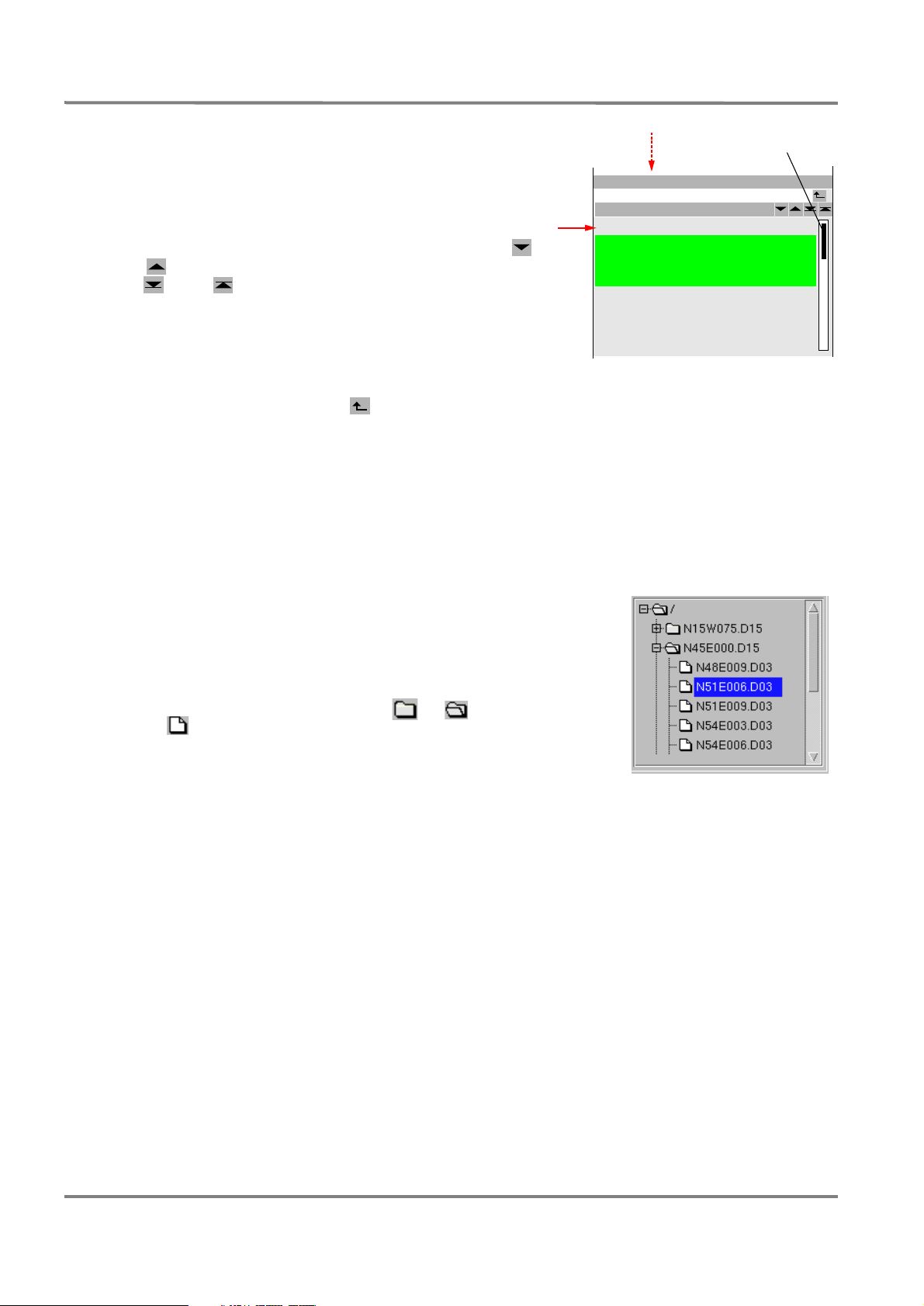
Operating Instructions
Operating Procedure for the Lists
Scroll bar
Lists are used for selection and display of the elements
contained in them. Marking of a list element is done by
clicking.
If the list contains more entries than can be simultaneously
displayed, it can be scrolled line-by-line by means of the
and buttons and from page to page by means of
the and buttons, or by clicking below or above the
scroll bar. Alternatively, click on the scroll bar and scroll by
means of the trackball.
Lists often indicate the files which are contained in a catalog.
4a.DO
/ATLANTIC
No.
1301
1302
1303
1304
1305
1306
1307
1308
Load Track(s)
Name
HELSI NKI- BRIXAM
BRIXAM-MIAMI 1
BRIXAM-MIAMI 3
BRIXAM- FREEPORT
BRIXAM-MIAMI 2
BRIXAM-MIAMI 5
FREEPORT-MIAMI
FREEPORT-MIAMI 1
For example, the list shown here indicates the files of tracks
which are contained in the catalog ATLANTIC. Other catalogs
too can exist. By clicking on the button, the higher level
is displayed, i.e. in this example the list of the catalogs.
☞ Many lists also have a search function: If you click into the input field (at the top of the list), the
virtual keyboard which then opens up enables you to enter the number or the beginning of the name
of the list entry that is being searched for. If you click on ENTER, the list jumps to the entry that is
being searched for.
Special Features of the Lists of the System Maintenance Manager
The System Maintenance Manager, a subroutine which was created
for maintenance purposes and which the operator too needs from
time to time (see page 133), uses a different form of list which is
similar to that of other operating systems. Important special features
are:
Catalogs and files of the various levels are contained in one and the
same display.
Catalogs are designated by the symbol or , and files by the
symbol .
A minus sign in the square in front of the catalog symbol shows that
the catalog content is displayed. Clicking on a square with a plus
sign causes display of the catalog content.
☞ At the top of the list, the character "/" stands for the root (the
basic list). Marking of this entry selects the sum of all catalogs
and files that are present in the list.
20
ED 3038 G 232 / 01 (2002-06)
b_r1_e12.fm / 21.06.02

RADARPILOT / CHARTRADAR
Operating Instructions
2.3 Brilliance and Colour Selection
2 Basic Settings; General Remarks about Operating
2.3 Brilliance and Colour Selection
For the approximate but usually adequate adaptation of the
screen brilliance to suit the brightness of the surroundings,
1.DO
BRILL
there is a choice between 6 colour palettes.
Fine adjustment of the overall brilliance and of the contrast is
possible. Furthermore, the brilliance of the PPI element groups
BRILLIANCE
can be adjusted individually.
MANAUTO
NIGHT
Selecting the Brilliance and the Colour Palette
Click on the BRILL button.
- By clicking on the DAY button, the medium daytime
1)
colour palette NORMAL DAY is switched on.
- By clicking on the NIGHT button, the medium night-time
colour palette NORMAL NIGHT is switched on.
2.DO
DEGAUSS
DAY
BRIGHTNESS
CONTRAST
PANEL
SETTINGS...
- To switch on the other daylight colour palettes, click on
the DAY button with the MORE key and select the
desired palette.
- To switch on the other night-time colour palettes, click on the NIGHT button with the MORE key and
select the palette.
Displaying Areas of the Electronic Chart in Grey Shades (on the CHARTRADAR only)
☞ On the CHARTRADAR, the BRILLIANCE menu in Chart
Display Mode additionally contains the GREY MODE
button. If this function is switched on, the areas of the Electronic Chart are displayed not in colour but in grey shades.
In this type of display, the coloured radar video and
symbols are visually easier to distinguish from the background.
DO
GREY MODE
BRILLIANCE
DEGAUSS
MANAUTO
How to Brighten a Very Dark Screen
If the screen is set very dark in a very bright environment, it might no longer be possible to recognise
anything on the screen. Thus, the brilliance can no longer be increased in the manner described. A way
out of this "trap" is offered by a brilliance increase by means of the DO and MORE keys:
Press the DO key and a MORE key; with the second MORE key, make the screen brighter step by step.
Fine Adjustment of the Monitor Brightness and Contrast
These adjustments are performed by means of the brightness and contrast knobs of the monitor. On
monitors which do not have these operating elements, the adjustments are performed as follows
1. Click on the BRILL button.
1.DO
BRILL
2. Click on the BRIGHTNESS area or on the CONTRAST
area.
3. Perform the desired adjustment with the trackball.
CONTRAST
4. Press the DO key.
1)
All colour information in these operating instructions refers to the average colour palette for daytime, namely NORMAL DAY.
2)
Monitors are also used, which only have a brightness control and no contrast control.
2.DO
90%
2)
4.DO
:
3.
ED 3038 G 232 / 01 (2002-06)
b_r1_e12.fm / 21.06.02
21

2 Basic Settings; General Remarks about Operating
2.3 Brilliance and Colour Selection
RADARPILOT / CHARTRADAR
Operating Instructions
Setting the Brilliance of Individual Elements
1. Click on the BRILL button.
2. Click on the SETTINGS button.
3. Now, by means of the procedures already described, the
following items can be set:
- After clicking on the LAMPS area: the brilliance of the
lamps on the keyboard.
- After clicking on the DATA area: the brilliance of the
whole area outside the PPI.
- After clicking on the SCALE area: the brilliance of the
compass scale.
- After clicking on the VIDEO area: the brilliance of the
radar video.
- After clicking on the SYMBOLS area: the brilliance of
the target synthetics and of the own ship symbol.
- After clicking on the MARKER area: the brilliance of
the cursor, heading line, stern line, EBL’s, VRM’s and
range rings.
- After clicking on the MAP (or MAP / CHART) area: the
brilliance of the map (or chart), tracks and guard
zones.
These settings can independently be made for each colour
palette.
1.DO
2.DO
SETTINGS
3.DO
LAMPS
DATA
SCALE
VIDEO
SYMBOLS
MARKER
MAP
In Chart Display Mode, this area is
labelled MAP / CHART
BRILL
Setting the Optional Illumination of the Optional Keyboard
Setting is performed in the BRILLIANCE menu by means of the
PANEL area. During this process, the procedure already
described should be used.
PANEL
1.DO
BRILL
2.DO
3.
90%
4.DO
22
ED 3038 G 232 / 01 (2002-06)
b_r1_e12.fm / 21.06.02
RADARPILOT / CHARTRADAR
Operating Instructions
2 Basic Settings; General Remarks about Operating
2.4 Degaussing
This section is relevant only for monitors with cathode ray tubes, and not for monitors with flat screens.
As a result of changes in the magnetic field at the location of the monitor, the shadow mask of the
cathode ray tube might become magnetised, which leads to discolouration over the entire screen or in
parts of the display. Because, in the earth’s magnetic field, the ship itself acts as a magnet, such changes
in the magnetic field can also be caused by changes in the ship’s course. The demagnetisation which
then has to be performed on the shadow mask ("degaussing") can be performed manually.
☞ If this does not lead to success, the trouble might also be due to magnetic components or magnet-
ised housings, which must then be removed from the environment of the monitor or degaussed.
2.4 Degaussing
Manual Degaussing
Manual degaussing is performed by pressing of the
DEGAUSS key on the monitor. On monitors which do not
have this key, a corresponding button is active:
Click on the BRILL button and then on the DEGAUSS MAN
area.
Automatic Degaussing
With particular types of monitor, it also possible to set automatic degaussing. When the autodegauss function is switched
on, degaussing takes place at adjustable intervals of time, and
also when the course has been changed by a predefined
amount after the last degauss.
Switching the Autodegauss Function On and Off
Click on the BRILL button and then on the AUTO DEGAUSS
area.
Setting the Autodegauss Function
1. Click on the BRILL button, and then click on the AUTO
DEGAUSS button by means of MORE.
2. Click on the TIME area by means of the MORE key; then,
in the menu that is opened as a result, either
a) click on the desired time interval, or
b) click into the (vertical) bar-area, drag the bar to the
desired value, and press the DO key, or
c) click into the upper numerical area and enter the
value by means of the virtual keyboard.
3. Click on the TURNING field by means of the MORE key;
then, in the same way, input the course change for which
automatic degaussing is to take place.
AUTO
DO
AUTO
1.MORE
AUTO
TIME
TURNING
DO
2.c
DO
2.a
DO
2.b
1.DO
DEGAUSS
1.DO
DEGAUSS
DEGAUSS
2. DO
AUTO TIME
10 min
180 min
120 min
60 min
30 min
20 min
10 min
OFF
BRILL
2.DO
MAN
BRILL
MAN
ED 3038 G 232 / 01 (2002-06)
b_r1_e12.fm / 21.06.02
23
2 Basic Settings; General Remarks about Operating
2.5 Display Modes
RADARPILOT / CHARTRADAR
Operating Instructions
2.5 Display Modes
If there is a CHARTPILOT connected, two Display Modes are available on the RADARPILOT:
- Radar Display Mode: PPI with all radar and ARPA or EPA functions. The map edited on the radar
as per Section 12 can be displayed - see Section 3.12.
- Chart Display Mode: PPI with all radar and ARPA or EPA functions. Instead of the map, the User
Chart Objects that exist in the CHARTPILOT can be displayed - see Section 3.10.
On the CHARTRADAR, the Chart Display Mode has a significantly extended functionality: in addition to
the User Chart Objects, the vector charts that are present on the CHARTPILOT can be displayed also see Section 3.11.
1)
Switch-Over of the Display Modes
Switch-over is performed by means of the keys RADAR and
CHART . The lamp above the keys indicates the Display Mode
that is currently switched on.
Alternatively, switch-over can be performed by means of
buttons: on the display, click on the MENU button, and then
click on the desired mode button.
☞ When Radar Display Mode is switched on, the button
beside the MENU button is called MAP; when Chart
Display Mode is switched on, the name changes to
CHART.
2.DO
1.DO
MENU
MENU
USER SETTINGS.. .
UTILITIES...
MAINTENANCE
CHARTRADAR
MODE
1)
In the case of a CHARTRADAR configured as per IEC 60936-3 (see footnote on page 9), while Head-Up Mode is switched on, the display
of the chart is not permissible. While Head-Up Mode is switched on, it is not possible to switch over to Chart Display Mode.
24
ED 3038 G 232 / 01 (2002-06)
b_r1_e12.fm / 21.06.02
RADARPILOT / CHARTRADAR
Operating Instructions
2 Basic Settings; General Remarks about Operating
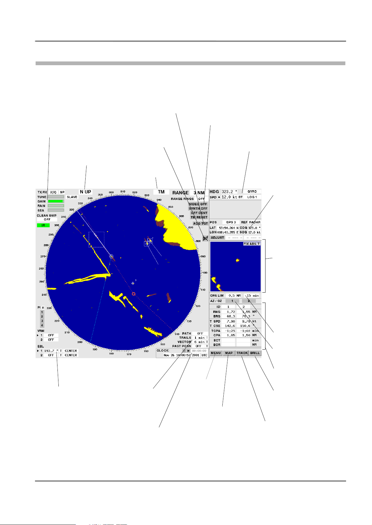
2.6 An Overview of the Screen
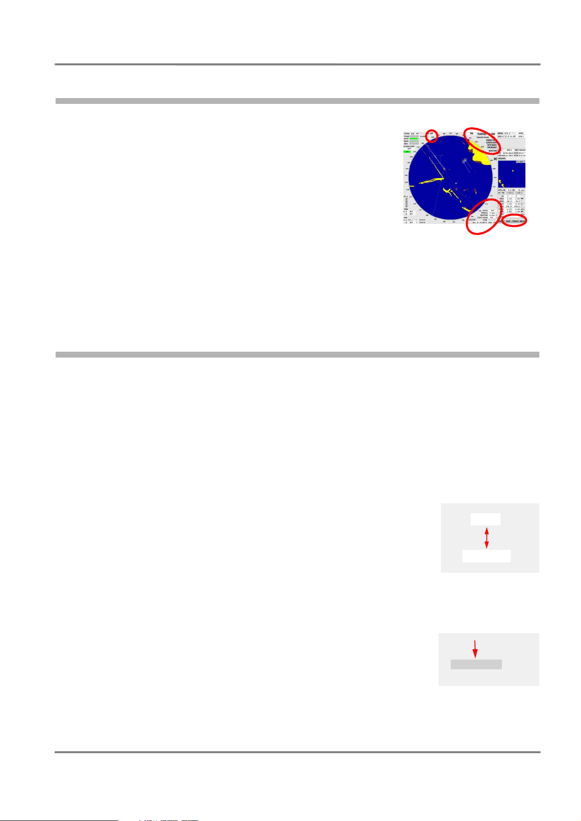
2.6 An Overview of the Screen
The following illustration provides an overview of the arrangement of display elements and operating
elements on the screen in the Radar Display Mode and in the Chart Display Mode.
Transceiver settings:
stand-by/radar operation (p. 47)
master/slave (p. 48)
transceiver selection (p. 48)
radar video setting (p. 49)
antenna revolution rate (p. 52)
PPI orientation (p. 30)
Acquiring targets (p. 69)
deleting targets (p. 70)
Alarm symbol for calling
up the existing warnings
(p. 118)
PPI movement (p. 29)
Radar PPI:
range selection (p. 31)
centering/off-centering (p. 31)
suppression of synthetics/radar video (p. 53)
Compass course (p. 57)
speed (p. 58)
Position display:
data of position sensor (p. 60):
system position, course and
speed over ground
or
cursor position (p. 63),
Multidisplay:
Selectable display of:
alarm list (p. 119),
navigation sensor data (p. 58,
61),
trial manoeuvre (p. 79),
Zoom Display (p. 100),
Depth Display (p. 103),
Wind/Set+Drift display (p. 103),
Docking Display (p. 99),
EDIT TRACK menu (p. 85),
EDIT MAP menu (p. 93),
track lists/catalogs (p. 37)
Measurement aids:
Parallel Index Lines (p. 66)
VRM (p. 63)
EBL (p. 64)
ED 3038 G 232 / 01 (2002-06)
b_r1_e12.fm / 21.06.02
Setting of
path prediction (p. 35)
trails (p. 36)
vectors (p. 34)
past plots (p. 34)
Quick Info Box (p. 105)
with further information:
ETA to cursor position
date, time, stop watch,
help function
Menus for further
functions (p. 26)
Setting display
- of the map (p. 45)
- of the chart (p. 42)
- of the User Chart Objects
(p. 41 or 42)
editing maps (p. 93)
Alarm limit values of collision avoidance (p. 77)
Switching on/off the acquisition/guard zone (p. 69)
Radar target data (p. 70)
system track data (p. 39)
Brightness setting (p. 21),
degaussing (p. 23)
Setting
- display of the tracks (p. 37)
- system track (p. 39)
- next waypoint (p. 40)
editing tracks (p. 85)
25
2 Basic Settings; General Remarks about Operating
2.7 The Menu Structure
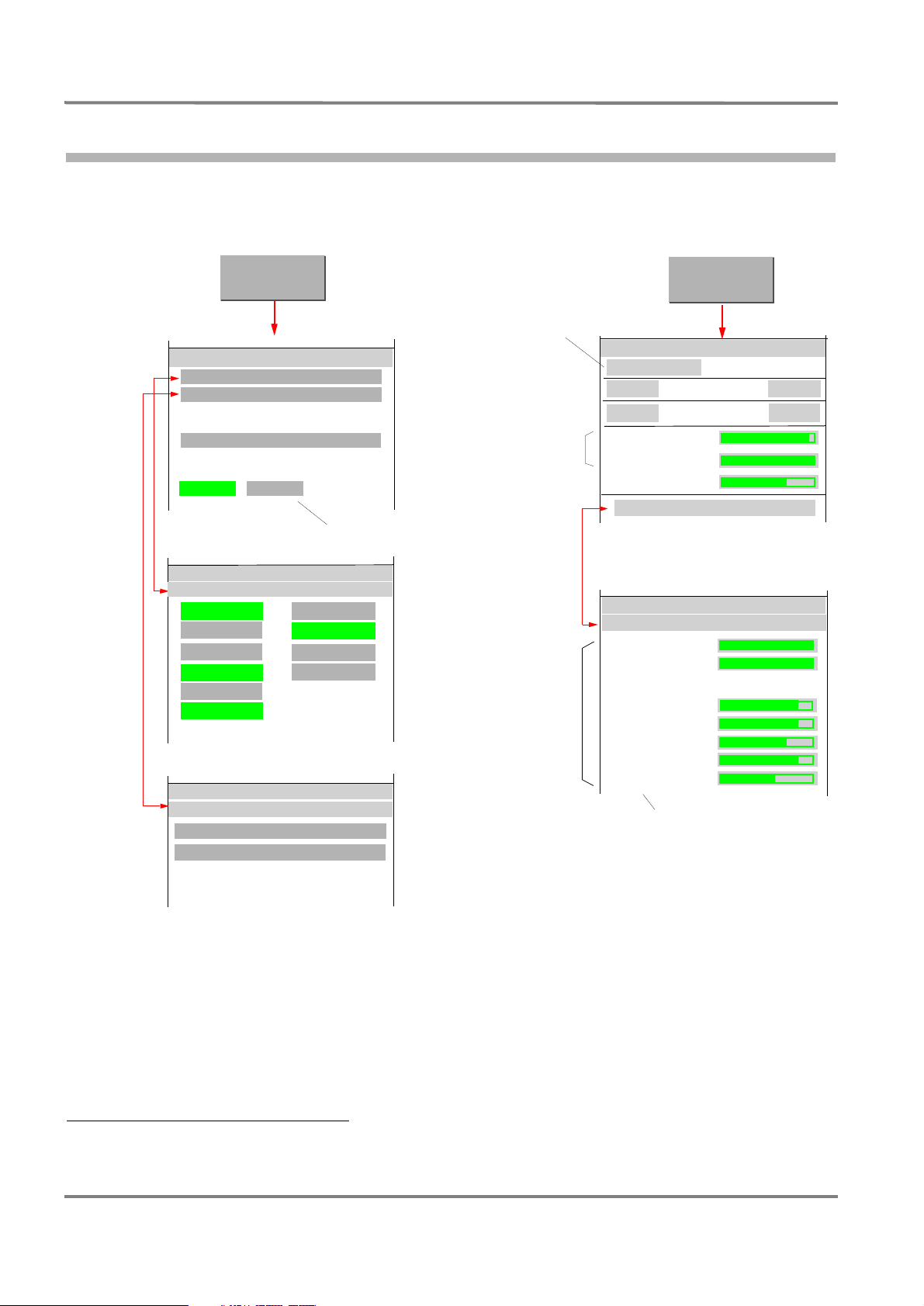
2.7 The Menu Structure
RADARPILOT / CHARTRADAR
Operating Instructions
The following diagram shows the structure of the menu systems which can be accessed via the button
1)
situated at bottom right.
MENU
BRILL
Page 21, (only on the
Page 133
Page 24
MENU
USER SETTINGS...
UTILITIES...
MAINTENANCE
CHARTRADAR
CHARTRADAR)
Present only if there is a
Page 23
Page 21
Page 21
Page 22
GREY MODE
DAY
BRIGHTNESS
CONTRAST
PANEL
BRILLIANCE
DEGAUSS
SETTINGS.. .
CHARTPILOT installed
MENU
USER SETTINGS
Page 117
Page 19
Page 60
Page 34
Page 35
Page 72
Page 79
Page 131
BUZZER
HELP
DGPS ONLY
OS SYMBOL
STERN
TGT LABEL
UTILITIES
TRIAL MANOEUVRE
PERFORMANCE MONITOR
DOCKING
ZOOM
DEPTH
WI ND
MENU
Page 99
Page 100
Page 103
Page 102
Page 22
LAMPS
DATA
SCALE
VIDEO
SYMBOLS
MARKER
MAP
In Chart Display Mode, this area
is labelled MAP / CHART
BRILL IANCE
SETTI NGS
MANAUTO
NIGHT
1)
Because of the individual system configuration, menus might differ from these diagrams. In the descriptions, this is pointed out in individual
cases.
26
ED 3038 G 232 / 01 (2002-06)
b_r1_e12.fm / 21.06.02

RADARPILOT / CHARTRADAR
Operating Instructions
2 Basic Settings; General Remarks about Operating
2.7 The Menu Structure
Page 45
Page 93
Page 41
In Radar Display Mode
(on the RADARPILOT and
on the CHARTRADAR)
MAP
MAP
MAP
EDIT MAP...
SYMBOLS
VISIBLE
SIMPLIFIED
Present only if there is a
CHARTPILOT installed
When the Display Modes
are switched over, the
button changes its name
Page 41
Page 41
Page 41
Page 41
Page 41
In Chart Display Mode
on the RADARPILOT
CHART
CHART
USER CHART OBJECTS
VIDEO ON TOP
AREAS FILLED
SYMBOLS
TEXT LABELS
In Chart Display Mode
on the CHARTRADAR
SIMPLI FIED
Page 37
Page 38
Page 39
Page 40
Page 38
TRACK
TRACK
VISI BILITY.. .
TRACKS
LOAD...
CLEAR.. .
SYSTEM TRACK
SET...
SELECT NEXT WPT...
TRACK
VISIBILI TY
COURSE
LEG
WPT NUMBER
WPT SYMBOL
EDIT...
DELETE...
CANCEL
Page 85
Page 91
Page 40
Page 42
Page 43
Page 44
Page 43
Page 44
Page 44
Page 45
Page 44
CHART
CHART
CHART
USER CHART OBJECTS
VIDEO ON TOP
AREAS FILLED
CATEGORY
SYMBOLS
TEXT LABELS
EDIT MAP...
EDIT MAP...
EDIT MAP...
EDIT MAP...
EDIT MAP...
EDIT MAP...
Standard Land Features
EDIT MAP...
EDIT MAP...
VISIBLE
STANDARD
SIMPLIFIED
VISIBILITY GROUPS...
CHART
VISIBILITY GROUPS
Cautionary Area
Information Areas
Light/Fog Signals
Pilot Signal Stations
Service Stations
Other Land Features
Shallow Soundings
C-MAP
ED 3038 G 232 / 01 (2002-06)
b_r1_e12.fm / 21.06.02
27

2 Basic Settings; General Remarks about Operating
2.8 Activating/Deactivating of Slave Keyboards/Trackballs
RADARPILOT / CHARTRADAR
Operating Instructions
2.8 Activating/Deactivating of Slave Keyboards/Trackballs
When a slave monitor is installed together with a trackball and (possibly) a keyboard, this combination
can perform the same functions as the radar indicator to which these units are connected.
☞ If there are "radar indicators" on the bridge wings, they are often slave monitors and slave
keyboards/trackballs.
If there are one or more slave keyboards or slave trackballs connected to an indicator, only one of them
is active at a time; operating procedures can be performed only on the one that is active.
Activating a Keyboard or Trackball
A non-active keyboard or trackball is activated by pressing the DO key for three seconds.
☞ The keyboard/trackball that had been active up until then is thus deactivated. The associated monitor
acts as a slave monitor.
If there is a keyboard present, activation can also be performed by pressing one of the keys RADAR
MODE, CHART MODE or CONN MODE for three seconds. In this case, when the activation occurs, the
switch-over assigned to the key is also performed, see Section 16.
28
ED 3038 G 232 / 01 (2002-06)
b_r1_e12.fm / 21.06.02
RADARPILOT / CHARTRADAR
Operating Instructions
3.1 Screen Stabilisation of the PPI: True Motion, Relative Motion
3 PPI Settings
Subjects of this Section:
◆ Basic settings of the PPI
- Stabilisation of the radar picture: RM, TM
- PPI orientation: Head-Up, North-Up, Course-Up
- Centering / off-centering of the radar picture
- Selection of range
◆ Setting of the synthetics elements
- Own ship symbol: heading line, speed vector, past position
plot, path prediction
- Target synthetics: speed vectors, past position plots, trails
- Display of the range rings
◆ Setting the display of tracks, defining System Track and next waypoint
◆ Setting the display of the map and the User Chart Objects
◆ Setting the display of the chart on the CHARTRADAR
3 PPI Settings
3.1 Screen Stabilisation of the PPI: True Motion, Relative Motion
As far as the screen stabilisation of the PPI is concerned, there is a choice between the following:
True Motion (TM): The radar video is fixed; the own ship symbol moves across the screen. The PPI
orientation is North-Up or Course-Up. Either manually, or automatically by means of a TM Reset,
the own ship symbol on the PPI is reset in good time before the PPI boundary is reached; this resetting is done in such a way that the larger part of the PPI lies ahead of own ship.
Relative Motion (RM): Own ship’s position is fixed; the radar video moves relative to own ship in accord-
ance with the movement of own ship. As far as the PPI orientation is concerned, it is possible to
choose between Head-Up, North-Up and Course-Up.
Switching Over between TM and RM
Clicking on the PPI stabilisation area causes a switch-over between
TM and RM.
TM
DO
☞ If the PPI orientation setting is Head-Up, then when switch-over
to TM mode takes place there is automatic selection of North-Up
and setting of the display of trails to "true". In TM mode, relative
trails cannot be displayed.
In RM mode, there is also an indication in the PPI stabilisation area stating whether the trails and
vectors are displayed as relative RM (R) or true RM (T).
RM( R)
Manual TM Reset
A TM reset is performed by clicking of the TM RESET area.
☞ The TM RESET area appears, instead of the CENTER area,
only when a switch-over to TM mode is performed.
ED 3038 G 232 / 01 (2002-06)
b_r1_e21.fm / 21.06.02
DO
TM RESET
29

3 PPI Settings
3.2 PPI Orientation: Head-Up, North-Up, Course-Up
RADARPILOT / CHARTRADAR
Operating Instructions
Automatic TM Reset
In good time before an automatic TM Reset takes place, the TM RESET area begins to flash. If the TM
Reset is not then performed manually, it takes place automatically.
3.2 PPI Orientation: Head-Up, North-Up, Course-Up
As far as the PPI orientation is concerned, there is choice between the following:
Head-Up: The heading of own ship points upwards.
☞ Head-Up is available only in RM mode.
North-Up: Geographic North points upwards.
Course-Up: The course which exists at the instant of switch-on or re-orientation of this mode points
upwards.
☞ With every switch-over and re-orientation, the trails are lost; they build up anew in the new mode.
Switching Over between Head-Up and North-Up
When H UP (for "Head-Up") or N UP (for "North-Up") is displayed in
the PPI orientation area, clicking on this area causes a switch-over
between these two modes.
1)
☞ When a switch-over to Head-Up mode takes place, there is an
automatic switch-over to RM mode, and the display of the trails
is set to relative. In Head-Up mode, true trails cannot be
displayed.
N UP
DO
H UP
☞ In Head-Up Mode, the display of the chart is suppressed if the
rate of turn is very large.
Switch-Over to Course-Up Mode
Click into the PPI orientation area by means of the MORE key, and
then click on C UP.
Re-Orientation in Course-Up Mode
When C UP (for "Course-Up") is displayed in the PPI orientation area,
clicking on this area causes the PPI to be rotated and fixed in such a
way that the course which exists at the instant of clicking points
upwards.
Switch-Over from Course-Up to Head-Up or North-Up
Click into the PPI orientation area by means of the MORE key, and
then click on H UP (for "Head-Up") or N UP (for "North-Up").
2.DO
2.DO
H UP
N UP
C UP
H UP
N UP
C UP
1.MORE
H UP
DO
C UP
1.MORE
C UP
1)
In the case of a CHARTRADAR configured as per IEC 60936-3 (see footnote on page 9), while Head-Up Mode is switched on, the display
of the chart is suppressed.
30
ED 3038 G 232 / 01 (2002-06)
b_r1_e21.fm / 21.06.02