

Samcon ExCam IP1354, ExCam IP1357, ExCam IP1364, ExCam IP1365 (MKII), ExCam IP1365 User Manual
ExCam IP13xx
User manual

Doc.-ID: 141021-PT08BA-TG-ExCam IP13xx Series_en_rev.03, page 2 of 44
Content
1 Introduction .............................................................................................................. 5
2 Technical Data .......................................................................................................... 6
2.1 Parameters of the explosion protection ............................................................... 6
2.2 Electrical parameters of the camera .................................................................... 7
2.2.1 Axis P1354 ................................................................................................................................. 7
2.2.2 Axis P1357 ................................................................................................................................. 7
2.2.3 Axis P1364 ................................................................................................................................. 7
2.2.4 Axis P1365 ................................................................................................................................. 7
2.2.5 Axis P1365 MkII ......................................................................................................................... 7
2.3 Electrical parameters of the heating (optional) .................................................... 8
2.4 System cable SKD02-T ....................................................................................... 9
2.5 Supply cable (optional) ...................................................................................... 10
2.6 Technical specification of the camera module ................................................... 11
2.6.1 Axis P1354 ............................................................................................................................... 12
2.6.2 Axis P1357 ............................................................................................................................... 12
2.6.3 Axis P1364 ............................................................................................................................... 12
2.6.4 Axis P1365 ............................................................................................................................... 12
2.6.5 Axis P1365 MkII ....................................................................................................................... 12
2.7 Other technical data .......................................................................................... 13
3 Safety guidelines .................................................................................................... 16
4 Illustration of the model key .................................................................................. 16
5 Commissioning ...................................................................................................... 18
5.1 Step 1: Installation ............................................................................................. 18
5.2 Step 2: Electrical connection ............................................................................. 18
5.2.1 Potential equalization ............................................................................................................... 19
5.2.2 Connection and protection ....................................................................................................... 20
5.2.3 Tests prior to switching on voltage .......................................................................................... 24
5.3 Testing of the status LED .................................................................................. 25
5.4 Step 3: Adjusting the lens .................................................................................. 26
5.4.1 Work preparation ..................................................................................................................... 27
5.4.2 Opening the pressure-resistant housing .................................................................................. 27
5.4.3 Adjusting the focus and angle .................................................................................................. 30
5.4.4 Extracting/inserting an SD storage card .................................................................................. 31
5.4.5 Hardware Reset ....................................................................................................................... 32
5.4.6 Closing of the pressure-resistant housing ............................................................................... 32
6 Network access and visualization ........................................................................ 34
6.1 Browser Support................................................................................................ 34
6.2 Assigning the IP address ................................................................................... 35
6.3 Password / identification .................................................................................... 36
7 Maintenance / Servicing / Alterations ................................................................ ... 37
8 Repairs and Maintenance ...................................................................................... 37
9 Disposal / Recycling .............................................................................................. 37
10 Drawings .............................................................................................................. 38
11 Notes .................................................................................................................... 41

Doc.-ID: 141021-PT08BA-TG-ExCam IP13xx Series_en_rev.03, page 3 of 44
Table of Figures
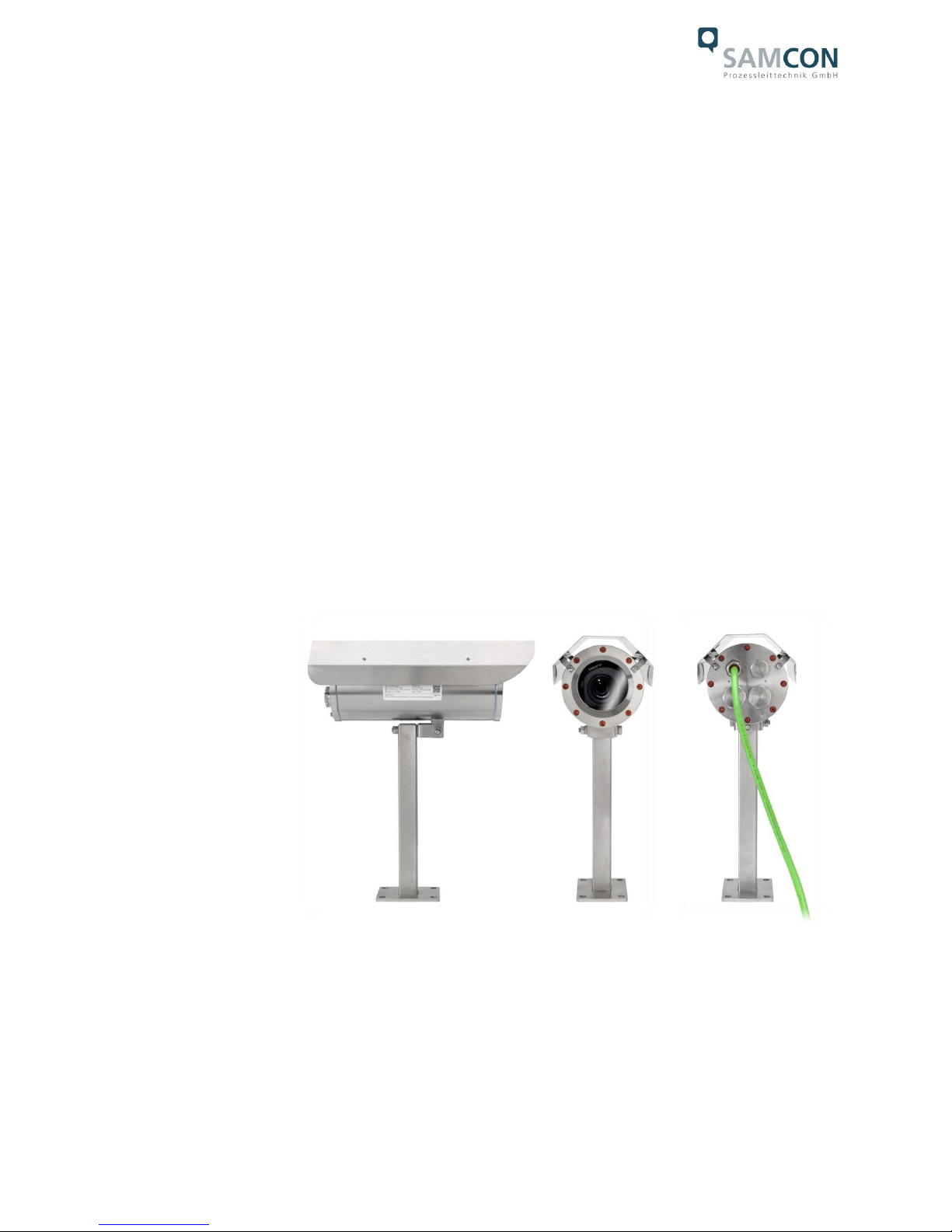
Figure 1.1 – ExCam IP13xx Series with wall mount bracket and roof ............................... 5
Table 4.1 – Model key ..................................................................................................... 16
Figure 5.1 – ExCam IP13xx potential equalization .......................................................... 19
Table 5.1 – Potential equalization .................................................................................... 19
Figure 5.2 – Cable gland and supply cable ..................................................................... 20
Figure 5.3 – ExCam IP13xx T08-VA2.2.K1.BOR-C-XXX-K-N ......................................... 20
Figure 5.4 – ExCam IP13xx T08-VA2.2.K1.BOR-C-XXX-P-N ......................................... 21
Figure 5.5 – ExCam IP13xx T08-VA2.2.K1.BOR-CB-XXX-P(K)-L(L)(H) ......................... 21
Table 5.2 – Pin assignment SKD02-T and plug contact RJ45 ......................................... 23
Figure 5.6 - RJ45 Contact assignment ............................................................................ 23
Figure 5.7 – SKD01 Pin assignment ................................................................................ 23
Tab.5.3 – Pin assignment supply cable ........................................................................... 24
Table 5.4 – Status and control LED ................................................................................. 25
Table 5.5 – Lens data ...................................................................................................... 26
Figure 5.8 – Removing the protection roof (1/2) .............................................................. 28
Figure 5.9 – Removing the protection roof (2/2) .............................................................. 28
Figure 5.10 – Opening the ExCam IPxxx ........................................................................ 29
Abb.5.11 – Mounting adapter with installation components ............................................. 30
Figure 5.12 – Mechanical adjustments at the lens ........................................................... 31
Figure 5.13 – microSD card slot ...................................................................................... 31
Figure 6.1 – Axis IP Utility................................................................................................ 35
Figure 10.1 – Dimensions of the T08 ExCam IP13xx with K1 flange ............................... 38
Figure 10.2 – Dimensions of the T08 ExCam IP13xx with K2 flange ............................... 39
Figure 10.3 – Dimensions of the T08 ExCam IP13xx with accessories ........................... 40

Doc.-ID: 141021-PT08BA-TG-ExCam IP13xx Series_en_rev.03, page 4 of 44
Revision history
Product: T08 ExCam® IP135x Series
Title: User manual ExCam® IP135x Series type 08
Doc. -Id. 141021-PT08BA-TG-ExCam IP135x series_en_rev.01
Author: Thiemo Gruber
Date: October 21, 2014
Rev.- Index
Date
Name
Remarks
Authorization of the EX Supervisor
0
October 21, 2014
T. Gruber
Compilation of the document based on
„140808-PT08BA-TG-ExCam
IP1354_en_rev.02.docx“, Revision of
the title and content / re-naming of the
ExCam IP1354 user manual into
ExCam IP135x Series
Reviewed and approved
October xx, 2014 – S. Seibert
1
December 05, 2014
S.Seibert
Revision and approval
Reviewed and approved
December 05, 2014 – S. Seibert
2
April 13, 2016
T. Gruber
Various revisions: Extension of the
IP13xx Series with Axis products P1364
and P1365 (discontinuation of P1355),
Renaming of the document from IP135x
Series to IP13xx Series. Update of the
document overview chapter 2 (page 7)
3
April 13, 2016
Revisions and corrections for approval
by S. Seibert. Reduction of Axis specific
technical details; stating links to data
sheets and user manuals. Adaptions of
formal details etc. and deletion of the
document overview (chapter 2)
Doc.-ID: 141021-PT08BA-TG-ExCam IP13xx Series_en_rev.03, page 5 of 44
1 Introduction
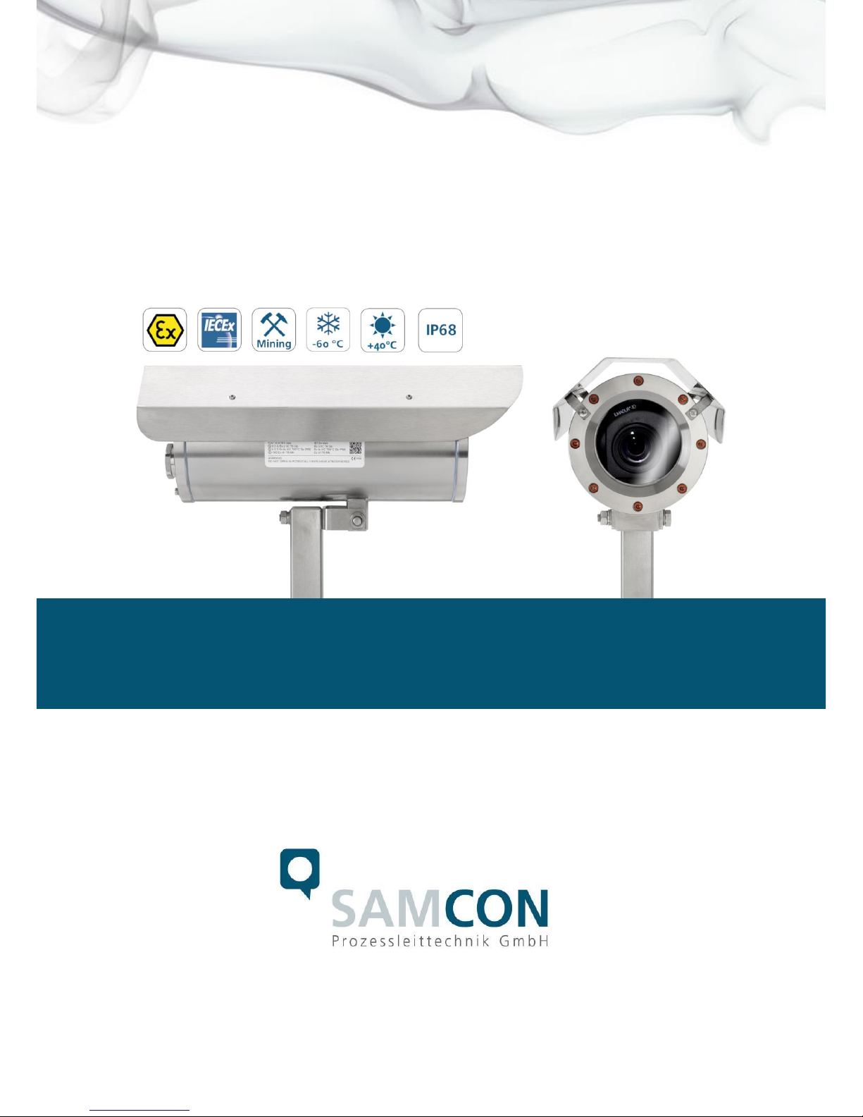
The ExCam IP13xx Series is a camera system (type 08) manufactured by SAMCON
Prozessleittechnik GmbH which can be used for various applications, preferably within
hazardous areas of the chemical and/or petro-chemical industry, at offshore plants, in
mines, and at biogas plants.
The camera Series is suitable for the usage within the Ex zones 1, 2, 21, and 22 including the gas group IIC (all gases, steams, and fogs including acetylene, hydrogen and
carbon disulphide) and the dust group IIIC (conductive dusts and flammable fibrous material), as well as in mining. Besides the stationary use, the explosion-proof cameras of
theT08 ExCam Series are certified to be also used for mobile applications (hand-held
etc.)
The Ex d stainless steel housing allows additional alloys, a powder coating, or coats of
varnishes in different RAL colors as well as various mechanical accessories in order to
extend the resistance towards extreme environmental conditions (salt water, acid, solar
radiation, high mechanical strains etc.). Due to the usage of high-quality PTFE sealings,
not only the protection level IP68 is reached but also the chemical resistance is maximized.
Figure 1.1 – ExCam IP13xx Series with wall mount bracket and roof

Doc.-ID: 141021-PT08BA-TG-ExCam IP13xx Series_en_rev.03, page 6 of 44
2 Technical Data
2.1 Parameters of the explosion protection
Identification marks according to
Directive 94/9/EG (until Apr 20, 2016):
Directive 2014/34/EU: II 2G (zone 1 and 2)
II 2D (zone 21 and 22)
I M2
Explosion protection (gas): Ex d IIC T6 Gb or
Ex d IIC T5 Gb or
Ex d IIB T6 Gb or
Ex d IIB T5
Explosion protection (dust): Ex tb IIIC T80°C Db IP68 or
Ex tb IIIC T95°C Db IP68 or
Ex tb IIIB T80°C Db IP68 or
Ex tb IIIB T95°C Db IP68
Explosion protection (mining): Ex d I Mb
Protection level: IP 68 (IEC /EN 60529)
Transportation / storage temp.(EX): 0° C…+50° C
Ambient temperature (EX)1: -60°C…+65°C (T6)
-60°C…+70°C (T5)
Nominated body: TÜV Rheinland (number 0035)
EC Type Examination: TÜV 14 ATEX 7539 X_1st supplement
IECEx TUR 14.0026X_issue No.1
Additional certificates: EAC-Ex TC_RU_C_DE.MIO62.B.01921
Test protocol ATEX: 557/Ex.539.00/14
Test report IECEx: DE/TUR/ExTR14.0026/00
Quality Assessment Report: DE/BVS/QAR14.0006/00
1
Maximum ambient temperature range relevant for explosion protection might deviate to the maximum functional temperature range.
For maximum functional temperature range (MTBF) see chapter 2.12. Values depending on model

Doc.-ID: 141021-PT08BA-TG-ExCam IP13xx Series_en_rev.03, page 7 of 44
2.2 Electrical parameters of the camera
2.2.1 Axis P1354
Power supply: PoE, IEEE 802.3af class 3
Reference power: ±48 V DC (44...54 V DC)
Maximum power input: 7.2 W
2.2.2 Axis P1357
Power supply: PoE, IEEE 802.3af class 3
Reference power: ±48 V DC (44...54 V DC)
Maximum power input: 7.9 W
2.2.3 Axis P1364
Power supply: PoE, IEEE 802.3af/ 802.3at Type 1 class 3
Reference power: ±48 V DC (44...54 V DC)
Maximum power input: 7.9 W (4.3 W typical)
2.2.4 Axis P1365
Power supply: PoE, IEEE 802.3af/ 802.3at Type 1 class 3
Reference power: ±48 V DC (44...54 V DC)
Maximum power input: 7.9 W (3.6 W typical)
2.2.5 Axis P1365 MkII
Power supply: PoE, IEEE 802.3af/ 802.3at Type 1 class 3
Reference power: ±48 V DC (44...54 V DC)
Maximum power input: 6.8 W (3.6 W typical)

Doc.-ID: 141021-PT08BA-TG-ExCam IP13xx Series_en_rev.03, page 8 of 44
2.3 Electrical parameters of the heating (optional)
Reference power UN: 24 V DC
Nominal power PN: 20 W for type L (T
AMB ≥
-30°)
40 W for type L (T
AMB ≥
-60°)
Attention!
The power consumption of the housing heating is determined by the ambient temperature or, respectively, by the PTC features2 found in the modules’ individual operating
points. In addition, the performance of the PTC load circuit is influenced by the switchingon characteristics of the CB06 circuit board, the load operation of the internal camera
module as well as the convection cooling on the outside (heat dissipation via housing).
Per module, the switch-on power can reach P
max
> 100W! Supply cable fine wire fuses
have to be dimensioned accordingly by the end user. A super-slow (-TT-) trigger characteristic is recommended.
The typical continuous power rating at the low temperature range (T
AMB
-30°C) is
P
(-30°C)
= 12.2 W at a saturated condition
The typical continuous power rating at the artic temperature range (T
AMB
-60°C) is
P
(-60°C)
= 26.8 W at a saturated condition
The typical start-up peak at the low temperature range (1x HP05 heating element) is
I
max
> 4000 mA !
The typical start-up peak at the artic temperature range (2x HP05 heating element) is
I
max
> 8000 mA !
The typical in-rush-duration for I
PTC
< 1000mA per module is tON ≤ 45s
The typical in-rush-duration for I
PTC
< 500mA per module is tON ≤ 120s
(saturated range/ steady current)
2
P
HP05
= KxAxT (K=5.5W/m2)

Doc.-ID: 141021-PT08BA-TG-ExCam IP13xx Series_en_rev.03, page 9 of 44
2.4 System cable SKD02-T
Description: Samcon System Cable Digital (type „SKD02-T“)
for low temperature ranges, data transfer and
power supply of the camera modules M1145
and M1145-L (DIN EN 60079-14: 2014 con-
form)
Sheath color: Yellow-green (GN), similar RAL6018
Ex d marshalling: via the cable gland 13 located on the right
(according to DIN EN 60079-14:2014
[chapter 10.6.2])
At a cable connection length of ≥ 3 m:
(without integrated pressure barrier/ with
elastomer sealing on the outer sheath) e.g.:
„ADE 4F MsNi Type5 - M20x1.5 (CAPRI)“,
with additional strain relief;
At a connection cable length of < 3m:
(with integrated pressure barrier / epoxide
compound grouting of the single conductors
and duroplast/elastomer sealing of the outer
sheath) e.g.: „8163/2 PXSS2K - M20x1.5 (R.
Stahl GmbH)“
Outer diameter: 9.1 ± 0.2mm
Wall thickness: 1.0 ± 0.1mm
Bending radius: 10 x outer diameter at installation
5 x outer diameter after installation
Tensile: Max. 140N
Temperature range: -10° C to +50° C (at point of installation)
-60° C to +80° C (fixed installed)
Conductor design: 4 x 2 x AWG22/1 blank, CAT.6a
Isolation: SFS-PE foamed
Core diameter: 1.52 ± 0.02 mm
Color code: IEC 708-1
Pair shielding: Compound aluminum foil
Shielding: Copper braid, multiple wires 0-10 vz, opt. cov-
erage approx. 85%
Outer sheath: PUR FHF
Characteristics: PUR halogen free, flame resistant (EN 60332-
1-2), UV and ozone resistant, high chemical re-
sistance, EMV shielded
(q.v. www.samcon.eu, data sheet SKD02-T)
3
According to the current standard DIN EN 60079-14:2014, the dimensioning/execution of the cable gland with or without integrated
pressure barrier / compound grouting does not depend anymore on the marked gas explosion group (IIB, IIC) or the Ex d pressure
chamber volume (<2000cm3, ≥2000cm3) but solely on the length of the suitable connection cable (<3m, ≥3m)

Doc.-ID: 141021-PT08BA-TG-ExCam IP13xx Series_en_rev.03, page 10 of 44
User interface: P(Plug) version: RJ-45 Stecker (EIA/TIA-
568B), e.g. Weidmüller IE-PS-RJ45-FH-BK,
Phoenix Contact VS-08-RJ45-5-Q/IP20 etc.,
10BASE-T/100BASE-TX PoE
K(terminal block) version: about 12 cm stripped:
8 x single conductors twisted pair (solid conductor A=0.33mm2, ø=0.64 mm approx. 6 mm
stripped), 1 x shield (Cu braid tinned 1.5 mm2,
ferule color code according to DIN 46228)
10BASE-T/ 100BASE-TX PoE
2.5 Supply cable (optional)
Description: Ölflex® 440P4 (U.I. Lapp GmbH), power supply
for the PTC heat load circuit as well as for the
electronical regulation of the CB06 for T08 Ex-
Cam with the model key „L“ and „LL“,
(DIN EN 60079-14: 2014 conform)
Sheath color: Silver grey (GY) matt, similar RAL7001
Ex d marshalling: via cable gland 2
5
located on the left (according
to DIN EN 60079-14:2014 [Chapter 10.6.2])
At a cable connection length of ≥ 3 m:
(without integrated pressure barrier/ with
elastomer sealing on the outer sheath) e.g.:
„ADE 4F MsNi Type5 - M20x1.5 (CAPRI)“,
with additional strain relief;
At a connection cable length of < 3m:
(with integrated pressure barrier / epoxide
compound grouting of the single conductors
and duroplast/elastomer sealing of the outer
sheath) e.g.:
„8163/2 PXSS2K - M20x1.5 (R. Stahl GmbH)“
Outer diameter: 7.5 mm
Outer sheath: Polyurethane mixture TMPU according to EN
50363-10-2 / VDE 0207-363-10-2
Bending radius: 12.5 x outer diameter (occasional movement)
4.0 x outer diameter (fixed installation)
4
Further cables available upon request, e.g. „Ölflex® Petro FD 865 CP“ (high resistance against oil and drilling liquids) or „XPLE
Armoured 3 x 2.5“ (extremely robust, particularly designed for offshore environments)
5
According to the current standard DIN EN 60079-14:2014, the dimensioning/execution of the cable gland with or without integrated
pressure barrier / compound grouting does not depend anymore on the marked gas explosion group (IIB, IIC) or the Ex d pressure
chamber volume (<2000cm3, ≥2000cm3) but solely on the length of the suitable connection cable (<3m, ≥3m)

Doc.-ID: 141021-PT08BA-TG-ExCam IP13xx Series_en_rev.03, page 11 of 44
Conductor design: 3G1.5 (0012838), 3 x 1.5 mm2 (ø=1.4 mm),
Fine wired tinned copper strand according to.
IEC 60228 / VDE 0295, class 5, with protective
earth (GN/YE)
Copper index: 43.0 kg/km
Weight: 96.0 kg/km
Tensile strength: 15 N/mm2
Characteristics: Resistant to oil and drilling fluids according to
IEC 61892-4: supplement D, wear and notching
resistant, halogen free (VDE 0472-815) and
flame-retardant according to IEC 60332-1-2, re-
sistant to hydrolysis and microbes, UV re-
sistant, additional testing requirements accord-
ing to IEC 60811, EN 50396 and EN 50396
(q.v. www.samcon.eu, data sheet Ölflex 440P)
Conductor identification code: Black conductors with white numbers with
GN/YE- protective earth according to DIN EN
50334 / VDE 0293-334
Classification: ETIM 5.0 Class-ID: EC 000104, ETIM 5.0 type:
Control cable
Conductor insulation: Thermal Plastic Elastomer (TPE)
Nominal current U0/U: 300/500 V AC/DC
Test voltage: 3000 V
Temperature range: -40°C to +90°C (occasional movement)
-50°C to +90°C (fixed installation)
User interface: P(Plug) version: n/a / upon request
K(terminal block) version: 3x 1.5 mm2 (3G1.5)
Cu strand with ferules (color code according to
DIN 46228). Sheath about 12 cm stripped and
furnished with bend relief / shrink tubing
2.6 Technical specification of the camera module
Note:
Technical details of the internal CCTV module such as light sensitivity, resolution, frame
rate sensor, shutter times, lens details, streaming functions, supported network protocols,
event trigger, storage options, and picture parameter setting via the web interface are
thoroughly provided in the data sheets of the camera manufacturer and not part of the
T08 ExCam user manual.

Doc.-ID: 141021-PT08BA-TG-ExCam IP13xx Series_en_rev.03, page 12 of 44
2.6.1 Axis P1354
User manual:
http://www.axis.com/files/manuals/um_p1354_1463736_en_1505.pdf
2.6.2 Axis P1357
Data sheet:
http://www.axis.com/files/datasheet/ds_p1357_1471705_en_1505.pdf
User manual:
http://www.axis.com/files/manuals/um_p1357_1465567_en-1506.pdf
2.6.3 Axis P1364
Data sheet:
http://www.axis.com/files/datasheet/ds_p1364_1511096_en_1512.pdf
User manual:
http://www.axis.com/files/manuals/um_p1364_1510439_en_1601.pdf
2.6.4 Axis P1365
Data sheet:
http://www.axis.com/files/datasheet/ds_p1365_60562_en_1503_hi.pdf
User manual:
http://www.axis.com/files/sales/um_p1365_1489706_en_1507.pdf
2.6.5 Axis P1365 MkII
Data sheet:
http://www.axis.com/files/datasheet/ds_p1365mkii_60562_en_1603.pdf
User manual:
http://www.axis.com/files/manuals/um_p1365mkii_1489706_en_1604.pdf

Doc.-ID: 141021-PT08BA-TG-ExCam IP13xx Series_en_rev.03, page 13 of 44
2.7 Other technical data
Permitted ambient
temperature (MTBF)6: -10 °C … +50 °C (Type N / P1365)
-10 °C ….+40 °C (Type N / P13xx)
-30 °C … +40 °C (Type L)
-60 °C … +40 °C (Type LL)
Protection level EN 60529/ IEC 529: IP68
Test conditions (>IP67): 24h/ 3m water column,
pH-neutrality, temperature of the liquid medium:
+5° C ≤ T
Water
≤ +20° C.
An additional mechanical protection against wa-
ter jets is recommended
Housing material7 of the pressure resistant enclosure (DIN EN 60079-1: 2008) according
to DIN EN 10027-2: 2015-07 (making system for steel):
Housing material (standard) MNo.: 1.4404 (X2CrNiMo17-12-2),
AISI 316L / V4A
Housing material (optional) MNo.: 1.4301 (X5CrNi18-10),
AISI 304 / V2A
MNo.: 1.4305 (X8CrNiS18-9),
AISI 303
MNo.: 1.4401 (X5CrNiMo17-12-2),
AISI 316 / V4A
MNo. 1.4571 (X6CrNiMoTi17-12-2),
AISI 316Ti / V4A
6
Functional temperature range concerning the operational temperature range of the installed components according to manufacture
declarations (MTBF – meantime ration duration between failures). For ambient temperature ranges relevant for explosion protection
(ATEX, IECEx) see chapter 2.1 – Explosion protection)
7
The available stainless steel materials dispose of different specific characteristics such as mechanical and chemical resistance. It is
possible to optimize the corrosion behavior in highly acidiferous environments or at offshore applications by selecting the applicable
housing material. An electro-polished or powder-coated surface in various RAL colors (standard: RAL7035) is possible

Doc.-ID: 141021-PT08BA-TG-ExCam IP13xx Series_en_rev.03, page 14 of 44
Protective coating8: Standard color RAL7035 (all RAL colors
and special colors possible!), DURALMIT®
2K-PUR structure, type DSPT (isocyanate
netted, polyester modified acrylate resin, fine
structure (1.6…2.0 [mm] nozzle), surface re-
sistance ≤ 9^11[Ω], layer thickness ≤ 0.2 [mm],
screw connections, flat gaskets and cable
glands are excluded from the coating
Additional metallic/non-metallic materials
of the Ex d housing protection system:
Zinced spring steel MNo.: 1.0330, PTFE with
glass microbeads (GYLON® Style 3504 blue),
silicone-coating (Silcoset 105 incl. CureAgent
28), VMQ (silicone), thermos transfer foil made
of polyester (aceton resistant), cable glands
made of brass, nickle-plated (MsNi)
Sight glass material: Borosilicate glass (Ilmadur 10/ I-420)
(DIN7080:2005-05)
Internal materials: Aluminum die cast, zinced (protection housing
of the camera module), polyamide (PA6.6/
PA2000) and polyoxymethylene (POM) isolators and supporting adapters, T08 aluminum
universal adapter (EN AW-ALSi1MgMn), PTCceramics, PUR and additional thermoplastic
plastics, optical and electronical components
etc.
Attention: The Axis module is equipped with an
ML614R battery which supplies the real time
clock (RTC). These lithium button cells (3.0 V)
dispose of 1.2 dimethoxymethane; ethylenglycoldimethylether (EGDME), CAS-No. 110-71-4
8
The protective coating of the housing underlies the explosion protection! Affected are exclusively the outside metal surfaces. The
gaps preventing the transmission of an ignition / threads as well as the sealings remain unaffected. The modification of the housing
surface meets the requirements acc. to DIN EN 60079-0: 2012 chapter 7 – non-metallic housings and non-metallic housing components (UV resistance, temperature index TI or relative heat index RTI-mechanical acc. to ANSI/UL 746B or heat and cold resistance).
The avoidance of electrostatic charges is reached by the surface resistance ≤ 9^11 Ω (max. 50% relative humidity) and the limitation
of the layer thickness to 0.2mm (IIC)/ 2mm (IIB). Due to the surface coating, the thermal value and the convection cooling change.
The maximum permitted power loss feed into the housing is not affected by it!

Doc.-ID: 141021-PT08BA-TG-ExCam IP13xx Series_en_rev.03, page 15 of 44
Weight (without accessories): 6800 g (with „K1“ cable gland flange)
7500 g (with „K2“ cable gland flange)
Weight of accessories: 900 g (wall mount bracket WMB-L)
800 g (Twin adapter WMB-xTA)
750 g (Hood WPR-VA2.1)
100 g (Hinge attachment SCH-VA2.x)
450 g (clamp attachment CMB-S)
1200 g (Samcon cool.Jacket VA2.2)
Further accessories upon request!
Dimension (wxhxd)9: 113.0 mm x 138.5 mm x 260.2 mm (K1 flange)
113.0 mm x 138.5 mm x 276.0 mm (K2 flange)
Dimension with accessories (BxHxT)10: 135.0mm x 238.0mm x 413.0mm
(with wall mount bracket and hood)
Fitting of the flame proof gap preventing the transmission of ignition (cylinder) (EX) of the
T07-VA2.2.x.x housing:
Flange / body Nominal diameter: 91 mm (plain cylindrical)
Clearance fit: H8 f7 (DIN ISO 286)
Tolerance: (-71…-36) µm … (0…+54) µm
Gap length > 12.5mm (acc. to DIN EN 60079-1)
largest gap length < 0.15mm (DIN EN 60079-1)
Average surface finish: Ra ≈ 2.0 µm
(DIN ISO 468) / Ra ≤ 6.3 µm acc. to DIN EN
60079-1: 2008 [5.2.2]
Cable glands 2 x M20*1.5_12 mm (ISO metrical fine thread
acc. to DIN13-2), quality 6H (medium or fine
acc. to ISO 965-1 / ISO 965-3), supporting/gripping threads ≥ 5 (acc. to requirements of
DIN EN 60079-1: 2008 [5.3]
table 2 „Cylindrical gaps“)
Media resistance: Checked upon request only!
Generally: Resistant to corrosion as well as
chemically high-resistant to a variety of substances used in the industrial environment and
suitable for offshore applications (q.v. the general specifications of stainless steel MNo.:
1.4404, surface finish of the Ex d housing, Gylon flat sealing etc.)
9
Dimension stainless steel housing T07 VA2.2 with pin and without cable gland and external accessories. For additional / detailed
dimensions see chapter 10 – technical drawings
10
Dimension camera housing T07 VA2.2 with wall mount bracket WMB-L and hood WPR-VA2.2 (axially aligned, maximum depth)

Doc.-ID: 141021-PT08BA-TG-ExCam IP13xx Series_en_rev.03, page 16 of 44
3 Safety guidelines
Please observe the safety guidelines indicated in der EX installation manual of the
T08 ExCam Series!
4 Illustration of the model key
The following model options are currently available for the ExCam IP13xx Series:
Model options
Ex product name
1)
Type2)
Housing
combination
3)
Gas expl.
group
4)
Cable length/m
SKD02-T/Ölflex
440P
5)
Cable
termin.6)
Temperature
range7)
ExCam IP1354,
ExCam IP1357,
ExCam IP1364,
ExCam IP1365
(MKII) …
T08-
VA2.2.K1.BOR-
C-
005-
K- N T08-
VA2.2.K1.BOR-
C-
005-
P- N T08-
VA2.2.K2.BOR-
C-
005-
K- N T08-
VA2.2.K2.BOR-
C-
005-
P- N T08-
VA2.2.K1.BOR-
C-
005-
K- L T08-
VA2.2.K1.BOR-
C-
005-
P- L T08-
VA2.2.K1.BOR-
C-
005-
K-
LL
T08-
VA2.2.K1.BOR-
C-
005-
P-
LL
Table 4.1 – Model key
1) ExCam IP135x = Functional camera description of the ExCam IP13xx Series
2) T08 = Production type concerning the certifications of the „T08
ExCam Series“, EC type examination: „TÜV 14 ATEX 7539
X_1st supplement“, „IECEx TUR 14.0026X_1st supplement“ and EAC-Ex
TC-RU-C-DE.MIO62.B.01921“
3) VA2.2.K1.BOR = T07 Ex d housing with large diameter (ØVA=113 mm) and large sight
glass (Q
BOR
=72 mm effective, translucent area)
4) VA2.2.K1.BOR = T07 housing with maximum body length (lR = 238 mm)
VA2.2.K1.BOR = K1 cable gland flange (axial cable gland(s))
VA2.2.K2.BOR = K2 cable gland flange (orthogonal cable gland)
- optional – for space sensitive conditions (bending radius cable etc.),
Shorter housing body length, maximum one cable gland possible!
VA2.2.K1.BOR = Borosilicate sight glass (Standard execution, for video cameras within
visible spectral range: λ = 350…2000 [nm]. Not suitable for thermographic
applications)
5)
C = Explosion group IIC/ IIIC (Standard execution. Suitable for all gases,
including hydrogen, acetylene, carbon disulfide, flammable fibrous material
and non-conductive dusts)

Doc.-ID: 141021-PT08BA-TG-ExCam IP13xx Series_en_rev.03, page 17 of 44
6)
005 = Length of the connection line in meter at delivery. The standard cable
length is 5 m (minimum/maximum cable length: 001…100 [m])
Information: According to DIN EN 60079-14:2014 [chapter 10.6.2]) it is, at
a cable length of ≥ 3 m, possible to use cable glands without an integrat-
ed pressure barrier as well as an elastomer sealing on the outer sheath
and an additional strain relief. At a cable length of < 3, the cable gland has
to be carried out with an integrated pressure barrier, this means with
epoxide compound grouting of the single conductors and with duroplast /
elastomer sealing on the outer sheath, dimensioned appropriately! The dimension of the cable glands are hence variable.
7)
K = Terminal block termination (standard)
SKD02-T: CAT6a, 8x single conductor AWG22/1 „twisted pair“ solid
conductor copper blank, 0.33 mm2 / Ø=0.64 mm, approx. 6
mm striped, 1x shield CU-braid tinned 1.5 mm2 with ferules
blue
Ölflex 440P: Supply, 3G1.5mm2, Cu Sheath about 12 cm stripped and
furnished with bend relief / shrink tubing
P = Plug- termination (optional)
SKD02-T: CAT6a, RJ-45 network plug (heavy duty), AWG 26-22,
e.g.: Type Weidmüller „IE-PS-RJ45-FH-BK“ or type
Phoenix Contact „VS-08-RJ45-5-Q/IP20“, contact assign-
ment always acc. to specification EIA/TIA-568B 1
Ölflex 440P: Q.v. terminal block termination
Plug-termination n/a or upon request
8)
N = Normal ambient temperature range (MTBF): T
AMB_N
: -10 … +40 [°C] (P135xx)
N = Normal ambient temperature range (MTBF): T
AMB_N
: -10 …+50 [°C] (P1365)
L = Low ambient temperature range (MTBF): T
AMB_L
: -30 … +40 [°C] (P135xx)
L = Low ambient temperature range (MTBF): T
AMB_L
: -30 … +50 [°C] (P1365)
LL = Lowest ambient temperature range (MTBF): T
AMB_LL
: -60 … +40 [°C] (P135xx)
LL = Lowest ambient temperature range (MTBF): T
AMB_LL
: -60 … +50 [°C] (P1365)

Doc.-ID: 141021-PT08BA-TG-ExCam IP13xx Series_en_rev.03, page 18 of 44
5 Commissioning
Attention!
Please observe the national regulations regarding security, installation, and accident prevention (e.g. DIN EN 60079-14 or DIN VDE 01181:2010-02) for the erecting of electrical plants in mining etc.) as well as
the safety guidelines described in this user manual and the EX installation manual!
Attention!
Please observe the installation and commissioning advices described
in the ATEX/ IECEx/ EAC-Ex Ex-installation manual!
5.1 Step 1: Installation
Install the ExCam® IP13xx at the desired location.
Mounting options and conditions, accessories, as well as safety guidelines are described
in the EX installation manual of the T08 ExCam® Series.
5.2 Step 2: Electrical connection
Attention!
The electrical connection of the equipment must be executed by qualified personnel only!
Attention!
It is mandatory that the housing of the ExCam® Series has to be
grounded via a PE-connection!
Attention!
The minimum cable length of the connection line must not be less
than one meter! The connection cable has to be laid in a protected
manner!
Attention!
Please observe the national regulations regarding security, installation, and accident prevention (e.g. DIN EN 60079-14 VDE 0118-1:201002 etc.), as well as the safety guidelines described in this user manual
and the EX installation manual!

Doc.-ID: 141021-PT08BA-TG-ExCam IP13xx Series_en_rev.03, page 19 of 44
The ExCam® IP13xx Series is delivered with the electrical connection cable type SKD02T suitable for the hazardous area. Optionally, the camera can dispose of a power cable
(standard is a type „Ölflex® 440P“).The maximum cable length is 100 m (depending on
electromagnetic tolerance) and can be determined individually to reflect the particular
customer specifications. The minimum cable length is 1 meter.
The ExCam® IP13xx Series is manufactured with a cable pigtail reflecting the desired
cable length. Any electro-technical work inside the camera’s flameproof enclosure done
by the user is prohibited. Depending on the model option, the ending of the camera’s cable connection is either stripped to the blank Cu conductors or furnished with a plug.
5.2.1 Potential equalization
Figure 5.1 – ExCam IP13xx potential equalization
The potential equalization (earthing of the camera housing) is mandatory in order to
avoid electrostatic charging and hence spark generation. The screw terminal at the lower
right hand side of the housing’s rear side is intended for that purpose (q.v. figure 5.1).
The profile of the potential equalization has to reflect the national grounding instructions
(min. 4 mm2).
Connection table:
Potential
Color (IEC 60757)
Profile
Comment
PE
GN/YE
4 mm2 (fix)
Screw terminal: Slotted screw M4 x 0.7 (DIN
84) with washer Ø 9 mm (DIN 125A). 3Nm
tightening torque has to be observed!
Table 5.1 – Potential equalization

Doc.-ID: 141021-PT08BA-TG-ExCam IP13xx Series_en_rev.03, page 20 of 44
5.2.2 Connection and protection
Figure 5.2 – Cable gland and supply cable
Figure 5.3 – ExCam IP13xx T08-VA2.2.K1.BOR-C-XXX-K-N
Cable gland 1
SKD02-T - digital video
stream, control and power
supply (PoE) of the camera
module
Cable gland 2 (optional)
Ölflex® 440P – Power supply for
CB06 circuit board, PTC heating
elements and further devices if
applicable via a relays control
(build-to-order)

Doc.-ID: 141021-PT08BA-TG-ExCam IP13xx Series_en_rev.03, page 21 of 44
Figure 5.4 – ExCam IP13xx T08-VA2.2.K1.BOR-C-XXX-P-N
Figure 5.5 – ExCam IP13xx T08-VA2.2.K1.BOR-CB-XXX-P(K)-L(L)(H)
Via the 8 (+1) -wire green patch cable SKD02-T, the communication and the data transfer
to connected network devices as well as the power supply (PoE) of the camera is carried
out. In order to guarantee the power supply (Power Device, PD) of the ExCam IP13xx
Series, a Power-over-Ethernet component (Power Sourcing Equipment, PSE) has to be
available at the connecting side (e.g. a PoE Switch, a PoE Injector, or Midspan) which
meets the specification IEEE 802.3af or 802.3at Type 1 Class 3 („classification power:
26-30 mA @48 VDC, max. feed power PSE: 15.4 W, max. removal power PD: 6.49 –
12.95 W“). A 100 Mbit Ethernet Connection (100BASE-TX) is used for the ExCam IP13xx
data transfer.

Doc.-ID: 141021-PT08BA-TG-ExCam IP13xx Series_en_rev.03, page 22 of 44
In case the camera disposes of a plug (figure 5.4); it has to be plugged into the RJ45
PoE slot of the network device. Due to the design, a faulty connection or pin assignment
is not possible. The network device can already be supplied with power, prior to connecting it to the camera, hence there is no „power ON“ priority which has to be observed.
In case the ExCam IP13xx disposes of a terminal block termination, the correct connection of the individual pins in accordance with EIA/TIA-568B has to be observed (q.v. table
5.2). Generally, the pins of the same color code (IEC60757) are connected.
Attention: The general specification for PoE allows different operation modes for PDs
(ExCam IP1354, ExCam IP1357, ExCam IPQ1775 etc.):
Mode A (end span): This is usually used by switches; the supply voltage is executed as
phantom power on the data lines. Both polarities are possible.
Mode B (mid span): This is usually used by PoE injectors; the power supply and protocol
transfer is executed on separate pins (plug / pin contact 4.5 is the positive pole and 7.8 is
the negative pole). The T08 ExCam Series supports both modes and the used power
source (PSE) determines the mode.
During operation and interaction with a visualization / video management software or during web interface access, it is allowed disconnecting the ExCam IP13xx Series from and
later reconnecting it to the network (hot plugging). The same is valid for a switching of
due to rebooting purposes.
Attention: „Hot plugging“ as well as the connection and separation of the data and
power cable SKD02-T with/of network devices and terminal blocks under power is
only allowed within the safe area (non-hazardous atmosphere)!
The pin assignment of the SKD02-T according to EIA/TIA-568B standard for 100BaseTX
with PoE (IEEE 802.3af) is done as follows:
Pin / Potential
Color
SKD02-T
(IEC60757)
Plug /
pin contact
(TIA-568B)
Cross section
area AWG22/1
Remarks
Area
[mm2]
Diameter
[mm]
Mode A
Mode B
Tx+ /
PoE ±48 VDC
Tx+
WH / OG
1
0.33
0.64
Solid conductor
Cu blank
Tx- /
PoE ±48 VDC
Tx-
OG 2 0.33
0.64
Solid conductor
Cu blank
Rx+ /
PoE GND
Rx+
WH / GN
3
0.33
0.64
Solid conductor
Cu blank
n.a.
PoE +48 VDC
BU 4 0.33
0.64
Solid conductor
Cu blank
n.a.
PoE +48 VDC
WH / BU
5
0.33
0.64
Solid conductor
Cu blank
Rx- /
PoE GND
Rx-
GN 6 0.33
0.64
Solid conductor
Cu blank

Doc.-ID: 141021-PT08BA-TG-ExCam IP13xx Series_en_rev.03, page 23 of 44
n.a.
PoE GND
WH / BN
7
0,33
0.64
Solid conductor
Cu blank
n.a.
PoE GND
BN 8 0,33
0.64
Solid conductor
Cu blank
shield/ GND
(complete conductor bunch)
BK
9
n/a
n/a
Shield braid of
tinned copper
wires Ø=0.13
mm
(AWG 36)
shield
(single, twisted pair pins)
n/a
n/a / 10
n/a
Aluminum synthetic strapp,
twisted
Table 5.2 – Pin assignment SKD02-T and plug contact RJ45
Figure 5.6 - RJ45 Contact assignment
Particularly in EMC critical environments, it is important to earth the shield at the terminal
block side (q.v. figure 5.3 – pin with black shrink tubing and blue ferule).
Figure 5.7 – SKD01 Pin assignment
4
2
6
3
9 (shield/
GND)
5
8
10 (shield)
9

Doc.-ID: 141021-PT08BA-TG-ExCam IP13xx Series_en_rev.03, page 24 of 44
In case the ExCam IP13xx is supplied via a PoE capable device, an additional safeguarding of the power supply is not necessary. The power supply is executed by the PoE
network device via an electronic with intelligent set-up. The camera as well as the connection is permanently monitored in order to avoid any failure or defects in case of a
short-circuit fault.
For a camera with terminal block execution, it is possible to operate the camera either
with a PoE capable network device or with a separate 48 V DC power supply (supply
voltage and network streams are self-sustaining). In this event an adequate supply safe-
guarding has to be dimensioned.
Recommended is a 300 mA medium time lag fuse.
If the Ex CCTV application calls for a separate 48 V DC supply voltage, the wire/pin assignment has to reflect Mode B operation mode (q.v. table 5.2)!
If the camera is equipped with a heating (type L or type LL), a second power supply with
a separate supply protection at the „L+“ has to be available. Standardly the supply is carried out via the supply cable Ölflex® 440P (cable gland 2, q.v. figure 5.2 and 5.5). Connection assignment and supply protection according to table 5.3.
Potential/
Pin no.
Color
„Ölflex 440P“
(IEC60757)
Cond.
design
Voltage
Maximum power input / protection
(type L)
Maximum power input / protection
(type LL)
L+ / 1
BK
1.5 mm
2
litz wire
+24 VDC
20 W / fuse (L+) 2000
mA -T- time lag
(PTC inrush, high inrush current!)
40 W / fuse (L+) 4000
mA -T- time lag
(PTC inrush, high inrush current!)
L- / 2
BK
1.5 mm
2
litz wire
0 VDC / GND
Tab.5.3 – Pin assignment supply cable
5.2.3 Tests prior to switching on voltage
Attention!
Prior to commissioning, all tests as indicated by the national regulations have to be executed. In addition, it is mandatory that the proper
functioning of the operating device in accordance with this user manual and all other applicable regulation has been executed.
Attention!
Incorrect installation and operation of the camera may lead to a loss of
warranty!
Attention!
When commissioning the camera at temperatures below 0 °C, it has to
be secured that the camera is not switched-on prior to the housing
heating. The PTC heating has to warm up the housing before turning
on the camera. This can be realized, for example, by the means of an
external time relay.

Doc.-ID: 141021-PT08BA-TG-ExCam IP13xx Series_en_rev.03, page 25 of 44
5.3 Testing of the status LED
Through the sight glass, the status LED is visible. Prior to accessing the camera via the
web interface, the proper functioning of the camera should be tested. The booting process of the ExCam IP13xx can take up to one minute. Additional LEDs for checking network activities or the bandwidth are only visible when the housing is open.
The status of the applicable network camera as reflected by the LED indicators is as follows:
Status LED
Operation mode
Color
Comment
Green
At normal operation, a constant green light is visible
Note: It is possible to configure the status LED in such a
manner that in normal operation it is not illuminated or only
blinks when the camera is accessed
Yellow
It is illuminated permanently when the camera is turned on
as well as when the camera is set back to default settings
Red
In case of an activation failure the light blinks slowly
Usage of the focus assistant
Color
Comment
Green
Focus assistant is activated. The lens is set to optimum
Yellow
The camera was moved or an object was placed in front of
the lens. Complete the focus assistant and restart it. The
lens is not set to optimum
Red
The camera was moved or an object was placed in front of
the lens. Complete the focus assistant and restart it. The
lens is set insufficiently
Table 5.4 – Status and control LED

Doc.-ID: 141021-PT08BA-TG-ExCam IP13xx Series_en_rev.03, page 26 of 44
5.4 Step 3: Adjusting the lens
This step is only required in case the default settings of the picture or the user settings
carried out via the web interface (focus assistant, sharpness, digital zoom etc.) do not
deliver the desired results. If so, the focus (sharpness) as well as the angle of view (tele)
has to be readjusted. This requires opening the flameproof enclosure.
P 1354
P 1357
P1364
P1365 (Mk Ⅱ)
Lens type
Varifocal, IR-correction, CS mount, Megapixel
Lens
DC-Blende,
F1.2/ 2.8 – 8.0 mm
P-Iris,
F1.2/ 2.8 – 8.0 mm
P-Iris,
F1.2/ 2.8 – 8.5 mm
P-Iris,
F1.3/ 2.8 – 8.0 mm
Aspherical
technology
Nein
Nein
Nein
Nein
Focal distance
2.8 – 8 mm
2.8 – 8 mm
2.8 – 8.5 mm
2.8 – 8.0 mm
Horizontal
angle of view
100° (wide) –
34° (tele)
92° (wide) –
32° (tele)
92.3° (wide) –
33.3° (tele)
109° (wide) –
39° (tele)
Iris control
Automatic
(analog circuit included
in the camera module)
Precesion
automatic
(Motor control included
in lens, for a large depth
of field and quickly
changing light conditions
also manually adjustable
via web interface)
Precesion
automatic
(Motor control included
in lens, for a large depth
of field and quickly
changing light conditions
also manually adjustable
via web interface)
Precesion
automatic
(Motor control included
in lens, for a large depth
of field and quickly
changing light conditions
also manually adjustable
via web interface)
MOD
(Minimum
object
distance)
0.30 m (wide)
1.00 m (tele)
Table 5.5 – Lens data11
Information!
If not determined differently, the default setting for the ExCam® IP13xx
is set to maximum sensor resolution (q.v. chapter 2.6) and low picture
compression (high picture quality, high bandwidth requirement). The
focus is optimized for a distance of approx. 10 m.
If desired, we customize the ExCam® IP13xx settings to reflect specific
picture sizes (16:10, 16:9, 4:3) and object distances, angle of views
etc. Please advise accordingly at order placement. The same is valid
for passwords, user names, streaming profiles, or IP addresses etc.
which can also be pre-configured
11
Standard lens included in delivery. Please inquire for additionally available lenses

Doc.-ID: 141021-PT08BA-TG-ExCam IP13xx Series_en_rev.03, page 27 of 44
5.4.1 Work preparation
Attention!
Please carry out any preoperational work carefully and in accordance
with the applicable regulations.
Attention:
Note: Depending on the zone classification, it might be necessary to
obtain a work permit/clearance! When adjusting the camera settings
potentially explosive atmosphere must be avoided by any means!
Please consider that in order to carry out the applicable settings, a feedback regarding
the picture quality is required. Please use appropriate devices (laptop, CCTV tester,
walkie-talkie to the control room)
Use appropriate tools
Make sure you have a secure foothold
Avoid static charge
5.4.2 Opening the pressure-resistant housing
In case it is necessary to adjust the picture, the pressure-resistant housing has to be
opened and, after completion of the work, securely tightened again. Please be very careful and follow thoroughly the steps of this manual.
„WARNING – DO NOT OPEN IN HAZARDOUS AREA“
Note: Depending on the zone classification, it might be necessary to
obtain a work permit/clearance! When adjusting the camera settings,
potentially explosive atmosphere must be avoided by any means!
If the T08 ExCam IP13xx is equipped with a protection roof it has to be removed first. To
do so, loosen the applicable 4 screws situated on the both ends of the brackets (figure
5.8).

Doc.-ID: 141021-PT08BA-TG-ExCam IP13xx Series_en_rev.03, page 28 of 44
Figure 5.8 – Removing the protection roof (1/2)
Figure 5.9 – Removing the protection roof (2/2)
To open the enclosure (T07 VA2.2) of the ExCam IP13xx Series, loosen the four hexagon socket screws (DIN 912/ ISO 4762) located at the cable gland flange of the stainless
steel housing, including the washer springs (DIN 127 A) (q.v. figure 5.10). Avoid skin or
clothing contact with the screw threads as they dispose of LOCTITE ® 243™ (chemical
basis: Dimethacrylatester). It is used to protect the screws from loosening due to shocks,
vibrations but it is also used for sealing purposes. It is not allowed to open the sight glass
flange!

Doc.-ID: 141021-PT08BA-TG-ExCam IP13xx Series_en_rev.03, page 29 of 44
Figure 5.10 – Opening the ExCam IPxxx
Pull out very carefully the lead flange in a straight manner, ensuring that the board module does not tilt. Due to the created lower pressure, this might require some additional
effort. The cylindrical clearance fit (H8f7 - DIN ISO 286) of the body as well as flange
components must not be tilted as this runs the risk of damaging the flame proof gap preventing the transmission of ignition (DIN EN 60079-1:2012)!
Attention: The mounting adapter with the PTC heating module, the camera module, and
the optical module as well as the CB06 temperature controller and, if applicable, auxiliary
relays and terminal blocks, are fixed to the cable gland flange. Beware also of tilting and
work very carefully to avoid damaging the components! Avoid skin and clothing contact
with the cylindrical fit, the surface is treated with lubrication paste (oleaginous) to protect
the surface against frictional corrosion and mechanical strain.
When opening the housing, make sure not to damage or to pollute the GYLON® flat sealing (bluish, RAL 5012)! The flat sealing is not firmly attached to the cable and supply
flange and only fixed by the means of the screw connections.
Attention!
Beware not to damage the surface of bore hole and shaft (fit) at the
flame proof gap preventing the transmission of ignition.
Attention!
Please make sure not to damage housing sealings and to keep them
clean

Doc.-ID: 141021-PT08BA-TG-ExCam IP13xx Series_en_rev.03, page 30 of 44
5.4.3 Adjusting the focus and angle
The default focus of ExCam IP13xx network camera is set to an object distance of approximately 10 m; the angle is set to the maximum wide range. Depending on the individual camera module, this angle can range between 92° - 109°. Usually it is not necessary to carry out any adaptions. For focusing objects located closer or further away or to
change the zoom settings (wide -> tele), the settings can be adjusted as follows:
1. Via the web browser (Mozilla Firefox, MS Internet Explorer etc.), please open the
user interface of the ExCam IP13xx (q.v. chapter 6 „web browser access”).
Navigate through the „Setup“ menu via the „Basic Setup“ to the „Focus“ settings
2. Please follow the instructions and start by clicking on the “Open iris“ button. If the
button is deactivated (greyed out) the aperture is already open
3. Now click on the „Reset“ button in order to reset the focal lens to default value
4. Loosen the zoom as well as sharpness control at the lens by turning counterclockwise. Move both controllers and adjust the zoom as well as the sharpness as
required. Check the picture quality in the window below
5. Tighten the zoom as well as sharpness control again
6. Within the configuration menu, click afterwards on the button „Fine-tune focus
automatically“ and wait until the automatic optimization is completed
7. To activate the aperture again, click on “Enable iris“. If the button is deactivated
(greyed out) the aperture is already activated
8. If necessary, additional adjustments can be carried out at the tab „Advanced“
Note:
Prior to starting the automatic fine adjustment, adjust the sharpness as precisely as possible by the means of the sharpness control or the focus assistant. The sharpness controller usually provides the best results.
Abb.5.11 – Mounting adapter with installation components
Varifocal
lens

Doc.-ID: 141021-PT08BA-TG-ExCam IP13xx Series_en_rev.03, page 31 of 44
Figure 5.12 – Mechanical adjustments at the lens
5.4.4 Extracting/inserting an SD storage card
The ExCam IP13xx disposes of a slot for a microSDHC storage card. Saved video files
can be viewed or deleted via the web interface; they are also available in a download list
or as an ftp file to the network. The videos saved on the storage card can be accessed
also via the FTP server within the network.
If the SD card has to be changed, the new storage card should be blank and preformatted with an ext4 or vFAT data system. The SD card slot is located on the bottom
side behind the camera module (q.v. figure 5.13).
Figure 5.13 – microSD card slot
Zoom controller (tele)
Sharpness controller (focus)

Doc.-ID: 141021-PT08BA-TG-ExCam IP13xx Series_en_rev.03, page 32 of 44
Please pay attention when inserting / extracting the storage card. Do not damage the
connection cable, terminals, or the CB06 circuit board! Do not bend the aluminum
mounting adapter as otherwise the optical axis of the equipment and hence the picture
quality is not guaranteed anymore!
When touching electrical components, potential equalization (grounding of the body) has to be observed (ESD clothing, PE wristband etc.)!
5.4.5 Hardware Reset
In order to reset all parameters, including the IP address, of the ExCam IP135xx Series
to the default settings, a hardware reset has to be carried out.
It is possible to reset the parameters either via the web interface or manually. If the camera cannot be accessed anymore via the network or is in an uncontrollable state, the reset has to be done manually. To do so, please follow the steps below:
1. Disconnect the camera module (Axis P13xx) from power
2. Press the control button 9 (q.v. figure 5.14); simultaneously switch-on power (PoE)
3. Keep the control button pressed until the status light 6 (Abb.6.14) blinks yellow,
this may take up to 30 seconds
4. Release the control button. As soon as the status light is green, the camera module Axis P13xx has been reset to Axis default settings. This may take up to one
minute. If no DHCP Server is available within the network, the IP address is
192.168.0.90 (subnet masking 255.255.255.0).
5. Now, IP address and password can be re-assigned. If the hardware reset was not
successful or if the cameras still does not work properly anymore, (faulty browser
visualization, picture freezing, control functions are not carried out, the system
generally displays slow response times etc.), please re-install the applicable firmware or carry out an update (qv. chapter 5.4).
5.4.6 Closing of the pressure-resistant housing
For closing the housing, please follow, in reversed order, the steps described in the chapter 5.4.2 regarding the opening of the housing. Do not use any other screws than those
which are part of the delivery scope. For the execution with a „K1“ cable gland, 8 x cylinder head screws M4 x 0.7 (ISO metric right-hand thread) with a thread length of 12 mm
(DIN 912/ ISO 4762, quality 6g) are used. The material of the screw connections correspond to the housing of the stainless steel housing (MNo. 1.4404, AISI 316L)
For the execution with a „K2“ cable gland, 7 x cylinder head screws M4 x 0.7 (ISO metric
right-hand thread) with a thread length of 30 mm are used.
Prior to closing the housing, please check thoroughly that the bore holes and flameproof
joint (cylindrical fit) are clean and intact.

Doc.-ID: 141021-PT08BA-TG-ExCam IP13xx Series_en_rev.03, page 33 of 44
Attention!
In case the flameproof joint has been damaged mechanically, the
housing must not be used anymore!
Attention!
Do not lock-in any foreign objects inside the housing
Please make sure that the disassembled screw locks (washer spring DIN 127A) are reassembled.
The bluish Gylon® flat sealing must be intact and has to be reassembled according to the
hole-pattern of the flange. There is no restriction regarding its installation direction.
If, when closing the housing, it is noted that the surface of the flameproof joint is dirty or
not lubricated sufficiently, please clean and degrease it with a clean cloth and suitable
cleaning detergent. Afterwards, re-lubricate it with a suitable lubrication agent (e.g. Molykote® P-40 paste for standard applications or special lubrication agents such as OKS
403 for seawater environments
The screw connections of the flange and housing have to be tightened in crosswise sequence with a torque of 3 Nm. Please avoid extensive tightening – this might lead to a
torn screw etc., affecting improperly the enclosure’s pressure resistance (Ex).
If the camera does not provide the anticipated results, steps 5.4.2 to 5.4.5 have to be
repeated.
For the fixed installation of the ExCam IP13xx Series, either with a wall mount bracket,
with a hinge attachment for sight-glass installations or for the optional installation of a
roof, please observe the instructions of the EX installation manual!
The T08 ExCam Series is certified to be also used for mobile applications (hand-held
etc.)
The cylinder head screws for the safe connection of the housing body
and the flange have to be tightened with a torque of 3 Nm! Always
tighten the screws in a crosswise sequence!

Doc.-ID: 141021-PT08BA-TG-ExCam IP13xx Series_en_rev.03, page 34 of 44
6 Network access and visualization
The following steps describe the most important steps for the initial commissioning of the
camera. The configuration menu of the web surface allows an intuitive navigation and
offers several configuration possibilities. For a comprehensive user manual of the web
surface, please refer to the to the Axis user manual which can be found on the provided
storage medium or which can be accessed at:
ExCam IP1354 http://www.axis.com/de/files/manuals/um_p1354_51348_en_1303.pdf
ExCam IP1357 http://www.axis.com/de/files/manuals/um_p1357_49958_en_1303.pdf
ExCam IP1364 http://www.axis.com/files/manuals/um_p1364_1510439_en_1601.pdf
ExCam IP1365 http://www.axis.com/files/manuals/um_p1365mkii_1489706_en_1604.pdf
Network access of the ExCam IP13xx Series is supported by most operating systems
and browsers. The recommended browsers are Internet Explorer with MS Windows, Safari with Macintosh and Firefox with Windows and additional operating systems.
To carry out „video streaming“ via the Microsoft Internet Explorer, installing the “AXIS
Media Control” (AMC) is required. The installation request is executed during the initial
commissioning. In order to visualize the „H.264“ video streams, QuickTime
TM
is recommended. For „Motion JPEG“ coded video streams, Java Applet is suggested which requires JVM (J2SE) 1.5 or higher, or JRE (J2SE) 5.0 or higher.
At delivery, the ExCam IP13xx is set to the applicable net frequency (50Hz or 60Hz). If
the camera is used at a location with a differing net frequency, a flickering of the picture
might be noticeable, particularly in surroundings with fluorescent tubes. In such a case,
the applicable settings have to be carried out within the menu “System Options > Ad-
vanced > Plain Config”, requiring a system restart.
6.1 Browser Support
A list with the currently supported web browsers, operating systems, and required addons can be viewed at:
http://www.axis.com/techsup/cam_servers/tech_notes/browsers.htm

Doc.-ID: 141021-PT08BA-TG-ExCam IP13xx Series_en_rev.03, page 35 of 44
6.2 Assigning the IP address
The ExCam IP13xx is an Ethernet network camera requiring an IP address to access it.
Usually a DHCP server is integrated in most networks which automatically assigns an IP
address. In case there is no DHCP server available in the network, the ExCam IP13xx’s
default address “192.168.0.90” (subnet masking 255.255.255.0) is used.
With the “AXIS IP Utility“ tool it is possible to determine the IP address with Windows; the
included storage medium contains this application. It is also available for download:
http://www.samcon.eu/downloads-ex-videokameras-atex/download-treiber-software/
In case it is not possible to assign the IP address, it might be necessary
to change the firewall settings!
The “AXIS IP Utility“ tool automatically recognizes all ExCam devices and displays them.
It can also be used to manually assign a static IP address. Please note that the ExCam
IP13xx network camera has to be installed within the same network segment (physical
subnet) as the computer on which the “AXIS IP Utility” tool is executed. For example, the
ExCam IP1365 network identification is „Axis P1365“ (q.v. figure 6.1). The MAC address
as well as the serial number are also determined and displayed so that a non-ambiguous
identification is possible. The network name (host name) of the network camera (web
server) can be changed as desired by the user (max. 64 characters).
Figure 6.1 – Axis IP Utility
ExCam IP1365
ExCam IPQ6045

Doc.-ID: 141021-PT08BA-TG-ExCam IP13xx Series_en_rev.03, page 36 of 44
6.3 Password / identification
The default user name is: root
The default password is: root
When a system reset of the equipment has been carried out, please follow the instructions below:
In order to allow access to the camera, the password for the standard administrator user
„root“ has to be determined. When accessing the camera for the first time, the dialog field
„Configure Root Password“ is displayed and the password can be determined there. For
security considerations, it is possible to use an encrypted HTTPS-connection requiring an
HTTPS certificate (see steps below).
For assigning the password via a standard HTTP connection, please just enter the password directly in the dialog window „Configure Root Password“.
For using an encrypted HTTPS connection when determining the password, please follow the below steps:
1. Click on the button „Create self-signed certificate“
2. Enter the desired information and click „OK“. The certificate is issued and the
password can be entered. Please note that the entire data transfer of the ExCam
IP13xx will be encrypted
3. Enter the desired password and repeat it in order to ensure correct spelling. Click
on “OK“ to configure that password
4. Enter the username “root“ (it is not possible to delete the default administrator
user name „root“)
5. Enter the previously determined password and click on „OK“. In case you have
forgotten the password, the ExCam IP13xx has to be reset to default settings
6. Click on „Yes“ in order to install AMC (AXIS Media Control). After the completion
of the installation, it is possible to view the video streams with the Microsoft Internet Explorer or Mozilla Firefox (administrator rights are required)
7. The page „Live View“ of the ExCam IP13xx is now displayed. With the setup link it
is possible to open the menu options to allow personal camera settings

Doc.-ID: 141021-PT08BA-TG-ExCam IP13xx Series_en_rev.03, page 37 of 44
7 Maintenance / Servicing / Alterations
The national regulations concerning the maintenance and servicing of electrical devices
within hazardous areas are to be observed.
The required maintenance intervals are specific to the individual devices. The operating
company has to determine these intervals depending on the application parameters. During maintenance, focus has to be put on checking parts concerning the ignition protection
category such as the integrity of the housing, the sealings and the cable glands. If
maintenance measures are necessary they have to be initiated and/or executed.
8 Repairs and Maintenance
Repairs must only be carried out with original parts of SAMCON Prozessleittechnik
GmbH. Damaged pressure-resistant housings have to be replaced completely. If in
doubt, return the applicable part to SAMCON Prozessleittechnik GmbH.
Repairs concerning the explosion protection must only be carried out by SAMCON
Prozessleittechnik GmbH or a qualified electrical technician authorized by SAMCON
Prozessleittechnik GmbH in accordance with nationally applied regulations. Rebuilding of
or alterations to the devices are not permitted.
9 Disposal / Recycling
When disposing of the device, nationally applicable regulations must be observed.
This document is subject to alterations and additions.

Doc.-ID: 141021-PT08BA-TG-ExCam IP13xx Series_en_rev.03, page 38 of 44
10 Drawings
Attention: The technical drawings show T08 ExCam IP13xx cameras and integrated pressure barrier within
the cable gland (compound grouting of the single conductors). The design shows the maximum dimensions! For cable glands with elastomer sealing of the outer sheath the dimensions in the depth is reduced
by 30 mm!
T08-VA2.2.K1.BOR-C-XXX-X-L(L)
Figure 10.1 – Dimensions of the T08 ExCam IP13xx with K1 flange

Doc.-ID: 141021-PT08BA-TG-ExCam IP13xx Series_en_rev.03, page 39 of 44
T08-VA2.2.K2.BOR-C-XXX-X-N
Figure 10.2 – Dimensions of the T08 ExCam IP13xx with K2 flange

Doc.-ID: 141021-PT08BA-TG-ExCam IP13xx Series_en_rev.03, page 40 of 44
T08-VA2.2.K1.BOR-C-XXX-X-L(L) with accessories
Figure 10.3 – Dimensions of the T08 ExCam IP13xx with accessories

Doc.-ID: 141021-PT08BA-TG-ExCam IP13xx Series_en_rev.03, page 41 of 44
11 Notes

Doc.-ID: 141021-PT08BA-TG-ExCam IP13xx Series_en_rev.03, page 42 of 44

Doc.-ID: 141021-PT08BA-TG-ExCam IP13xx Series_en_rev.03, page 43 of 44

Doc.-ID: 141021-PT08BA-TG-ExCam IP13xx Series_en_rev.03, page 44 of 44
Schillerstrasse 17, 35102 Lohra-Altenvers
www.samcon.eu, info@samcon.eu
fon: +49 6426 9231-0, fax: - 31
 Loading...