

Samcon ExCam IP1354, ExCam IP1357, ExCam IP1364, ExCam IP1365 (MKII), ExCam IP1365 User Manual
ExCam IP13xx
User manual

Doc.-ID: 141021-PT08BA-TG-ExCam IP13xx Series_en_rev.03, page 2 of 44
Content
1 Introduction .............................................................................................................. 5
2 Technical Data .......................................................................................................... 6
2.1 Parameters of the explosion protection ............................................................... 6
2.2 Electrical parameters of the camera .................................................................... 7
2.2.1 Axis P1354 ................................................................................................................................. 7
2.2.2 Axis P1357 ................................................................................................................................. 7
2.2.3 Axis P1364 ................................................................................................................................. 7
2.2.4 Axis P1365 ................................................................................................................................. 7
2.2.5 Axis P1365 MkII ......................................................................................................................... 7
2.3 Electrical parameters of the heating (optional) .................................................... 8
2.4 System cable SKD02-T ....................................................................................... 9
2.5 Supply cable (optional) ...................................................................................... 10
2.6 Technical specification of the camera module ................................................... 11
2.6.1 Axis P1354 ............................................................................................................................... 12
2.6.2 Axis P1357 ............................................................................................................................... 12
2.6.3 Axis P1364 ............................................................................................................................... 12
2.6.4 Axis P1365 ............................................................................................................................... 12
2.6.5 Axis P1365 MkII ....................................................................................................................... 12
2.7 Other technical data .......................................................................................... 13
3 Safety guidelines .................................................................................................... 16
4 Illustration of the model key .................................................................................. 16
5 Commissioning ...................................................................................................... 18
5.1 Step 1: Installation ............................................................................................. 18
5.2 Step 2: Electrical connection ............................................................................. 18
5.2.1 Potential equalization ............................................................................................................... 19
5.2.2 Connection and protection ....................................................................................................... 20
5.2.3 Tests prior to switching on voltage .......................................................................................... 24
5.3 Testing of the status LED .................................................................................. 25
5.4 Step 3: Adjusting the lens .................................................................................. 26
5.4.1 Work preparation ..................................................................................................................... 27
5.4.2 Opening the pressure-resistant housing .................................................................................. 27
5.4.3 Adjusting the focus and angle .................................................................................................. 30
5.4.4 Extracting/inserting an SD storage card .................................................................................. 31
5.4.5 Hardware Reset ....................................................................................................................... 32
5.4.6 Closing of the pressure-resistant housing ............................................................................... 32
6 Network access and visualization ........................................................................ 34
6.1 Browser Support................................................................................................ 34
6.2 Assigning the IP address ................................................................................... 35
6.3 Password / identification .................................................................................... 36
7 Maintenance / Servicing / Alterations ................................................................ ... 37
8 Repairs and Maintenance ...................................................................................... 37
9 Disposal / Recycling .............................................................................................. 37
10 Drawings .............................................................................................................. 38
11 Notes .................................................................................................................... 41

Doc.-ID: 141021-PT08BA-TG-ExCam IP13xx Series_en_rev.03, page 3 of 44
Table of Figures
Figure 1.1 – ExCam IP13xx Series with wall mount bracket and roof ............................... 5
Table 4.1 – Model key ..................................................................................................... 16
Figure 5.1 – ExCam IP13xx potential equalization .......................................................... 19
Table 5.1 – Potential equalization .................................................................................... 19
Figure 5.2 – Cable gland and supply cable ..................................................................... 20
Figure 5.3 – ExCam IP13xx T08-VA2.2.K1.BOR-C-XXX-K-N ......................................... 20
Figure 5.4 – ExCam IP13xx T08-VA2.2.K1.BOR-C-XXX-P-N ......................................... 21
Figure 5.5 – ExCam IP13xx T08-VA2.2.K1.BOR-CB-XXX-P(K)-L(L)(H) ......................... 21
Table 5.2 – Pin assignment SKD02-T and plug contact RJ45 ......................................... 23
Figure 5.6 - RJ45 Contact assignment ............................................................................ 23
Figure 5.7 – SKD01 Pin assignment ................................................................................ 23
Tab.5.3 – Pin assignment supply cable ........................................................................... 24
Table 5.4 – Status and control LED ................................................................................. 25
Table 5.5 – Lens data ...................................................................................................... 26
Figure 5.8 – Removing the protection roof (1/2) .............................................................. 28
Figure 5.9 – Removing the protection roof (2/2) .............................................................. 28
Figure 5.10 – Opening the ExCam IPxxx ........................................................................ 29
Abb.5.11 – Mounting adapter with installation components ............................................. 30
Figure 5.12 – Mechanical adjustments at the lens ........................................................... 31
Figure 5.13 – microSD card slot ...................................................................................... 31
Figure 6.1 – Axis IP Utility................................................................................................ 35
Figure 10.1 – Dimensions of the T08 ExCam IP13xx with K1 flange ............................... 38
Figure 10.2 – Dimensions of the T08 ExCam IP13xx with K2 flange ............................... 39
Figure 10.3 – Dimensions of the T08 ExCam IP13xx with accessories ........................... 40

Doc.-ID: 141021-PT08BA-TG-ExCam IP13xx Series_en_rev.03, page 4 of 44
Revision history
Product: T08 ExCam® IP135x Series
Title: User manual ExCam® IP135x Series type 08
Doc. -Id. 141021-PT08BA-TG-ExCam IP135x series_en_rev.01
Author: Thiemo Gruber
Date: October 21, 2014
Rev.- Index
Date
Name
Remarks
Authorization of the EX Supervisor
0
October 21, 2014
T. Gruber
Compilation of the document based on
„140808-PT08BA-TG-ExCam
IP1354_en_rev.02.docx“, Revision of
the title and content / re-naming of the
ExCam IP1354 user manual into
ExCam IP135x Series
Reviewed and approved
October xx, 2014 – S. Seibert
1
December 05, 2014
S.Seibert
Revision and approval
Reviewed and approved
December 05, 2014 – S. Seibert
2
April 13, 2016
T. Gruber
Various revisions: Extension of the
IP13xx Series with Axis products P1364
and P1365 (discontinuation of P1355),
Renaming of the document from IP135x
Series to IP13xx Series. Update of the
document overview chapter 2 (page 7)
3
April 13, 2016
Revisions and corrections for approval
by S. Seibert. Reduction of Axis specific
technical details; stating links to data
sheets and user manuals. Adaptions of
formal details etc. and deletion of the
document overview (chapter 2)
Doc.-ID: 141021-PT08BA-TG-ExCam IP13xx Series_en_rev.03, page 5 of 44
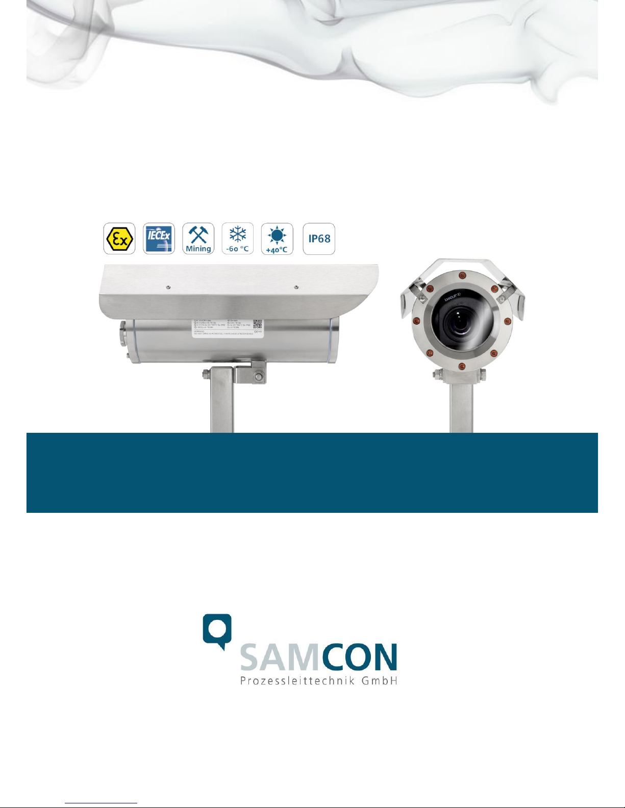
1 Introduction
The ExCam IP13xx Series is a camera system (type 08) manufactured by SAMCON
Prozessleittechnik GmbH which can be used for various applications, preferably within
hazardous areas of the chemical and/or petro-chemical industry, at offshore plants, in
mines, and at biogas plants.
The camera Series is suitable for the usage within the Ex zones 1, 2, 21, and 22 including the gas group IIC (all gases, steams, and fogs including acetylene, hydrogen and
carbon disulphide) and the dust group IIIC (conductive dusts and flammable fibrous material), as well as in mining. Besides the stationary use, the explosion-proof cameras of
theT08 ExCam Series are certified to be also used for mobile applications (hand-held
etc.)
The Ex d stainless steel housing allows additional alloys, a powder coating, or coats of
varnishes in different RAL colors as well as various mechanical accessories in order to
extend the resistance towards extreme environmental conditions (salt water, acid, solar
radiation, high mechanical strains etc.). Due to the usage of high-quality PTFE sealings,
not only the protection level IP68 is reached but also the chemical resistance is maximized.
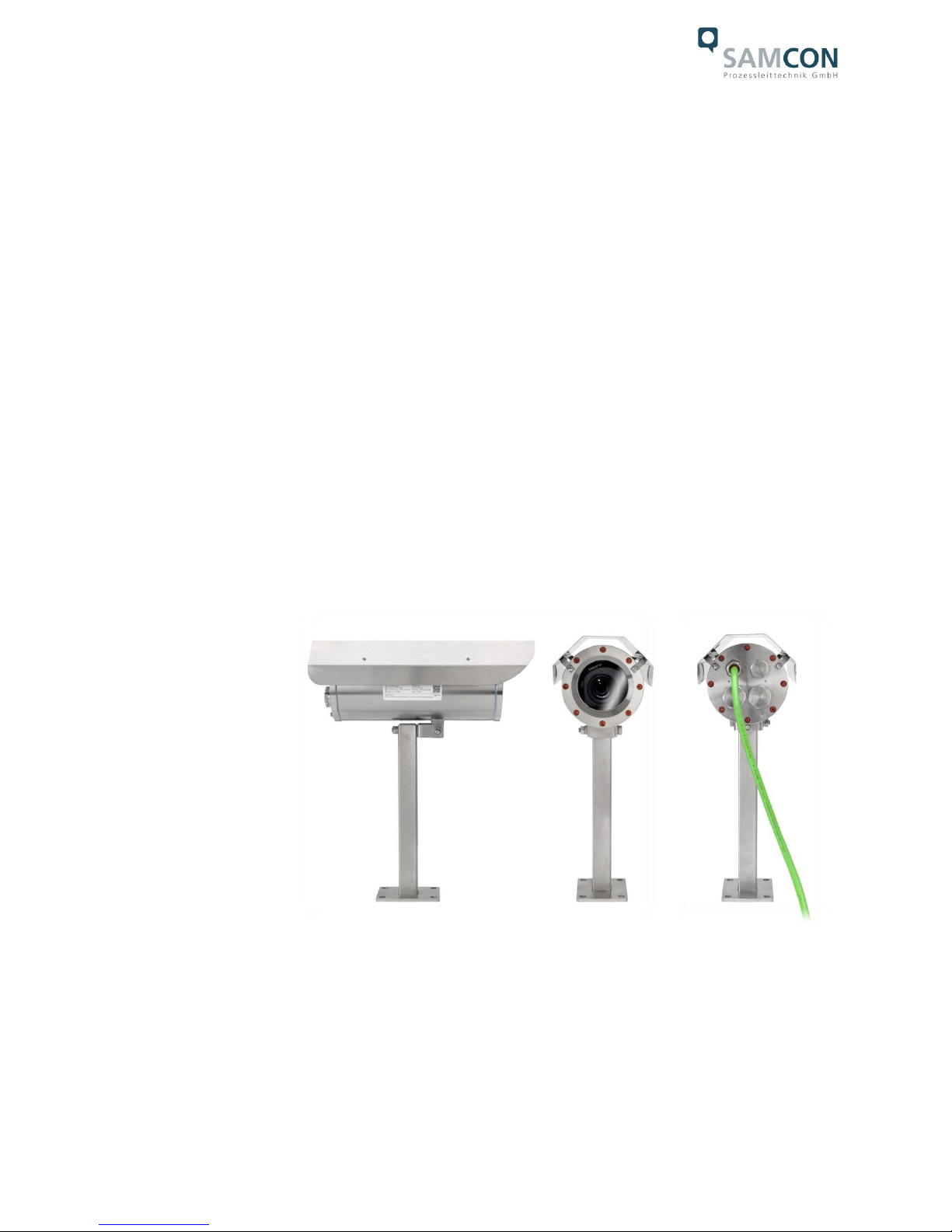
Figure 1.1 – ExCam IP13xx Series with wall mount bracket and roof

Doc.-ID: 141021-PT08BA-TG-ExCam IP13xx Series_en_rev.03, page 6 of 44
2 Technical Data
2.1 Parameters of the explosion protection
Identification marks according to
Directive 94/9/EG (until Apr 20, 2016):
Directive 2014/34/EU: II 2G (zone 1 and 2)
II 2D (zone 21 and 22)
I M2
Explosion protection (gas): Ex d IIC T6 Gb or
Ex d IIC T5 Gb or
Ex d IIB T6 Gb or
Ex d IIB T5
Explosion protection (dust): Ex tb IIIC T80°C Db IP68 or
Ex tb IIIC T95°C Db IP68 or
Ex tb IIIB T80°C Db IP68 or
Ex tb IIIB T95°C Db IP68
Explosion protection (mining): Ex d I Mb
Protection level: IP 68 (IEC /EN 60529)
Transportation / storage temp.(EX): 0° C…+50° C
Ambient temperature (EX)1: -60°C…+65°C (T6)
-60°C…+70°C (T5)
Nominated body: TÜV Rheinland (number 0035)
EC Type Examination: TÜV 14 ATEX 7539 X_1st supplement
IECEx TUR 14.0026X_issue No.1
Additional certificates: EAC-Ex TC_RU_C_DE.MIO62.B.01921
Test protocol ATEX: 557/Ex.539.00/14
Test report IECEx: DE/TUR/ExTR14.0026/00
Quality Assessment Report: DE/BVS/QAR14.0006/00
1
Maximum ambient temperature range relevant for explosion protection might deviate to the maximum functional temperature range.
For maximum functional temperature range (MTBF) see chapter 2.12. Values depending on model

Doc.-ID: 141021-PT08BA-TG-ExCam IP13xx Series_en_rev.03, page 7 of 44
2.2 Electrical parameters of the camera
2.2.1 Axis P1354
Power supply: PoE, IEEE 802.3af class 3
Reference power: ±48 V DC (44...54 V DC)
Maximum power input: 7.2 W
2.2.2 Axis P1357
Power supply: PoE, IEEE 802.3af class 3
Reference power: ±48 V DC (44...54 V DC)
Maximum power input: 7.9 W
2.2.3 Axis P1364
Power supply: PoE, IEEE 802.3af/ 802.3at Type 1 class 3
Reference power: ±48 V DC (44...54 V DC)
Maximum power input: 7.9 W (4.3 W typical)
2.2.4 Axis P1365
Power supply: PoE, IEEE 802.3af/ 802.3at Type 1 class 3
Reference power: ±48 V DC (44...54 V DC)
Maximum power input: 7.9 W (3.6 W typical)
2.2.5 Axis P1365 MkII
Power supply: PoE, IEEE 802.3af/ 802.3at Type 1 class 3
Reference power: ±48 V DC (44...54 V DC)
Maximum power input: 6.8 W (3.6 W typical)

Doc.-ID: 141021-PT08BA-TG-ExCam IP13xx Series_en_rev.03, page 8 of 44
2.3 Electrical parameters of the heating (optional)
Reference power UN: 24 V DC
Nominal power PN: 20 W for type L (T
AMB ≥
-30°)
40 W for type L (T
AMB ≥
-60°)
Attention!
The power consumption of the housing heating is determined by the ambient temperature or, respectively, by the PTC features2 found in the modules’ individual operating
points. In addition, the performance of the PTC load circuit is influenced by the switchingon characteristics of the CB06 circuit board, the load operation of the internal camera
module as well as the convection cooling on the outside (heat dissipation via housing).
Per module, the switch-on power can reach P
max
> 100W! Supply cable fine wire fuses
have to be dimensioned accordingly by the end user. A super-slow (-TT-) trigger characteristic is recommended.
The typical continuous power rating at the low temperature range (T
AMB
-30°C) is
P
(-30°C)
= 12.2 W at a saturated condition
The typical continuous power rating at the artic temperature range (T
AMB
-60°C) is
P
(-60°C)
= 26.8 W at a saturated condition
The typical start-up peak at the low temperature range (1x HP05 heating element) is
I
max
> 4000 mA !
The typical start-up peak at the artic temperature range (2x HP05 heating element) is
I
max
> 8000 mA !
The typical in-rush-duration for I
PTC
< 1000mA per module is tON ≤ 45s
The typical in-rush-duration for I
PTC
< 500mA per module is tON ≤ 120s
(saturated range/ steady current)
2
P
HP05
= KxAxT (K=5.5W/m2)

Doc.-ID: 141021-PT08BA-TG-ExCam IP13xx Series_en_rev.03, page 9 of 44
2.4 System cable SKD02-T
Description: Samcon System Cable Digital (type „SKD02-T“)
for low temperature ranges, data transfer and
power supply of the camera modules M1145
and M1145-L (DIN EN 60079-14: 2014 con-
form)
Sheath color: Yellow-green (GN), similar RAL6018
Ex d marshalling: via the cable gland 13 located on the right
(according to DIN EN 60079-14:2014
[chapter 10.6.2])
At a cable connection length of ≥ 3 m:
(without integrated pressure barrier/ with
elastomer sealing on the outer sheath) e.g.:
„ADE 4F MsNi Type5 - M20x1.5 (CAPRI)“,
with additional strain relief;
At a connection cable length of < 3m:
(with integrated pressure barrier / epoxide
compound grouting of the single conductors
and duroplast/elastomer sealing of the outer
sheath) e.g.: „8163/2 PXSS2K - M20x1.5 (R.
Stahl GmbH)“
Outer diameter: 9.1 ± 0.2mm
Wall thickness: 1.0 ± 0.1mm
Bending radius: 10 x outer diameter at installation
5 x outer diameter after installation
Tensile: Max. 140N
Temperature range: -10° C to +50° C (at point of installation)
-60° C to +80° C (fixed installed)
Conductor design: 4 x 2 x AWG22/1 blank, CAT.6a
Isolation: SFS-PE foamed
Core diameter: 1.52 ± 0.02 mm
Color code: IEC 708-1
Pair shielding: Compound aluminum foil
Shielding: Copper braid, multiple wires 0-10 vz, opt. cov-
erage approx. 85%
Outer sheath: PUR FHF
Characteristics: PUR halogen free, flame resistant (EN 60332-
1-2), UV and ozone resistant, high chemical re-
sistance, EMV shielded
(q.v. www.samcon.eu, data sheet SKD02-T)
3
According to the current standard DIN EN 60079-14:2014, the dimensioning/execution of the cable gland with or without integrated
pressure barrier / compound grouting does not depend anymore on the marked gas explosion group (IIB, IIC) or the Ex d pressure
chamber volume (<2000cm3, ≥2000cm3) but solely on the length of the suitable connection cable (<3m, ≥3m)

Doc.-ID: 141021-PT08BA-TG-ExCam IP13xx Series_en_rev.03, page 10 of 44
User interface: P(Plug) version: RJ-45 Stecker (EIA/TIA-
568B), e.g. Weidmüller IE-PS-RJ45-FH-BK,
Phoenix Contact VS-08-RJ45-5-Q/IP20 etc.,
10BASE-T/100BASE-TX PoE
K(terminal block) version: about 12 cm stripped:
8 x single conductors twisted pair (solid conductor A=0.33mm2, ø=0.64 mm approx. 6 mm
stripped), 1 x shield (Cu braid tinned 1.5 mm2,
ferule color code according to DIN 46228)
10BASE-T/ 100BASE-TX PoE
2.5 Supply cable (optional)
Description: Ölflex® 440P4 (U.I. Lapp GmbH), power supply
for the PTC heat load circuit as well as for the
electronical regulation of the CB06 for T08 Ex-
Cam with the model key „L“ and „LL“,
(DIN EN 60079-14: 2014 conform)
Sheath color: Silver grey (GY) matt, similar RAL7001
Ex d marshalling: via cable gland 2
5
located on the left (according
to DIN EN 60079-14:2014 [Chapter 10.6.2])
At a cable connection length of ≥ 3 m:
(without integrated pressure barrier/ with
elastomer sealing on the outer sheath) e.g.:
„ADE 4F MsNi Type5 - M20x1.5 (CAPRI)“,
with additional strain relief;
At a connection cable length of < 3m:
(with integrated pressure barrier / epoxide
compound grouting of the single conductors
and duroplast/elastomer sealing of the outer
sheath) e.g.:
„8163/2 PXSS2K - M20x1.5 (R. Stahl GmbH)“
Outer diameter: 7.5 mm
Outer sheath: Polyurethane mixture TMPU according to EN
50363-10-2 / VDE 0207-363-10-2
Bending radius: 12.5 x outer diameter (occasional movement)
4.0 x outer diameter (fixed installation)
4
Further cables available upon request, e.g. „Ölflex® Petro FD 865 CP“ (high resistance against oil and drilling liquids) or „XPLE
Armoured 3 x 2.5“ (extremely robust, particularly designed for offshore environments)
5
According to the current standard DIN EN 60079-14:2014, the dimensioning/execution of the cable gland with or without integrated
pressure barrier / compound grouting does not depend anymore on the marked gas explosion group (IIB, IIC) or the Ex d pressure
chamber volume (<2000cm3, ≥2000cm3) but solely on the length of the suitable connection cable (<3m, ≥3m)

Doc.-ID: 141021-PT08BA-TG-ExCam IP13xx Series_en_rev.03, page 11 of 44
Conductor design: 3G1.5 (0012838), 3 x 1.5 mm2 (ø=1.4 mm),
Fine wired tinned copper strand according to.
IEC 60228 / VDE 0295, class 5, with protective
earth (GN/YE)
Copper index: 43.0 kg/km
Weight: 96.0 kg/km
Tensile strength: 15 N/mm2
Characteristics: Resistant to oil and drilling fluids according to
IEC 61892-4: supplement D, wear and notching
resistant, halogen free (VDE 0472-815) and
flame-retardant according to IEC 60332-1-2, re-
sistant to hydrolysis and microbes, UV re-
sistant, additional testing requirements accord-
ing to IEC 60811, EN 50396 and EN 50396
(q.v. www.samcon.eu, data sheet Ölflex 440P)
Conductor identification code: Black conductors with white numbers with
GN/YE- protective earth according to DIN EN
50334 / VDE 0293-334
Classification: ETIM 5.0 Class-ID: EC 000104, ETIM 5.0 type:
Control cable
Conductor insulation: Thermal Plastic Elastomer (TPE)
Nominal current U0/U: 300/500 V AC/DC
Test voltage: 3000 V
Temperature range: -40°C to +90°C (occasional movement)
-50°C to +90°C (fixed installation)
User interface: P(Plug) version: n/a / upon request
K(terminal block) version: 3x 1.5 mm2 (3G1.5)
Cu strand with ferules (color code according to
DIN 46228). Sheath about 12 cm stripped and
furnished with bend relief / shrink tubing
2.6 Technical specification of the camera module
Note:
Technical details of the internal CCTV module such as light sensitivity, resolution, frame
rate sensor, shutter times, lens details, streaming functions, supported network protocols,
event trigger, storage options, and picture parameter setting via the web interface are
thoroughly provided in the data sheets of the camera manufacturer and not part of the
T08 ExCam user manual.

Doc.-ID: 141021-PT08BA-TG-ExCam IP13xx Series_en_rev.03, page 12 of 44
2.6.1 Axis P1354
User manual:
http://www.axis.com/files/manuals/um_p1354_1463736_en_1505.pdf
2.6.2 Axis P1357
Data sheet:
http://www.axis.com/files/datasheet/ds_p1357_1471705_en_1505.pdf
User manual:
http://www.axis.com/files/manuals/um_p1357_1465567_en-1506.pdf
2.6.3 Axis P1364
Data sheet:
http://www.axis.com/files/datasheet/ds_p1364_1511096_en_1512.pdf
User manual:
http://www.axis.com/files/manuals/um_p1364_1510439_en_1601.pdf
2.6.4 Axis P1365
Data sheet:
http://www.axis.com/files/datasheet/ds_p1365_60562_en_1503_hi.pdf
User manual:
http://www.axis.com/files/sales/um_p1365_1489706_en_1507.pdf
2.6.5 Axis P1365 MkII
Data sheet:
http://www.axis.com/files/datasheet/ds_p1365mkii_60562_en_1603.pdf
User manual:
http://www.axis.com/files/manuals/um_p1365mkii_1489706_en_1604.pdf

Doc.-ID: 141021-PT08BA-TG-ExCam IP13xx Series_en_rev.03, page 13 of 44
2.7 Other technical data
Permitted ambient
temperature (MTBF)6: -10 °C … +50 °C (Type N / P1365)
-10 °C ….+40 °C (Type N / P13xx)
-30 °C … +40 °C (Type L)
-60 °C … +40 °C (Type LL)
Protection level EN 60529/ IEC 529: IP68
Test conditions (>IP67): 24h/ 3m water column,
pH-neutrality, temperature of the liquid medium:
+5° C ≤ T
Water
≤ +20° C.
An additional mechanical protection against wa-
ter jets is recommended
Housing material7 of the pressure resistant enclosure (DIN EN 60079-1: 2008) according
to DIN EN 10027-2: 2015-07 (making system for steel):
Housing material (standard) MNo.: 1.4404 (X2CrNiMo17-12-2),
AISI 316L / V4A
Housing material (optional) MNo.: 1.4301 (X5CrNi18-10),
AISI 304 / V2A
MNo.: 1.4305 (X8CrNiS18-9),
AISI 303
MNo.: 1.4401 (X5CrNiMo17-12-2),
AISI 316 / V4A
MNo. 1.4571 (X6CrNiMoTi17-12-2),
AISI 316Ti / V4A
6
Functional temperature range concerning the operational temperature range of the installed components according to manufacture
declarations (MTBF – meantime ration duration between failures). For ambient temperature ranges relevant for explosion protection
(ATEX, IECEx) see chapter 2.1 – Explosion protection)
7
The available stainless steel materials dispose of different specific characteristics such as mechanical and chemical resistance. It is
possible to optimize the corrosion behavior in highly acidiferous environments or at offshore applications by selecting the applicable
housing material. An electro-polished or powder-coated surface in various RAL colors (standard: RAL7035) is possible

Doc.-ID: 141021-PT08BA-TG-ExCam IP13xx Series_en_rev.03, page 14 of 44
Protective coating8: Standard color RAL7035 (all RAL colors
and special colors possible!), DURALMIT®
2K-PUR structure, type DSPT (isocyanate
netted, polyester modified acrylate resin, fine
structure (1.6…2.0 [mm] nozzle), surface re-
sistance ≤ 9^11[Ω], layer thickness ≤ 0.2 [mm],
screw connections, flat gaskets and cable
glands are excluded from the coating
Additional metallic/non-metallic materials
of the Ex d housing protection system:
Zinced spring steel MNo.: 1.0330, PTFE with
glass microbeads (GYLON® Style 3504 blue),
silicone-coating (Silcoset 105 incl. CureAgent
28), VMQ (silicone), thermos transfer foil made
of polyester (aceton resistant), cable glands
made of brass, nickle-plated (MsNi)
Sight glass material: Borosilicate glass (Ilmadur 10/ I-420)
(DIN7080:2005-05)
Internal materials: Aluminum die cast, zinced (protection housing
of the camera module), polyamide (PA6.6/
PA2000) and polyoxymethylene (POM) isolators and supporting adapters, T08 aluminum
universal adapter (EN AW-ALSi1MgMn), PTCceramics, PUR and additional thermoplastic
plastics, optical and electronical components
etc.
Attention: The Axis module is equipped with an
ML614R battery which supplies the real time
clock (RTC). These lithium button cells (3.0 V)
dispose of 1.2 dimethoxymethane; ethylenglycoldimethylether (EGDME), CAS-No. 110-71-4
8
The protective coating of the housing underlies the explosion protection! Affected are exclusively the outside metal surfaces. The
gaps preventing the transmission of an ignition / threads as well as the sealings remain unaffected. The modification of the housing
surface meets the requirements acc. to DIN EN 60079-0: 2012 chapter 7 – non-metallic housings and non-metallic housing components (UV resistance, temperature index TI or relative heat index RTI-mechanical acc. to ANSI/UL 746B or heat and cold resistance).
The avoidance of electrostatic charges is reached by the surface resistance ≤ 9^11 Ω (max. 50% relative humidity) and the limitation
of the layer thickness to 0.2mm (IIC)/ 2mm (IIB). Due to the surface coating, the thermal value and the convection cooling change.
The maximum permitted power loss feed into the housing is not affected by it!
 Loading...