

SAM Audio PMS Owner's Manual [de]

Bedienungsanleitung
Owner` s Manual
PMS
modular mixing system


Die Aufgabe des Mischpultes
Das Mischpult ist die zentrale Stelle in
der PA, es ist für folgende Aufgaben zuständig: es sammelt sämtliche Signale,
verstärkt sie auf ein gemeinsames Niveau, erkennt dabei Verzerrungen und
zeigt sie an, optimiert die Signale im
Klang, mischt sie zusammen, verteilt sie
gleichzeitig auf verschiedene We g e ,
mischt Effekte dazu, versorgt Kondensatormikrofone mit Spannung, paßt das gesamte Klangbild an die Hallenakustik an,
verhindert Erdschleifen durch symmetrische Anschlüsse, verhindert Rückkopplungen durch entsprechende Monitorklangregelung und verwirrt nicht selten
den Mann (oder die Frau), der (oder die)
es versucht zu bedienen. Dieser möglichen Verwirrung wollen wir entgegenwirken indem wir im Folgenden zunächst
die Grundzusammenhänge erklären, die
wichtigsten Qualitätskriterien erläutern
und dann zur detaillierten Beschreibung
unserer Zeck-Mischpulte übergehen.
The mixing desk´s job
The mixing desk is the central point of
the PA system and is responsible for the
following tasks: it collects all given signals, amplifies them to a collective level,
recognises and indicates distortion, improves on the signal sounds and mixes
them together, simultaneously transmits
them on different routes and mixes effects into them, provides condenser mikes
with voltage, adapts the whole sound to
local acoustics, avoids earthing problems
(loops) by means of balanced connections, avoids feedback by means of separate monitor equalisation and quite
often puzzles the person who is trying to
work it.
We´d like to do something about such
puzzlement by explaining the basic principles, mentioning which quality criteria
were considered and by subsequent detailed descriptions of the Zeck mixing
d e s k s .
Der prinzipielle Aufbau eines Mischp u l t e s
Betrachten wir es zunächst einmal ganz
einfach: in ein Mischpult geht viel rein
und wenig kommt raus. Das ist allerdings
nicht qualitativ, sondern rein quantitativ
gemeint. Im Klartext: das Mischpult faßt
viele Eingangssignale zu einem StereoSummensignal (=Master) zusammen. Allerdings erzeugt das Mischpult keine Leistung, für Leistung ist die Endstufe zuständig. Das Mischpult macht die Vo r v e rstärkung, die zur Aussteuerung der Endstufe notwendig ist.
Das Master-Signal ist das Endprodukt,
das anschließend auf die Endstufen und
damit auf die Boxen gegeben wird. Die
Zumischung von Effekten geschieht im
Mischpult durch Einschleifen von Eff e k tgeräten. Neben dem Mastersignal erzeugt das Mischpult ein Monitorsignal,
das unabhängig vom Mastersignal ist.
Das Monitorsignal gelangt über die Monitorendstufe auf die Bühnenmonitore und
ermöglicht es Sängern, Bläsern, Keyboardern usw. sich selbst besser zu hören.
Die Bühnenlautstärke (Monitor) ist unabhängig von der Saallautstärke (Master)
r e g e l b a r.
Auf das Thema Untergruppen gehen wir
später ein. Das stark vereinfachte Blockschaltbild erklärt den prinzipiellen Aufbau
eines einfachen Mischpultes. Die Anordnung der verschiedenen Regler wurde
aus Gründen der Übersichtlichkeit leicht
g e ä n d e r t .
Basic principles of the mixing
d e s k s
Let´s first of all take a simplified look at
it: a lot goes into a mixer and only a little
comes out. That is, of course, only
meant quantatively and not qualitatively.
In a nut- shell: the mixer combines a
large number of in-going signals in a stereo master signal. It does not produce
any actual power which is provided by
the amplifier. The mixer provides preamplification which is necessary for regulating the main amp performance.
The master signal is the end-product
which subsequently is fed through the
amp to the speakers. Mixing-in of effects
takes place in the mixer by cutting in signals provided by the effects equipment.
Apart from the master signal the mixer
also produces the completely separate
and independant monitor signal which is
transmitted through the monitor amp to
the monitor speakers on stage and enables singers and musicians to hear
themselves better. The volume of the
stage monitors is separately controlled,
independant of the main amp volume.
The subject "subgroups" will be dealt
with later.
The following, highly simplified diagram
explains the basic
structure of a simple mixing desk. The
order of the various controls has been
slightly altered to afford better compreh e n s i o n .

Das Eingangssignal (vom Instrument
b z w. Mikrofon) durchläuft zunächst die
Vorverstärkung (Gain). Hier werden die
unterschiedlich starken Signalquellen auf
ein gleiches Spannungsniveau verstärkt
(ca.0 dB).
Die nächste Station ist die K l a n g r e g e-
lung. Hier können bestimmte Frequenzbereiche des Signales angehoben oder
abgesenkt werden.
Es folgt der Regler für die M o n i t o r-
lautstärke. Dieser Regler sitzt vor dem
Fader (pre fade), d.h. die Monitorlautstärke ist unabhängig von der Fader-(=Master) Laut-stärke. Man kann also jedes
Instrument mehr oder weniger stark auf
den Monitor geben, unabhängig von seiner Saallautstärke.
Als nächstes durchläuft das Signal den
F a d e r. Der Fader legt die anteilige Lautstärke des Einzelkanals im Mastersignal
(=Saalsignal) fest.
Nach dem Fader (post fade) folgt der
Regler für die Effekt-Stärke (Echo, Hall
u s w.).
Ein Kanal kann also nur dann mit z.B.
Echo versehen werden, wenn auch der
Kanalfader auf ist.
Die letzte Station im Eingangskanal ist
der P a n o r a m a - R e g l e r. Er verteilt das
Mono-Eingangssignal auf die Stereo-Masterschienen links und rechts. Das S t e-
reo-Mastersignal ergibt sich also dadurch, daß die Eingangssignale in unterschiedlichen Anteilen nach links oder
nach rechts gegeben werden. Steht der
Panoramaregler auf Mitte, so kommt das
Signal gleichstark auf beide Masterkanäle. Die Masterschienen L + R sammeln sämtliche Eingangssignale. Die
Masterfader L + Rregeln die gesamte
Ausgangslautstärke des Saalsignals.
Die Monitorschiene sammelt die Ein-
gangssignale, die durch Aufdrehen des
Monitorreglers gewollt auf den Monitor
gegeben werden. Der Monitorfader r e-
gelt die gesamte Monitor-Ausgangslautstärke. Die Effektschiene sammelt die
Eingangssignale, die durch Aufdrehen
des Effektreglers gewollt mit einem Effekt versehen werden sollen. Der Regler
"Effekt Send" regelt die gesamte Ausgangslautstärke zum Effektgerät.
Nun sind wir also beim Thema "E i n-
schleifen eines Effektgerätes" angelangt. Hier wird es schon etwas schwierig e r. Versuchen wir, möglichst einfach
diesen Vorgang bei einem Echogerät zu
erläutern. Was am Effekt Send zur Ve r f ügung steht, ist ausschließlich eine S u m-
mierung der Eingangskanäle, die
gerne Echo hätten. Dieses t r o c k e n e
S u m m e n s i g n a l gelangt nun also auf
den Eingang (Input) des Echogerätes.
Das Echogerät nimmt dieses Signal und
verlängert es um bestimmte einstellbare
Zeitintervalle (mehrfach). Diese verzögerten Signale stehen jetzt also am "E f-
fect Out" des Echogerätes zur Ve r f ü-
gung. Man verbindet "Effect out" mit der
"Effect return"-Buchse am Mischpult.
Jetzt gelangt das verzögerte Signal
wieder zurück ins Pult, wird mit dem E f-
f e c t - R e t u r n - R e g l e r in der Lautstärke
eingestellt und wird über den Eff e c t - P a norama-Regler wieder dem M a s t e r s i g n a l
z u g e m i s c h t. Nun ergibt sich eine Ü b e rlagerung des trockenen Master-Signals
mit dem verzögerten Eff e c t - R e t u r n - S i gnal und siehe da: der Sänger singt mit
E c h o. So einfach ist das. Oder doch
nicht? Natürlich, es gibt ja auch noch ster e o - E ffekte. Aber dazu kommen wir spät e r.
Was man noch aus dem vereinfachten
Blockschaltbild gut erkennen kann, ist
die Frage nach Mono und Stereo der
verschiedenen Wege:
Jeder Eingangskanal ist M o n o. We r
also z.B. ein Stereo-Keyboard anschließen will, braucht zwei Eingangskanäle
und muß die beiden Panoramaregler jeweils auf L und R stellen.
Die Monitorschiene und damit der M o-
nitorausgang sind Mono. Die E f f e k t-
schiene und damit der Ausgang zum Ef-
fektgerät (Effect send) sind M o n o. S t e-
r e o - E ffektgeräte erzeugen aus einem
Mono-Eingangssignal ein S t e r e o - E f f e k t -
A u s g a n g s s i g n a l. Die Masterschiene
L/R ist Stereo.
Auf unserem vereinfachten Prinzipschaltbild in Abb.1 sind der Eff e k t - u n d
der Panoramaschalter aus Übersichtlichkeitsgründen unterhalb des Faders positioniert. In der Praxis befinden sich im Interesse der besseren Bedienbarkeit
diese Regler oberhalb des Faders.
The input signals (from instrument or
mike) run firstly through the pre-amplification (gain) where their differing source
strengths are brought up to a common
level (around 0 dB).
The next stop is the e q u a l i s a t i o n
where particular frequency areas can be
streng-thened or diluted.
Next comes the monitor volume con-
t r o l which is pre-fade and therefore independant of the fader (master) volume.
This means that one can channel more
or less of an instrument´s signal over the
monitors, no matter what is coming over
the main speaker system.
The signal then reaches the f a d e r
which conveys the chosen signal
strength of each individual channel to the
master signal (main system). The eff e c-
ts-strength control(echo, delay etc.) is
post-fade. One channel can, for example, only be given echo, when its fader is
open.
The last stop in the input channel is the
panorama control which divides the
mono input signal proportionally between
the stereo master left/right channels, depending on the positon of the rotary contol. If it is centrally positioned (0) the signal is equally divided. All in-going signals
are collected at master L/R and the ma-
ster faders (L/R) control the overall
strength of the final out-going signal.
The monitor route collects all in-going
signals which are deliberately channelled to them through the individual monitor channel controls and the m o n i t o r
f a d e r controls the volume of the overall
and final monitor output signal. The e f-
fects route collects all in-going signals
which have been deliberately effected by
use of the individual channel effects controls. The "e ffects send" control regula-
tes the overall output volume to the effects equipment. This is where we come
to the subject of "cutting
in effects" which is slightly more difficult.
Let´s try to demonstrate, as simply as
possible, how this is done with echo:
what we have at effects send is simply
the sum of all the signals awaiting
echo treatment. This dry signal is relayed to the input on the echo equipment
which then takes it and delays it repeatedly in time intervals which can be regulated. These delayed signals are now
available in the effects equipment o u t-
put. This is then connected to the "e ff e cts return" socket on the mixer and the
delayed signal gets back into the desk.
Its volume is regulated by the "e ff e c t s
r e t u r n" control and mixed in to the master signal over the effects panorama
control. The dry master signal is now
"c o a t e d" with the delayed effects return
signal and suddenly the singer´s voice
has an echo. It´s that simple - or
perhaps not. There are also, of couse,
stereo effects but we`ll get to them later.
What the circuit diagram also clearly
shows is the question of mono and s t e-
reo in the various routes:
Each input channel is mono. If you
want to connect a stereo keyboard, for
example, you need two channels with
the panorama controls set to L and R.
The monitor sectionand the m o n i t o r
o u t p u t is m o n o .
The e ffects sectionand its outputs
(effects send) are m o n o. Stereo effects
change a mono in-going signal into stereo. The master L/R route is stereo.
Our simplified diagram shows the panorama control below the fader for easier
comprehension. In the interests of better
workability they have, in practice, been
placed above the faders.


Was zeichnet ein gutes Mischpult
a u s ?
An ein gutes Mischpult werden folgende
Anforderungen gestellt:
K l a n g q u a l i t ä t
Die Qualität des Mischpultes bestimmt
zu einem hohen Anteil den Klang der
kompletten PA. Das Mischpult muß deshalb hinsichtlich des Schaltungskonzeptes und der Auswahl der Bauteile so ausgelegt sein, daß es den Erfordernissen
des "guten Tons" Rechnung trägt.
● hohe Durchsichtigkeit und Klarheit
des
Klangbildes
● hohe Rausch- und Brummabstände
● korrekte Phasenlage
● hohe Übersteuerungsfestigkeit
nach einem halben Jahr die Regler kratzen oder die Schaltkontakte wegen Korrosion nicht mehr schließen. Die Qualität
der Bauteile und der Verarbeitung muß
bei einem Mischpult auf hohem Standard
sein –auch nach zwei Jahren und vielleicht 2000 Betätigungszyklen darf ein
Regler noch nicht kratzen.
● high transparency and clarity of sound
● high signal-to-noise ratio
● correct phasing
● high headroom
E q u i p m e n t
A good mixer should be equipped with
the following:
I n p u t s / O u t p u t s
All signal sources and additional equipment must be optimally connectable
when it comes to impedances and lev e l s
A u s s t a t t u n g
Ein gutes Mischpult sollte folgendermaßen ausgestattet sein:
Ein- und Ausgänge
Sämtliche Signalquellen und Zusatz-
geräte müssen in Bezug auf Impedanz
und Pegel optimal angeschlossen wer-
den können.
K l a n g r e g e l u n g
Die Klangregelung in den Eingangs-
kanälen muß so komfortabel sein, daß
bei richtigem Gebrauch der Klang ein-
zelner Quellen verbessert werden
kann. Eine einfache Baß- und Höhenre-
gelung reicht hier schon lange nicht
mehr aus. Gut arbeiten kann man z.B.
mit parametrischer Klangregelung oder
mit einem Mehrfach-Equalizer mit Fest-
f r e q u e n z e n .
Effekt und Monitorwege
Ein Effekt- und ein Monitorweg reichen
heute in der Regel nicht mehr aus. Man
sollte die Möglickeit haben, mehrere Ef-
fekt-Geräte anzuschließen (z.B. Echo
und Hall) und man kann mit z.B. zwei
Monitorwegen unterschiedliche Anteile
auf Front- und Seitenmonitore geben.
U n t e r g r u p p e n
Zum vernünftigen Arbeiten mit
Mehrspur-Bandmaschinen braucht man
ein Mischpult mit Untergruppen. Sie er-
leichtern das Aufnehmen und
Wiedergeben der einzelnen Spuren.
Auch im Live-Betrieb sind sie nützlich:
Man kann mehrere Quellen auf eine
Untergruppe zusammenfassen und hat
so die Möglichkeit, mit einem Fader
z.B. die Lautstärke des gesamten
Schlagzeugs zu regeln.
M a s t e r s e k t i o n
Zu einer guten Mastersektion gehören
mehrere Effekt-Returns, Klangregel-
möglichkeiten in den Monitor- und Ma-
stersummen (z.B. Inserts), Vo r h ö r e i n-
richtung (PFL Pre-Fade-Listening),
Talkback-Einrichtung, Ta p e - A n s c h l u ß .
Ve r a r b e i t u n g s q u a l i t ä t
Die beste Ausstattung hilft nicht, wenn
What are the distinguishing qualities
and requirements of a good mixer?
Quality of sound
The quality of the mixer determines, to a
large extent, the sound of the whole PA .
Because of this, the mixer must be designed and fitted so that it can meet the
requirements of a "good sound":
E q u a l i s a t i o n
Equalisation of the input channels must
be so well appointed that, when they
are correctly used, the sound of individual sources can be improved upon.
Simple bass and treble controls are
clearly insufficient for such requirements. The best results are achieved
with parametric equalisation or a graphic equaliser with fixed frequencies.
E ffects and monitor routes
Single monitor and effects routes are
insufficient for todays requirements.
One needs to be able to connect a
number of effects (eg. echo and delay)
and with two monitor routes one can
deliver varying sound levels to the front
and the side monitors for example.
S u b g r o u p s
One requires a mixer with subgroups to
be able to work efficiently with a multitrack recording machine. They simplify
recording and playback of individual
tracks and they can be very useful during life operation:
One can collect various sources onto
one single subgroup and this facilitates,
for example, regualtion of the complete
drums volume on one single fader.
Master section
A good master section requires numerous effects returns, equalisation in the
monitor and sum ouput channels, PFL
(Pre-Fade-Listening), talkback and tape
c o n n e c t i o n s .
Wo r k m a n s h i p
The best equipment is no use, when
after six months of use, the controls become scratchy or switch contacts no longer close, due to corrosion. The quality
of the components and workmanship in
a mixer must be of a high standard even after two years of use and 2000
fully operational activities a control
should not become scratchy.

Das Zeck -Mischpultkonzept
A l l g e m e i n e s
Wir bieten zwei Mischerserien mit jeweils
zwei Linien an:
● Serie FMS mit den Linien FMS 8.0.2
u n d FMS 8.4.2
● Serie PMS mit den Linien PMS 8.4.2
u n d PMS 8.8.2
Beide Serien sind für Live- und Studioanwendungen hervorragend geeignet,
wobei die Schwerpunkte in der unterschiedlichen Ausstattung der Eingangskanäle liegen.
Die Linien bedeuten:
8 . 0 . 2
e r w e i t e r b a r, kleinste Version 8 Eingangskanäle, keine Untergruppen (nur FMS),
größte Version 32.0.2
Eingangsmodulen sind je 4 Kanäle zus a m m e n g e f a ß t .
Als Pult oder im Flightcase
Beide Mischerserien können sowohl als
Pult mit Aluminium-Rahmen und Formseitenteilen als auch fest im Case ein-
g e b a u t geliefert werden.
Bei der Case-Version ist das Flightcase
fester Bestandteil des Mischpultes und
ist im Preis inbegriffen. Grundsätzlich
können die Mischpulte in jeder gewünschten Casegröße gefertigt werden.
Falls keine besondere Größe verlangt
wird, liefern wir ab 16 Eingangskanälen
im vollen Case. Mischpulte mit nur 8
oder 12 Eingängen werden grundsätzlich
im 16er-Case geliefert.
The lines stand for:
8.0.2
The smallest version has 8 inputs, no
subgroups and the inputs are expandable up to 32.0.2
8.4.2
The smallest version has 8 inputs, 4
subgroups and the inputs are expandable up to 32.4.2
8.8.2
The smallest version has 8 inputs, 8
subgroups and the inputs are expandable up to 32.8.2
Modular construction is common to all
lines.
The mixers consist of input, subgroup
and master modules. The input modules
each contain four channels.
8 . 4 . 2
e r w e i t e r b a r, kleinste Version 8 Eingangskanäle und 4 Untergruppen, größte Ve rsion 32.4.2
8 . 8 . 2
e r w e i t e r b a r, kleinste Version 8 Eingangskanäle und 8 Untergruppen (nur PMS),
größte Version 32.8.2
Allen Linien gemeinsam ist:
M o d u l b a u w e i s e
Die Mixer bestehen aus Eingangs-Un-
tergruppen- und Mastermodulen. Bei den
The Zeck mixer concept
We offer two mixer series, each with two
lines:
● FMS series with FMS 8.0.2 and
FMS 8.4.2 lines
● PMS series with PMS 8.4.2 and
PMS 8.8.2 lines
Both series are eminently suitable for
both live and studio use and the main
differences are to be found in the input
channels.
In desk form or in flight case
Both mixer series can be supplied, either in desk form with aluminium frames
and shaped sides, or in flight case form
where the mixer is permanently built in.
The case is a component part and in-
cluded in the price.
Mixers can be delivered in any required case size. If no preference is indicated mixers will be supplied as follows:
16 channels and upward in customised
cases; mixers with only 8 or 12 channels
in 16 channel cases to allow for expansion.

Qualität der Bauteile
Wir verwenden in unseren Zeck-Mischpulten ausschließlich Bauteile allerbester
Qualität: alle Drehregler, Schieberegler
und Schalter kommen von Alps, Japan.
Alps-Bauteile sind in fast allen teuren
Studio-Mischpulten zu finden. Alps-Bauteile garantieren höchste Betriebssicherheit auch nach tausenden von Bedien u n g s - Z y k l e n .
Die elektronischen Bauteile( Tr a n s i s t oren, integrierte Schaltkreise usw.) stammen aus laufender Fertigung namhafter
Hersteller und sind größtenteils selektiert, um ein Höchstmaß an Rauschabstand und Durchsichtigkeit zu erreichen.
Die verwendeten Widerstände bestehen
zu etwa 40% aus M e t a l l f i l m - Ty p e n, wel-
che ein wesentlich geringeres thermisches Rauschen und engere To l e r a n z e n
als Kohleschichtwiderstände besitzen.
Bei dem eingebauten Netzteil verwenden
wir einen streufeldarmen R i n g k e r n-
t r a n s f o r m a t o r, welcher zusätzlich mit
einer Metallhaube abgeschirmt ist. Das
Netzteil ist überdimensioniert und liefert
getrennte Versorgungsspannungen für
O p e r a t i o n s v e r t ä r k e r, Leuchtdioden,
Kopfhörerverstärker und Phantomspeis u n g .
Die Argumente
Die Vorteile unserer Zeck-Mischpulte in
S t i c h p u n k t e n :
● M o d u l b a u w e i s e
● im Flightcase oder als Pult
● E r w e i t e r u n g s m ö g l i c h k e i t e n
● symmetrische Eingänge
● 5 Band-Klangregelung je Kanal oder
4 Band mit 2 x param. Mitten
● 5 bzw. 6 Aux-Wege je Kanal
● Level- und Clip-Control-LED je Kanal
● ON-Schalter je Kanal
● PFL und Solo in allen Kanälen und
We g e n
● Subgruppenmodul mit Aufnahme- und
Wi e d e r g a b e f u n k t i o n
● Vier Effekt-Returns stereo mit LED-
Anzeige
● LED-Zeilen in Master und Monitoren
● Stand by-Schalter für Master
● Tonbandanschluß für Aufnahme und
Wiedergabe in der Master-Sektion
● symmetrische Ausgänge bei Monitor
und Master
● Phantomspeisung Kanal 1-8
und vieles andere mehr.
S e r v i c e a b i l i t y
The buss and supply-current routes are
laid out as flat cables which are connec-
ted to the circuit boards by m u l t i p l u g s .
This solution facilitates the exchange of
individual circuit boards or even whole
modules without soldering. A further advantage for servicing is the removeable
base plate of the Case: When a module
is to be exchanged or the mixer is to be
expanded, the base plate can be screwed off, facilitating easier access to the
multi-plug connections.
G u a r a n t e e
Zeck mixing desks are fully guaranteed
for 2 years, which means that they will
be repaired, free of charge for materials
and work time, at any time within the first
two years after purchase. This is a very
noteable guarantee performance when
one considers that a Zeck FMS 16.4.2
m i x e r, for example, contains the following components:
more than 16,000 soldering and fitting
points; approx. 1m2conductor plate surface; 204 transistors; 80 integrated circuits; 1708 resistors; 239 Alps switches;
24 Alps faders; 56 jack sockets and a
whole lot more.
S e r v i c e f r e u n d l i c h k e i t
Die Summenschienen (Bus-Wege) und
die Stromversorgungsschienen des
Mischpultes sind als F l a c h b a n d k a b e l
ausgeführt. Die Flachbandkabel werden
durch Mehrfachstecker mit den einzel-
nen Platinen verbunden. Durch diese Lösung ist es möglich, ohne Lötarbeiten
einzelne Platinen oder ganze Module
auszuwechseln. Ein weiterer Servicevorteil ist die abnehmbare Bodenplatte:
beim Wechseln eines Modules oder bei
der Erweiterung des Mischpultes kann
die Bodenplatte abgeschraubt werden.
Dadurch erhält man besseren Zugang zu
den Mehrfach-Steckverbindern.
G a r a n t i e
Wir gewähren auf unsere Zeck-Mischpulte 2 Jahre Vollgarantie, d.h. innerhalb
von 2 Jahren nach Kaufdatum werden
unsere Mischpulte ohne Berechnung von
Material und Arbeitszeit repariert. Diese
Garantieleistungen sind bemerkenswert,
wenn man bedenkt, daß z.B. ein ZeckMixer FMS 16.4.2unter anderem folgende Bauteile besitzt:
mehr als 16000 Löt- und Bestückungspunkte; ca. 1m2bestückte Leiterplattenfläche; 204 Transistoren; 80 integrierte
Schaltkreise; 1708 Widerstände; 239 Potentometer ; 200 Schalter ; 24 Fader ; 56
Klinkenbuchsen und vieles mehr.
Um die Qualität der Mischpulte zu sichern, werden neben ausführlichen Zwischen-und Endkontrollen alle Mischpulte
einem 24-stündigen Probebetrieb unterw o r f e n .
Quality of components
Only components of the very highest
quality find their way into Zeck mixing
desks: all rotary controls, faders and
switches are by Alps, Japan.
Alps components are to be found in almost all expensive studio-desks because
they quarantee highest operational efficency even after thousands of hours of
intense activity.
T h e electronic components( t r a n s istors, integrated circuits etc.) are standard products of well known and respected manufacturers and are mainly selected for high achievement in signal-tonoise ratios and transparency. The resistors consist of approx. 40 % metal-film
types which produce considerably less
thermic distortion and narrower tolerances than the carbon-layer variety. The integrated mains adaptor is a large format,
low magnetic interference field, torodial
transformer which is additonally screened by a metal hood. The mains adaptor
is stronger than normal and it delivers
separate supply voltages for op. amps,
LEDs, PFL amplifier and phantom
p o w e r.
All Zeck mixing desks undergo a 24 hour
operational test, intensive intermediate
and final controls to ensure their quality.
A r g u m e n t s
A brief summary of the advantages of
Zeck Mixing desks:
● modular construction
● in flight case or in desk form
● e x p a n d a b i l i t y
● balanced inputs
● 5-band EQ or 4-band with 2 parame-
tric mids per channel
● 5/6 aux routes per channel
● level and clip control LEDs on each
c h a n n e l
● On switch on each channel
● PFL and Solo in all channels and
r o u t e s
● subgroup module with record and
playback functions
● 4stereo effects returns with LED
display
● LED bargraph displays for master
and monitor
● stand-by switch for master
● tape connection for recording and
playback in the master section
● balanced outputs in monitor and
m a s t e r
● phantom power on channels 1-8
...and a whole lot more...
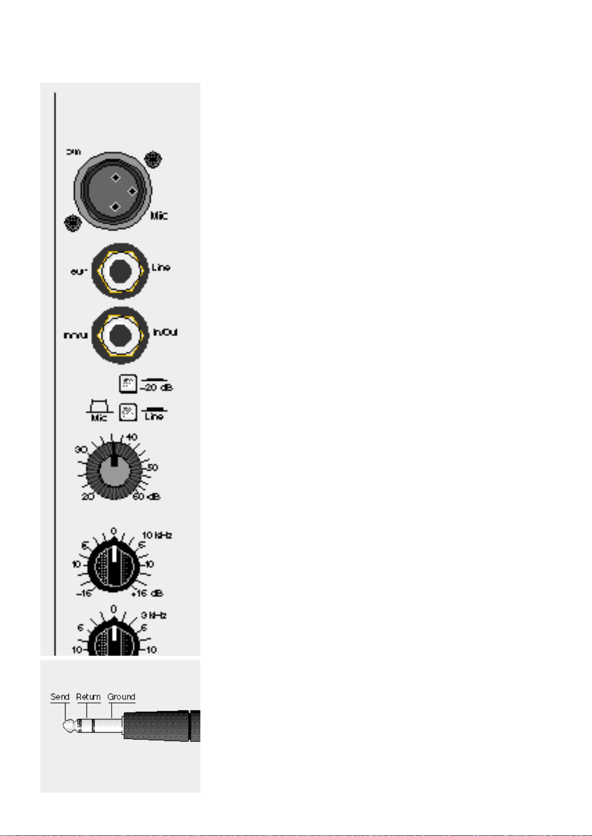
Mic
Der Mic-Eingang ist als XLR-Buchse
ausgeführt. Er ist symmetriert (balanced).
Die Belegung ist:
Pin 3= +Life,
Pin 2= –Life;
Pin 1= Masse.
Max. Empfindlichkeit: 60 dB
Mic
The mic input comes with an XLR
socket and is electronically balanced.
Pin order:
pin 3 = + life,
pin 2 = - life,
pin 1 = ground.
Max. sensitivity: 60dB
Line
Unsymmetrischer Eingang, ausgeführt
als Mono-Klinkenbuchse.
Max. Empfindlichkeit: 40 dB
Eingangswiderstand: >10 kOhm.
In/Out
Diese Stereo-Klinkenbuchse ermöglicht
das Einschleifen von Effektgeräten pro
Kanal. Sie liegt elektrisch nach der
Klangregelung. Die In/Out- Buchse kann
auch als Ausgang (z.B. für Mehrspurmaschinen) genutzt werden. In diesem
Fall wird ein Stereo-Klinkenstecker verwendet, bei dem Ring und Spitze miteinander verbunden sind. Der Ausgang
(Spitze) hat dann Kontakt mit dem Eingang (Klinke), so daß der Signalweg im
Eingangsmodul nicht unterbrochen wird.
Dieser Ausgang bleibt unbeeinflußt vom
Kanal-Fader.
–20 dB
Der Eingangsabschwächer
(–20 dB-Pad) wirkt auf beide Eingänge
(Mic und Line). In gedrückter Position
wird die Eingangsempfindlichkeit um 20
dB herabgesetzt.
Line
Unbalanced input with mono jack-
socket.
Max. sensitivity: 40 dB.
Input resistance: >10 kOhm.
In/Out
This stereo jack-socket allows for the
cutting in of effects on each channel. It
is positioned post-equalisation. The picture shows the contact order. The In/Out
socket can, of course, also be used as
an output (eg. multi-track recording).
For this it requires a stereo jack with
ring and tip connected to each other so
that the signal route in the input module
is not interrupted. This output is not influenced by the channel fader.
–20 dB
The input reducer (–20 dB Pad) works
on both inputs (Mic and Line). In the
pressed position the input sensitivity is
reduced by 20 dB.
Mic/Line
Umschalter zwischen Mic- und Line-
Eingang. In gedrückter Position ist der
Line-Eingang unterbrochen, in nicht gedrückter Position ist der Mic-Eingang
eingeschaltet, der Line Eingang unterbrochen.
Gain
Stufenlose Feinempfindlichkeit. Mit dem
Gain-Regler wird die Eingangsempfindlichkeit des Mixers der angeschlos-
senen Signalquelle (Instrument, Micro
etc.) angepaßt. Er ist dem –20 dB-Pad
nachgeschaltet. Die aufgedruckte dBSkala bezieht sich auf die Empfindlichkeit des Mic-Eingangs. Der Gain Regler
sollte so eingestellt werden, daß die
gelbe Range-LED (neben dem Fader)
leuchtet, aber die rote Clip-Anzeige gerade noch nicht anzeigt. So ist gewährleistet, daß im Eingangs- und Klangregelbereich keine Verzerrungen auftreten. Wenn in der Klangregelung starke
Anhebungen -vor allem im Baßbereicheingestellt werden, wird zwangsläufig
der Gesamtpegel des Signales verändert, so daß die Empfindlichkeit gegebenenfalls nachgeregelt werden muß.
Mic/Line
Switch between Mic and Line input. In
the pressed position the Line input is
operational and the Mic input cut out. In
the raised position the mic input is operational and the Line input is cut out.
Gain
Ungraduated fine control of the input
sensitivity. The gain control adapts the
input sensitivity of the mixer to the
connected signst source (instrument,
mike, etc.). It is positioned post - 20 dB
pad. The dB-scale applys to the mic
input sensitivity. The gain control should
be set so that the yellow Range LED
lights up (next to the fader) but the red
Clip LED does not quite do so. This ensures that no feed back occurs in input
and equalisation. When strong equalisation increases are incurred - paricularly
in the bass range - the general signal levels is inevitably raised so that the sensitvity may have to be reset.
 Loading...