


Bedienungsanleitung
Owner's Manual
Mode d'emploi
R
F 52 EQ
Active Stereo-Controler

Sehr geehrter Kunde,
vielen Dank, daß Sie sich für unseren F 52 EQ entschieden haben. Dieser aktive Hochpaß-Equali-
zer wurde speziell für unsere Miniaturboxen aus der F Serie entwickelt, um deren Übertragungsverhalten im Tieftonbereich weiterhin zu verbessern.
Erreicht wird dieser nach unten erweiterte Frequenzgang durch gezieltes Anheben der Frequenzen unterhalb 50 Hz mit einem steilen Abfall ab 35 Hz, wodurch eine Linearisierung des Frequenzganges und darüber hinaus eine Entlastung des Lautsprechers erreicht wird. Der Anschluß
des F 52 EQ ist äußerst einfach, in den allermeisten Anwendungen kann der Equalizer zwischen
Vorverstärker und Endverstärker geschaltet werden.
Bitte lesen Sie die folgenden Hinweise gründlich durch, um sich mit den Funktionen des F 52 EQ
vertraut zu machen.
Ihr Zeck Team
1. Umstellung auf 110 V Versorgungsspannung
Der F 52 EQ ist ab Werk auf 220 V Versorgungsspannung eingestellt. Sollte ein Betrieb mit 110 V Netzspannung erforderlich sein, kann das Gerät durch
ändern einer internen Verbindung angepaßt werden.
Das Umstellen des Gerätes sollte wegen der damit
verbundenen Risiken nur durch einen Fachmann vor-
alimentation
110 V ac
fig.1
alimentation
220 / 240 V ac
genommen werden :
- ziehen Sie das Netzkabel aus der Steckdose
- lösen Sie die beiden Schrauben “A” (Abb.1)
auf Ober- und Unterseite des Gerätes. Die zwei
verbleibenden Schrauben auf Ober- und Unterseite des Gerätes haben nur dekorative Gründe
und dürfen nicht gelöst werden.
- entfernen Sie den oberen Gehäusedeckel
- lösen Sie die Klemmschraube am Anschluß, der
IN
1 1 0 VIN2 2 0 / 2 4 0 V
mit “IN 220 / 240 V” bezeichnet ist (Abb.2),
und klemmen Sie das Kabel in die danebenliegende Schraubklemme, die mit “IN 110 V” bezeichnet ist. Vergewissern Sie sich, daß die
neue Klemmverbindung korrekt ausgeführt ist
fusible de protection
und daß nicht lose Drähte einen Kurzschluß
zwischen beiden Anschlußklemmen erzeugen.
- verschrauben Sie den Deckel wieder auf dem
Gehäuse
fig. 2
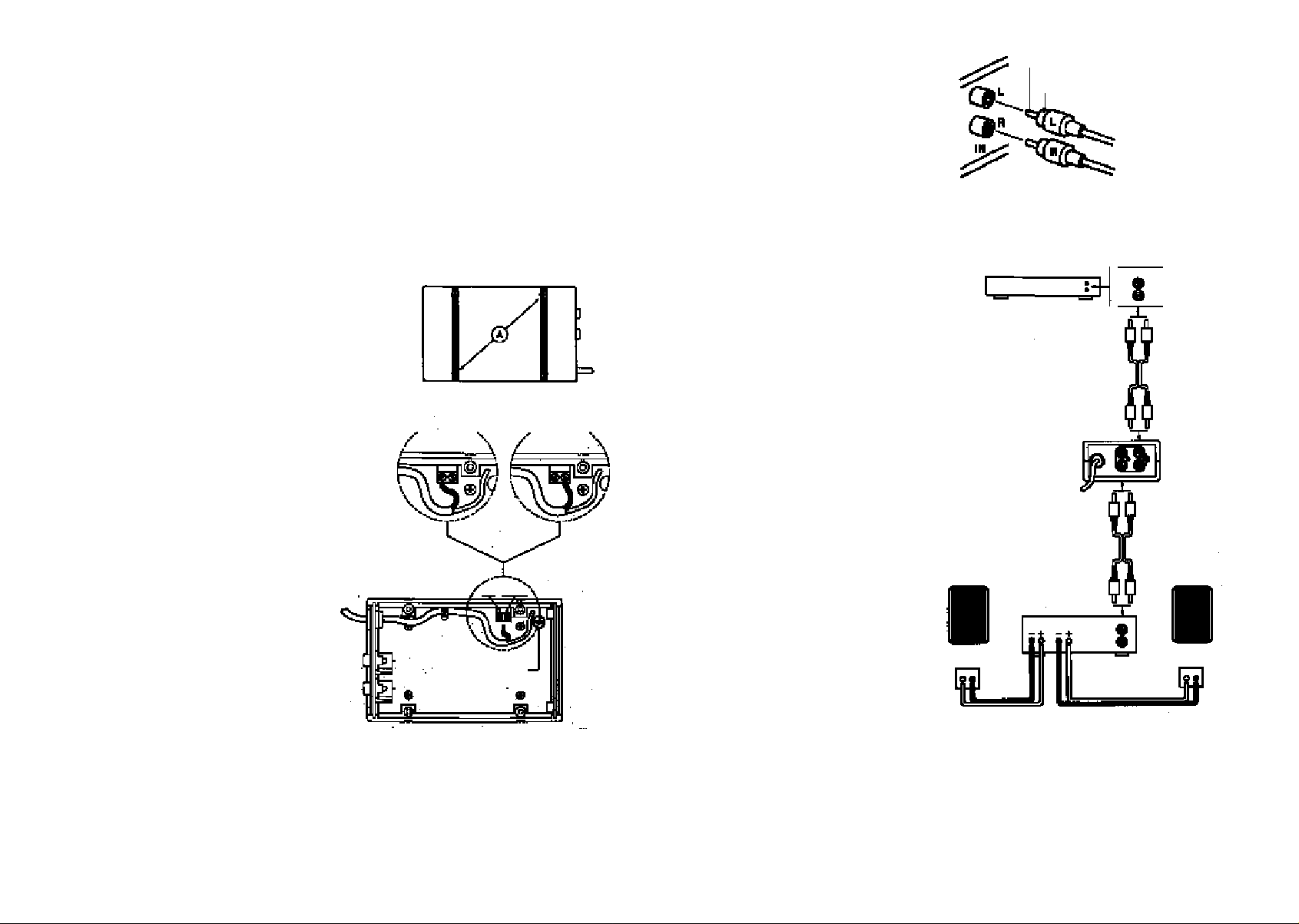
2. Anschluß des F 52 EQ
Auf der Rückseite des Gerätes befinden sich
2 Paare von Cinch-Buchsen, jeweils für die Eingänge und Ausgänge L und R (Abb. 3). Das vorgeschaltete Gerät (Vorverstärker, VorverstärkerAusgang eines Vollverstärkers oder eine sonstige
Quelle) wird mit dem linken und rechten Kanal
an die beiden mit “IN” bezeichneten Buchsen
angeschlossen und darf einen maximalen Ausgangspegel von 3 V Sinus (+12 dB) haben. An
die mit beiden mit “OUT” bezeichneten Buchsen wird der Eingang des Leistungsverstärkers
(oder die Endstufe eines Vollverstärkers) angeschlossen. Für eine Mono-Anlage wird nur e i n e s
der beiden Buchsenpaare benötigt, L oder R.
Abb. 4 zeigt ein Anschlußbeispiel für eine stereophone Anlage mit separatem Vorverstärker
und Leistungsverstärker.
3. Technische Daten F 52 EQ
Frequenzgang..................................35 Hz - 40 kHz
Max. Eingangsspannung.......3 V Sinus (+12 dB)
Eingangsimpedanz.....................................10 kOhm
Max. Ausgangsspannung......6 V Sinus (+18 dB)
Ausgangsimpedanz......................................1 kOhm
Klirrfaktor........................................................0,003%
Grenzfrequenz des Hochpaß-Filters
.................................................................35 Hz / 12 dB
Tiefton-Anhebung ............................6 dB @ 50 Hz
Spannungsversorgung ..110 V od. 220 / 240 V,
50 / 60 Hz
Leistungsaufnahme..........................................1,2 W
Abmessungen............................85 x 44 x 133 mm
Gewicht................................................................350 g
2 Jahre Garantie
F-Serie
Monitor
Anschlußplatte Box
rot
Vorverstärker
schwarz
Signal +
Masse
Leistungsverstärker
Output
L R
Linker Kanal
Rechter Kanal
Output
L
R
L R
L
Out
L
R
L
R
Input
L
R
R
L
R
IN
Abb. 3
F-Serie
Monitor
Anschlußplatte Box
rot
schwarz
Abb. 4

Dear customer,
thank you very much for purchasing our F 52 EQ system. This active highpass equalizer was de-
signed specially for use with our F series miniature speakers to furthermore improve their lowfrequency reproduction.
By selectively boosting the frequencies below 50 Hz with a steep cutoff at 35 Hz, a linearization
of the low-end frequency range is realized, with the positive effect of having less stress put on
the speakers.
Connection of the F 52 EQ is extremely simple, for most applications the unit can be simply
wired between preamplifier and power amplifier.
To become quickly accustomed with the F 52 EQ’s functions, please read the following
instructions carefully.
The Zeck team
2. Connection of the F 52 EQ
The rear side of the F 52 EQ holds two pairs of
RCA phono jacks (Fig.3), one pair for the inputs
(L and R) and one pair for the outputs (L and R).
The L and R outputs of the preceding device (preamplifier or preamp-output of an integrated amplifier), which should have an maximum output
level of 3 V RMS (+12 dB), must be connected to
the two “IN” jacks. The input of the power amplifier is connected to the two “OUT” jacks. For a
monoaural setup, just use one of the channels of
the F 52 EQ (L or R).
Fig.4 shows an example for a stereophonic
setup with separate preamplifier and power
amplifier.
Audio signal
Earth
Preamplifier
Left channel
Right channel
Fig. 3
Output
L
R
1. Rewiring the F 52 EQ for 110 V mains
supply
The F 52 EQ has been factory-prewired for operation with 220 / 240 V mains supply, but can be internally rewired to work with a 110 V mains supply. As this procedure, which is described below, involves opening the unit and working on the mains
wires, it should be left to a qualified service person.
- make sure that the mains cable is disconnected
- loosen the screws “A” (Fig.1) on upper and
bottom side of the unit. The other two screws
on each side are only there for optical reasons
and must not be loosended.
- remove the upper cover of the unit
- loosen the screw of the terminal marked
“IN 220 / 240 V” (Fig.2) and connect the supply cable to the “IN 110 V” terminal instead.
Make sure that the cable is now securely
connected to the “IN 100 V” terminal, and that
there are no loose wires that could cause a
short between the two terminals.
- put the cover back on the unit and re-tighten
the 4 screws
Power supply
110 V ac
Protection fuse
IN
1 1 0 VIN2 2 0 / 2 4 0 V
Fig. 1
Power supply
220 / 240 V ac
Fig. 2
3. Technical specifications
Frequency range.......................35 Hz - 40 kHz
Max. input voltage ...............3 V RMS (+12 dB)
Input impedance ..............................10 kohms
Max. output voltage.............6 V RMS (+18 dB)
Output impedance...............................1 kohm
Distortion............................................0.003%
Cutoff frequency of
highpass-filter.............................35 Hz / 12 dB
Low-frequency boost .................6 dB @ 50 Hz
Mains power supply.......110 V or 220 / 240 V,
50 / 60 Hz
Power consumption ...............................1.2 W
Size .....................................85 x 44 x 133 mm
Weight ...................................................350 g
2 years full warranty
F 52
Monitor
Rear
terminals
red
black
Power
amplifier
Output
L R
Out
L R
L R
Input
L
R
L R
L
R
IN
L
R
F 52
Monitor
Rear
terminals
red
black
Fig. 4
Cher client,
Nous vous félicitons d'avoir choisi notre égaliseur F 52 EQ. Ce filtre passe-haut actif a été spé-
cialement conçu pour nos enceintes miniatures compactes de la série F pour optimiser encore
plus la transmission des fréquences basses. En préaccentuant les fréquences en-dessous de 50
Hz avec une pente raide à 35 Hz, la bande passante est élargie vers le bas de façon à linéariser
la réponse à cette extrémité audio et, en même temps, à apporter un soulagement mécanique au
H P .
L'installation du F 52 EQ se présente extrêmement simple puisque dans la plupart des systèmes
de sonorisation, il suffit de brancher l'égaliseur entre le préamplificatuer et l'amplificateur de
puissance.
Veuillez lire attentivement les instructions suivantes pour vous permettre de vous familiariser
avec les fonctions de l'égaliseur F 52 EQ.
Votre équipe Zeck
1. Alimentation à 110 V
Le F 52 EQ a été ajusté lors de sa fabrication à une
alimentation de 220 V. Si la tension du réseau devait être de 110 V, l'appareil peut être adapté à
l'aide d'un changement de branchement interne.
Cette opération comportant des risques, il est
préférable de ne la faire que par des personnes
Stromversorgung
auf 110 V ac
Abb. 1
Stromversorgung
220 / 240 V ac
compétentes:
- débrancher le câble d'alimentation de la prise de
courant
- dévissez les deux vis "A" (fig. 1) se trouvant sur
le dessus et le dessous du boîtier. Les deux autres
vis visibles sur ces deux faces ont une fonction
exclusivement esthétique et ne doivent surtout
pas être dévissées.
- enlever le couvercle supérieur du filtre
IN
1 1 0 VIN2 2 0 / 2 4 0 V
- après avoir dévissé la vis de la borne marquée
"IN220/240V" (fig. 2), déplacer le câble et
brancher ses conducteurs à la borne marquée
"IN110V". Nous vous recommandons de vérifier
l'exécution correcte du nouveau branchement
Netzsicherung
qu'il n'y ait pas de brins libres qui puissent causer
de court-circuit entre les deux bornes.
- remonter le couvercle sur le boîtier
Abb. 2
2. Branchement du F 52 EQ
Sur le panneau arrière du boîtier se trouvent
deux paires d'embases Cinch pour les entrées et
sorties, "L" correspondant au canal gauche et
"R" au canal droite (fig. 3). L'équipment qui
fournit le signal audio à filtrer (préamplificateur,
sortie préamplificatrice d'un amplificateur intégré ou toute autre source sonore) doit être
branché avec le canal gauche et droite aux deux
bornes "IN" tout en ayant un niveau de sortie
qui ne dépasse pas 3 V RMS (+12dB). Les deux
connecteurs "OUT" doivent être branchés à
l'entrée d'un amplificateur de puissance (ou à la
section de puissance d'un amplificateur intég r é ) .
Une utilisation en mono ne nécessite qu'une
des deux paires de connecteurs: "L" ou "R".
Fig. 4 représente un example de branchement
pour un système stéréophone avec préamplificateur et un amplificateur de puissance.
3. Données techniques du F 52 EQ
bande passante ........................35 Hz - 40 kHz
tension d'entrée max..............3V RMS (+12dB)
impédance d'entrée ..........................10 kOhm
tension de sortie max. ..........6 V RMS (+18 dB)
impédance de sortie............................1 kOhm
taux de distorsion................................0,003%
féquence limite du
filtre passe-haut..........................35 Hz / 12 dB
préaccentuation des graves.........6 dB @ 50 Hz
alimentation..................110 V ou 220 / 240 V,
50 / 60 Hz
puissance absorbée ................................1,2 W
dimensions..........................85 x 44 x 133 mm
poids ......................................................350 g
2 ans de garantie totale
préamplificateur
enceinte compacte
serie F
bornes à l'arrière
de l'enceinte
noir
rouge
signal
masse
amplificateur
de puissance
Output
L R
canal gauche
canal droite
Output
L
R
L R
L
Out
L R
L R
Input
L
R
fig.3
R
L
R
IN
enceinte compacte
serie F
bornes à l'arrière
de l'enceinte
rouge
noir
fig. 4

Zeck Audio
Turnhallenweg 6 • D-79183 Waldkirch • Tel. ...49. (0) 76 81 . 20 04 0 • Germany
 Loading...