


SaMASZ Sp. z o.o.
Poland, 15-161 Białystok, ul. Trawiasta 15
Rok założenia – 1984
NIP 966-159-29-76
tel. (+48) (85) 664-70-31
fax (+48) (85) 664-70-41
e-mail: samasz@samasz.pl
www.samasz.pl
OPERATOR’S MANUAL
REAR DRUM MOWER
Z 010 – 1.65 m
Z 010/1 – 1.85 m
Z 010/2 – 2.10 m
Z 010/4 – 2.10 m
Serial No:
The original instruction
IN005EN010
2012.06.13
EDITION NO 10

ADJUSTING THE MOWER FOR MOWING
DANGER
TURNING THE DRIVE ON,
IF THE MOWER IS NOT
IN WORKING POSITION
DANGER
LIFTING THE MOWER BEFORE
THE MOWING DISCS COME
TO COMPLETE STANDSTILL
DANGER
OPERATING WHEN ANY
PERSON REMAINS IN THE
DANGER AREA OF 50 m
Translated by: Łukasz Łapiński

Operator’s manual
Z 010; Z 010/1; Z 010/2; Z 010/4
Contents Page
Rear drum mower
1. IDENTIFYING THE MACHINE ................................................................................................ 2
2. INTRODUCTION ......................................................................................................................... 2
3. TECHNICAL DATA ..................................................................................................................... 3
3.1. Specifications ........................................................................................................................... 3
3.2. Design and working principle .................................................................................................. 4
3.3. Standard equipment and spare parts ......................................................................................... 5
4. SAFETY ADVICE ......................................................................................................................... 6
4.1. General rules ............................................................................................................................. 6
4.2. Transport................................................................................................................................... 8
4.2.1. Placing the mower onto a transport vehicle ..................................................................................... 8
4.3. Operating elements ................................................................................................................... 9
4.4. The articulated telescoping shaft .............................................................................................. 9
4.5. Residual risk ............................................................................................................................. 9
4.6. Warning decals ....................................................................................................................... 10
4.7. Design and operation of safety breakaway device ................................................................. 13
5. OPERATION OF THE MOWER.............................................................................................. 14
5.1. Attaching the mower to the tractor ......................................................................................... 14
5.2. Preparing the mower for transport .......................................................................................... 15
5.2.1. Standard design ............................................................................................................................. 15
5.2.2. Desing with hydraulic lifting (optional equipment) ...................................................................... 15
5.2.3. Mechanical lock of hydraulic lifting ............................................................................................. 16
5.3. Preparing the mower for transport on public roads ................................................................ 16
5.4. Connecting the articulated telescopic shaft ............................................................................ 17
5.5. Adjustment of conditioner shaft’s position ............................................................................ 18
5.6. Replacement of flails in conditioner’s shaft ........................................................................... 18
5.7. Operation ................................................................................................................................ 19
5.7.1. Standard design ............................................................................................................................. 19
5.7.2. Design with hydraulic lifting (optional equipment) ...................................................................... 19
6. MOUNTING AND ADJUSTMENT .......................................................................................... 20
6.1. Mounting and timing of the knives ........................................................................................ 20
6.2. Replacing the knives............................................................................................................... 20
6.3. Adjusting the cutting unit ....................................................................................................... 21
6.4. Adjusting the cutting height ................................................................................................... 21
6.5. 3-point linkage support chain ................................................................................................. 21
6.6. Maintenance and service ........................................................................................................ 22
6.6.1. Checking the knives and knife holders .......................................................................................... 22
6.6.2. Checking the V-belts tension ......................................................................................................... 22
6.6.3. Daily maintenance ......................................................................................................................... 23
6.6.4. After-season maintenance .............................................................................................................. 23
7. LUBRICATION INSTRUCTION ............................................................................................. 24
8. DEFECTS AND THEIR REPAIRS ........................................................................................... 25
9. DISASSEMBLY AND WITHDRAWAL FROM WORK ....................................................... 26
9.1. Disassembly ............................................................................................................................ 26
9.2. Scrapping ................................................................................................................................ 26
10. WARRANTY CARD ................................................................................................................ 26
11. WARRANTY TERMS.............................................................................................................. 27
11.1. Warranty claims procedures .............................................................................................. 27
11.2. Warranty repairs record ..................................................................................................... 28
- 1 -

Operator’s manual
Z 010; Z 010/1; Z 010/2; Z 010/4
1. IDENTIFYING THE MACHINE
Rear drum mower
Data plate is mounted to the mower’s main frame in the place shown below (Fig. 1).
Data plate includes:
- name of the manufacturer,
- mower’s serial number,
- mower’s type,
- manufacturing date,
- version number,
CAUTION:
For more detailed information concerning the mower ask your dealer or
manufacturer.
Fig. 1. Data plate place
- weight,
- quality management sign,
- CE sign,
- MADE IN POLAND sign,
- barcode.
2. INTRODUCTION
This operator’s manual should be considered as the basic mower’s equipment. If the mower is
handed over to another operator, it should be in working condition and given away along with
operator’s manual and it’s other basic equipment.
Operator’s manual is attached to every machine in order that the operator can familiarize
himself with design, working principles, service and adjustment of the mower. The user of
the mower should be familiar with common safety rules and procedures.
The mower is manufactured according to international safety rules.
Compliance with the warnings in this operator’s manual will ensure safe operation.
Please contact your dealer if you have any queries relating to the operation and service of
the mower.
Operator’s manual remains part of mower’s equipment.
GENERAL WARNING
When operating the mower please comply with the warnings and safety
regulations shown throughout this manual by this safety alert symbol.
CAUTION:
Operation of the mower before reading the operator’s manual carefully as
well as operating by the unauthorised staff, especially by children, is strictly
forbidden.
- 2 -

Operator’s manual
pA
Amax
Cpeak
Z 010; Z 010/1; Z 010/2; Z 010/4
3. TECHNICAL DATA
Rear drum mower
Rotary suspended rear drum mower is designed for mowing the following: common grass,
medick, etc on meadows and on stone free fields as well as forming swath out of these. Meadow
being mowed should be even, previously prepared by rolling and other processing. In lifted rotary
mower with swath conditioners, as a result of difference in speed of moving consequent layers of
grass under influence of flails, process of attrition of plant wax layer occurs. It makes grass drying
process simpler and faster by approx. 30 – 40 %.
WARNING:
It is forbidden to use the mower for purposes other than those listed in this
instruction. Using the mower for other purposes will be classified as use not
according with the intended use and could exclude the manufacturer from
responsibility from any resulting damages. The mower should be used,
serviced and repaired only by persons familiar with its characteristics and
with safety regulations. Unauthorized modification of the mower may release
the manufacturer from responsibility for any resulting malfunctions or
damages.
The Z 010 mower should be used with class 0.9 tractors with 40 HP of power.
The Z 010/1 mower should be used with class 0.9 tractors with 60 HP of power.
The Z 010/2 mower should be used with class 0.9 tractors with 70 HP of power.
The Z 010/4 mower should be used with class 0.9 tractors with 75 HP of power.
3.1. Specifications
Tab. 1. Specifications
Model Z 010 Z 010/1 Z 010/2 Z 010/4
Working width 1.65 m 1.85 m 2.10 m 2.10 m
Number of knives [pcs] 6 (2 x 3) 6 (2 x 3) 8 (2x4) 8 (2x4)
Tractor PTO rpm 540 obr/min 540 obr/min 540 obr/min 540 obr/min
Tractor power required 40 KM 60 KM 70 KM od 75 KM
Working capacity ~ 1.5 ha/h ~ 2.0 ha/h ~ 2.5 ha/h ~ 2.5 ha/h
Transport length 2500 mm 3050 mm 3610 mm 3610 mm
Transport width 1560 mm 1580 mm 1730 mm 1820 mm
Operation width 3160 mm 3330 mm 3920 mm 3920 mm
Conditioner’s working width - - - 700 mm
Weight 400 kg 455 kg 555 kg 690 kg
Nosie level L
PTO shaft requirement 400 Nm 400 Nm 540 Nm* 540 Nm *
Conditioner’s PTO
No. of flails [pcs] - - - 36
Conditioner’s shaft rears
Cutting speed of the knife 90 m/s 88.3 m/s 90.2 m/s 90.2 m/s
Drum rpm 2046 obr/min 1813 obr/min 1610 obr/min 1610 obr/min
Tractor class 0.9 0.9 1.4 1.4
*with overrunning clutch
LpA – noise level related to 8 hour working time. Averaged in time acoustic pressure level corrected by
frequency characteristic A.
L
– maximum value corrected by frequency characteristic A of acoustic pressure level.
Amax
L
– peak level of acoustic pressure corrected by frequency characteristic C.
Cpeak
L
L
80 ± 1 dB
82 ± 1 dB
114 ± 1 dB
- - - 250 Nm
- - - 630 obr/min
- 3 -

Operator’s manual
3.2. Design and working principle
W
1
1 – 3-point-linkage frame,
2 – middle bar,
3 – hydraulic cylinder – extra equipment,
4 – main frame and gearbox,
S
7
Fig. 2. Parts of SaMASZ rear drum mower – flat cover
6
4
5
Fig. 3. Parts of SaMASZ rear drum mower – slanted cover
Rear drum mower
Z 010; Z 010/1; Z 010/2; Z 010/4
3
8
3
2
5 – cutting unit,
6 – cover guard,
7 – drive unit,
8 – mechanical lock.
4
6
5
1
Mower with swath conditioner comprises the following assemblies (Fig. 4):
6
1
5
1 – conditioner’s shaft,
2 – conditioner’s gearbox,
3 – belt gear guard,
2
4
3
Fig. 4. Mower with swath conditioner
4 – conditioner’s drive guard,
5 – working drums guard,
6 – conditioner’s upper guard.
Comprehensively tested construction and proper choice of materials ensure high reliability and
durability of our products.
- 4 -

Operator’s manual
Shaft end with unidirectional right
–
Z 010; Z 010/1; Z 010/2; Z 010/4
3.3. Standard equipment and spare parts
The mowers are sold with the following standard equipment:
warranty card,
operator’s manual with spare parts list,
cutting knives: 1 set,
repair paint – 150 ml,
PTO shaft (Tab. 2),
spare set of flails for conditioner (mower Z 010/4),
spray paint (150 ml).
Optional extra equipment:
warning plates with combined lights and reflectors,
warning triangle.
Rear drum mower
Tab. 2. PTO shafts for SaMASZ rear drum mowers
Mower Power Length Moment
HP mm Nm
Z 010;
Z 010/1
Z 010/2
Z 010/4
Shaft end without clutch –
Connect to tractor.
35 660-900 460 7G3N066CE007007MA
35 660-900 460 7G3N066CE007096MA
35 660-900 620 7G5N066CE007096LA
Fig. 5a. Shaft lubricating instructions and connecting directions Z 010 and Z 010/1
Shaft end without clutch –
Connect to tractor.
Fig. 5b. Shaft lubricating instructions and connecting directions Z 010/2
50h
50h
Symbol
50h
50h
50h
50h
Clutch Manufacturer Notes
Bondioli & Pavesi
Overrunning
right
Overrunning
right
Bondioli & Pavesi
Bondioli & Pavesi
Shaft end without clutch
Connect to the mower.
clutch – Connect to the mower.
- 5 -

Operator’s manual
ft end with unidirectional right
Z 010; Z 010/1; Z 010/2; Z 010/4
Rear drum mower
Shaft end without clutch –
Connect to tractor.
50h
Sha
clutch – Connect to the mower.
50h
Fig. 5c. Shaft lubricating instructions and connecting directions Z 010/4
50h
WARNING:
The frequency of lubrication of the articulated telescoping shaft should be
carefully adhered to. Points shown on Fig. 4 should be lubricated every
8 hours. The articulated telescoping shaft should also be lubricated before
and after longer periods of disuse.
It is possible to use shafts with similar technical parameters from different manufacturers after
consulting SaMASZ.
WARNING:
Before commencing operation, operator’s manual on the mower PTO shaft
should be read thoroughly. In the event of the PTO shaft damage due to its use
for any other purpose than specified in the manual, the SaMASZ company
shall not bear any responsibility for the shaft manufacturer not accepting the
warranty claim. Clutch long-lasting operation with overload of max
10 second period is forbidden.
WARNING:
Additional equipment must be purchased separately.
The manufacturer will equip the mower with connecting elements (brackets and supports) used to
install required lamps and signs. Integrated lamps and reflectors are mounted on the warning board.
4. SAFETY ADVICE
4.1. General rules
The front axle of the driving tractor should be adequately loaded to maintain balance. If
necessary use front wheel weights.
All manipulation of the hydraulic hoist control lever should be made only from the driving seat,
operating the hoist while outside the tractor is forbidden.
In tractors with electro-hydraulic control system (EHR) the hoist is operated with a button
outside the cabin of the tractor. During operation please remain especially cautious.
When changing the mower position from operating to transporting the PTO shaft should be
removed completely or at least on the end connected to the PTO of the tractor.
Operating the mower without covers or the apron is forbidden. The mower should also not be
operated with a damaged or raised apron (there is a danger of the mower throwing hard
objects).
- 6 -

Operator’s manual
Mowing can only be started after the power take-off reaches a nominal speed of 540 rpm.
The power take-off cannot exceed speeds of 600 rpm.
There should be a safe distance between the mower and people, a minimum of 50 m. Utmost
care should be maintained while working in the vicinity of roads and streets.
Any servicing or adjusting of the mower must be done only after the engine and cutting discs
have stopped.
The condition of blade holders must be periodically checked. Any damaged or worn holders
must be replaced.
During transport on public roads all traffic laws regarding lighting and additional equipment for
the mower must be observed. During transport the mower should be equipped with
the removable light board and the triangular safety sign.
WARNING:
Any maintenance or repair of the mower should be done with the tractor
engine off, the cutting bar resting on the ground and all rotating parts must be
During any repair being performed while the mower is lifted on the TPH, the mower should be
secured with a support or a chain so that it does not fall.
The condition of bolts and other connectors should be periodically checked. Operation of
the mower with damaged connectors is unnaceptable.
The regulator line changing the position of the mower should have enough slack and be
properly installed in the cabin of the tractor.
During operation of the mower the Regulation of the Farm Ministry and Food Economy
(Rozporządzenie Ministra Rolnictwa i Gospodarki Żywnościowej) from 12.01.1998 dealing
with safety and hygiene during the operation of tractors, machinery, tools and equipment used
for farming (Dz. U. nr 12/98 poz. 51), should be observed.
The tractor used with the mower should be equipped with a driver's cabin.
The mower cannot be used if the tractor has not been properly balanced.
Never start the mower if it is in the up position.
Never start the mower if people or animals are in the proximity of the mower.
Never lift the tarpaulin apron before the rotating parts of the mower come to a complete stop.
The tractor engine must be turned off.
Observe all safety signs, warnings or warning signs placed on the mower.
Before turning on the tractor make sure that all drives are disengaged and the hydraulic control
lever is in neutral.
Do not leave a running tractor without supervision. Before leaving the tractor turn off
the engine and remove the key from ignition.
It is forbidden to operate the mower in reverse.
Never climb on top of the mower.
Lifting the mower on the hitch of the tractor while the drive is engaged and the discs are
spinning is forbidden.
Acceptable ground incline while operating or transporting the mower is 8°.
Do not get between the tractor and the mower before the equipment has been secured through
the engagement of the parking brake of the tractor.
All inspections of the condition of the mower and any adjustments should be done while
the mower is opened and lowered to the ground.
In case of repairs or adjustments which must be done under the mower it must be secured from
falling using a proper support.
When parts need replacing only original spare parts form the spare parts catalogue should be
used.
Special attention should be paid to the cover-guards of the drive shafts. Never work with
damaged shaft guards.
at rest.
Z 010; Z 010/1; Z 010/2; Z 010/4
Rear drum mower
- 7 -

Operator’s manual
Hydraulic hoses should be periodically checked and in the event of damage or age should be
replaced. Hydraulic hoses should not be used for a period longer than 5 years.
Never repair damaged hydraulic hoses with tape.
While connecting hydraulic hoses to the hydraulic connectors on the tractor make sure
the hydraulic system of the tractor and the mower is not under pressure,
When working with hydraulic systems wear safety glasses and work gloves. Hydraulic oil
under pressure (16 MPa) can penetrate the skin and cause an infection. In the event of such
injury immediately get medical care.
The mower should be stored under cover and in a manner preventing any injury to people and
animals.
Z 010; Z 010/1; Z 010/2; Z 010/4
4.2. Transport
Any changes in the position of the mower can only be done after making sure that there are no
people in the vicinity of the mower (be careful of children).
During time of transport install on the mower the portable light board and the triangular safety
sign identifying a slow moving vehicle.
When transporting the mower it should always be placed in the transporting position. See
point 5.2.
Before the mower which is mounted on the tractor can be placed in the transporting position
please make sure that the power take-off is turned off and all rotating elements have come to
a complete stop.
Driving speed should always be appropriate to road conditions.
Maximum speed of 25 km/h must not be exceeded.
4.2.1. Placing the mower onto a transport vehicle
The carrier and the driver are responsible for safety during the transport of a mower. All
equipment and parts must be secured during transport. The following rules should be observed
when placing a mower onto a transport vehicle:
the mower can be lifted only in places designated for this purpose and labeled with a hook sign.
(Fig. 6),
equipment having a higher lifting capacity than the weight of the mower, shown on
the identification plate, should be used to hoist the mower. This also concerns lines and chains
used to lift the mower,
all folding elements should be secured in the transport position,
Rear drum mower
Transport
Uchwyty transportowe
opening
Fig. 6. Places designated for lifting the mower
the mower should be immobilized on the loading platform of the transporting vehicle so that it
cannot move.
WARNING:
The person operating the hoist is responsible for maintaining a safe
environment during lifting of the mower.
- 8 -

Operator’s manual
Z 010; Z 010/1; Z 010/2; Z 010/4
4.3. Operating elements
Rear drum mower
Before operating the mower check the condition of the blades and blade holders.
Worn or damaged blades or holders should be immediately replaced.
4.4. The articulated telescoping shaft
Use only articulated telescopic shafts recommended by the manufacturer of the mower.
4.5. Residual risk
Despite the fact that the manufacturer of the mower SaMASZ Sp. z o.o. Bialystok, in order to
eliminate danger, assumes responsibility for the design and construction of its mowers, some
elements of risk are unavoidable during mower operation.
Major source of risk follows performance of these operations:
operation of mower by minors as well as not being familiarized with operator's manual,
operation of mower by persons under influence of alcohol or other abusive substances,
not keeping caution while transportation and shifting of mower during operation,
transport of persons remaining on the machine,
presence of persons and animals within the mower operation range,
performing operations related to servicing and adjustment with engine on.
1. The danger of getting caught or pulled in
This danger occurs during changing the positioning of the mower, or working on the mower
while the rotating elements are in operation and with the guards removed.
During operation, maintenance or adjustments to the mower always use protective gloves,
covered footwear, protective clothing without any loose elements, such as belts etc. Always observe
the warnings on the mower.
2. The danger of injury
This can occur during the replacement of working elements with sharp edges. During all
repairs and maintenance always wear protective gloves.
3. The dangers of spurting hydraulic oil
During hydraulic hose connection and disconnection to and from the tractor make certain that
the hydraulic system of the tractor and the mower are not pressurized.
When dealing with a hydraulic system wear safety glasses and protective gloves. Regularly
check the hoses of the hydraulic system.
ATTENTION:
4. Prohibitions
The following activities are prohibited during mower operation:
do not clear, adjust or repair the mower while it is in motion,
never change the order of procedures described in this operating manual,
never operate the mower if it is not in good working condition or has damaged safety aprons,
never place feet or hands near moving parts of the mower,
during repairs or maintenance of the mower use the instructions in this manual, and always
with the drive shaft disconnected from the tractor,
before performing any task concentrate on the task being performed,
never operate the mower under the influence of alcohol, drugs or strong medications,
clothing should neither be too loose or too tight. Any loose elements of clothing can be pulled
into the machine by its moving parts,
the mower must not be operated by children or handicapped people.
Residual risk is the result of inappropriate behavior of the operator.
- 9 -

Operator’s manual
While assessing residual risk the mower is treated as a machine which to the moment of its
manufacture was designed and constructed according to the level of technology used at the time of
its manufacture.
Z 010; Z 010/1; Z 010/2; Z 010/4
Rear drum mower
WARNING:
If the instructions and prohibitions are not adhered to there remains residual
risk.
5. Residual risk assessment
When keeping such recommendations as:
thorough familiarizing with operator’s manual,
no persons remaining on the machine when operating and during drives,
no persons remaining within the mower operation range,
adjustment, maintenance and lubrication of the machine with engine off,
performing repairs of the machine only by skilled persons,
operation of the machine by persons, which are familiarized with operator’s manual,
in the event of the machine protection against children and unauthorized personnel residual risk
when operating the mower may be limited to necessary minimum.
4.6. Warning decals
In the event when avoiding or eliminating professional risk resulting from
exposure to noise is not possible through use of mass safety device or work
organization, the employer (farmer):
1)
makes available personal hearing safety devices if the levels of noise in
working environment exceed 80 dB.
2)
makes available personal hearing safety devices and ensures they are properly
used if the levels of noise in the working environment reach or exceed 85 dB.
CAUTION:
a) all warning decals should be clean and legible,
b) lost or damaged decals must be replaced,
c) please order new decals from your dealer or supplier.
1. N-1
Be extremely careful when PTO
shaft is rotating!
Caution – cutting knives. Approach
during operation is forbidden!
2. N-2
3. N-3
Caution – read the operator’s
manual before putting the mower
into operation!
- 10 -

Operator’s manual
Z 010; Z 010/1; Z 010/2; Z 010/4
Rear drum mower
4. N-4
Caution – while making repairs
the machine must be stopped!
7. N-7
Operating is forbidden when any
person is within the danger area
of 50 m!
5. N-5
Caution – belt transmission, be
extremely careful!
8. N-9
Caution: rotor
6. N-6
Caution – rotating parts
9. N-11
10. N-13 11. N-29 12. N-33
13. N-40
Transport hook for lifting of the
mower
Do not get too close to the hoist of
the tractor during operation of the
14. N-49
15. N-50
Do not get under the mower
hoist
16. N-51
Do not get under the mower
17. N-52
18. N-55
Use protective gloves
- 11 -

Operator’s manual
Z 010; Z 010/1; Z 010/2; Z 010/4
Rear drum mower
19. N-107 20. N-120
21. P-2 22. A-6
Fig. 7a.
Fig. 7b. Points of placing warning signs on mower with swath conditioner Z 010/4 a.o.
Locations
of warning signs (Z 010, Z 010/1, Z 010/2)
- 12 -

Operator’s manual
R
Z 010
R
Z 010/1, Z 010/2
R
Z 010/4
Z 010; Z 010/1; Z 010/2; Z 010/4
4.7. Design and operation of safety breakaway device
Fig. 8. Safety device
Rear drum mower
Safety device (Fig. 8) spring is adjustable, therefore changing the force needed to make safety
device work. In the event of hitting an immovable obstacle one of the safety device flat bars slides
out and disconnects the safety device. After that the mower folds back about 20 degrees (Fig. 9).
The operator has time to shut off the tractor and protect the mower.
Tab. 3. Recommended length of safety device spring
Z 010/4 – 2.10 m with soil breaker,
If the safety device breaks away too easily, tighten up the spring approximately 1 - 2 mm.
DO NOT tighten up too much, because you may prevent the safety device from working and
damage the mower.
Fig. 9. The mower breaks back when the safety device operates
Model Dimension „R” of safety device spring [mm]
Z 010 – 1.65 m 140
Z 010/1 – 1.85 m 135
Z 010/2 – 2.10 m 135
model with polyurethane spring
103
CAUTION:
Do not switch the mower safety breakaway device from transport to
operating position and from operating to transport position with the mower
cutterbar up, connected engine or the tractor engaged neutral.
- 13 -

Operator’s manual
a) In order to switch the mower safety breakaway device from transport to operating position,
the following steps should be taken:
lower the mower cutterbar onto the ground,
unlock the transport clip (!!!!!),
turn the tractor front wheels left most (Fig. 11) and drive backwards until the mower catch
bumper contacts the middle beam,
disconnect the tractor engine and engage neutral or engage hand-brake, so the tractor is
protected from moving,
put the mower safety breakaway device onto pin on the catch and protect with a safety pin
(Fig. 9).
b) In order to switch the mower safety breakaway device from operating to transport position,
the following steps should be taken:
lower the mower cutterbar onto the ground,
disconnect the tractor engine and engage neutral or engage hand-brake, so the tractor is
protected from moving,
remove the safety pin and take the safety breakaway device off from the pin (Fig. 8),
connect the tractor engine, turn the wheels left most and drive the tractor forward until
the transport position clip is locked.
Z 010; Z 010/1; Z 010/2; Z 010/4
Rear drum mower
5. OPERATION OF THE MOWER
5.1. Attaching the mower to the tractor
The mower is connected to the tractor’s 3-point-linkage.
Once the mower is suspended the setting shall be adjusted on even ground with use of
adjustment screw S (Fig. 10) and hangers W of the tractor lower links. The mower discs should be
parallel to the ground; hence this is a condition for sustainable stubble management. Hangers W of
the tractor lower links should be placed on pins A of the mower 3-point linkage frame.
Connect the mower hydraulic hose (optional) to the tractor one-section hydraulic connector.
In order to achieve this entire unit must be weighed first, then drive onto the scale only with
the front axle of the tractor (the mower must be in the transport position, lifted up). If the weight of
the front axle of the tractor is at least 20% of the entire weight of the unit then steering ability has
been preserved. If this is not the case the front axle should be additionally weighed down.
S
W
A
Fig. 10. The mower connected to the tractor
- 14 -

Operator’s manual
b)
Fig. 12
a
Fig. 12
b.
Z 010; Z 010/1; Z 010/2; Z 010/4
5.2. Preparing the mower for transport
Rear drum mower
5.2.1. Standard design
To put the mower into the transport position, please do the following:
mount the 3-point linkage frame onto the tractor links,
position the 3-point linkage frame with beam along the tractor axis (Fig. 11a),
adjust the mower with top link S (Fig. 10), if needed,
disconnect the PTO shaft.
a)
Fig. 11. Mower positions: a) transport position; b) working position
5.2.2. Desing with hydraulic lifting (optional equipment)
To put the mower into the transport position, please do the following:
connect the hydraulic hose for lifting the mower to tractor hydraulic service,
lift the mower with tractor hydraulic lift until the lower lift pins of the mower linkage frame
raise about 500 mm above the ground,
with tractor hydraulic lever pressurise the hydraulic cylinder on the mower and lift the cutting
unit of the machine to the vertical position,
. Side transport position
Rear transport position
CAUTION:
During transport the shut-off valve of mower hydraulic lift should
always be closed – the valve lever in Z position (Fig. 14). It protects
the mower against incidental falling in case of hydraulic failure.
to prevent the mower from falling down close the shut-off valve (Fig. 14) on the hydraulic
cylinder (Fig. 13),
- 15 -

Operator’s manual
O
in the side transport position (Fig. 12a) you can leave PTO shaft connected. In the rear transport
position (Fig. 12b) you have to disconnect PTO shaft.
min. 500 mm
Fig. 13. Mower raised for transport position Fig. 14. Shut-off valve positions
To prepare the mower for transport and to meet safety precautions please:
check carefully the area around the tractor and machine when lifting or lowering the mower,
before lifting the machine into transport position set the machine with the tractor linkage
parallel to the ground.
5.2.3. Mechanical lock of hydraulic lifting
Mechanical lock is placed on hydraulic lifting cylinder to prevent incidental mower’s falling
in its transport position. It is a locking pawl witch is automatically locking in transport position.
Before lowering the mower open the lock by pulling a string connected (Fig. 15).
Fig. 15. Mechanical lock of hydraulic lifting
Z 010; Z 010/1; Z 010/2; Z 010/4
– open
Z – closed
Z
O
Rear drum mower
5.3. Preparing the mower for transport on public roads
To meet safety precautions concerning transport on the public roads in Poland the mower
should be equipped with following devices:
portable warning-light plates, to be mounted on both sides of mower top guard in their holders,
- 16 -

Operator’s manual
Z 010; Z 010/1; Z 010/2; Z 010/4
Fig. 16. SaMASZ mower in the transport position with warning plates
CAUTION:
The warning devices can be ordered from the mower manufacturer.
warning triangle which can be put into holder on top mower guard.
5.4. Connecting the articulated telescopic shaft
When connecting PTO shaft between tractor and mower make sure, that external guard tube
of the shaft is on the tractor’s side.
The PTO shaft plastic guards have to be secured by fastening their small chains to immovable
parts of tractor and mower.
CAUTION:
The PTO shaft should be mounted only during operation time and
disconnected from tractor PTO for transport and service.
CAUTION:
If need be, shorten the PTO shaft according to its operator’s manual given by
the shaft’s manufacturer (Fig. 17).
Fig. 17 Instruktion of PTO shaft ahortening
Rear drum mower
- 17 -

Operator’s manual
CAUTION:
Operate machinery only with the articulated telescoping shafts designated for
use with that machinery. Before strating work chceck if all the covers
(tractor, machinery and shaft) are in place and functioning. Gamage or lost
elements must be replaced with original spares. Check weather
the articulated telescoping ahaft is properly installed. Never get close to
rotating part sit could result in injury or death. During servicing of the shaft
or the machine the engine and the power take-off the tractor must be turned
off. Before operating any machinery carefully read the operating manuals of
the shaft and the machine.
CAUTION:
For Z 010/2 mower use shaft with right overrunning clutch only. See Tab. 2
and Fig. 4b. Use of shaft with no clutch may cause serious damage to
the mower and therefore warranty to be invalid.
Z 010; Z 010/1; Z 010/2; Z 010/4
Rear drum mower
5.5. Adjustment of conditioner shaft’s position
Correct position of conditioner’s shaft in relation to cutting plates enables proper distribution
of grass swath for further treatment. In order to achieve this pay particular attention to placement of
lift, so constant distance of ∼2 cm is kept between ends of flails and surface of cutting plate. In the
event of dense and abundant grass, the tolerance should be increased up to ∼3 cm, so soil breaker is
prevented from clogging. Adjustment of this distance is performed with use of spacers installed
between mower’s frame and conditioner’s lift (Fig. 18).
Adjustment
washers
Fig. 18. Adjustment of conditioner shaft’s position
5.6. Replacement of flails in conditioner’s shaft
If flails worn on normal basis, they must be replaced. Prior to commencing any operation,
on each occasion check condition of bolts, on which flails are set as well as condition of flails
themselves.
CAUTION:
By replacement of crimper’s ram always use a new bolt M12x50, zinc.
cl. 8.8 and a new self-locking nut M12, zinc. cl. 8, tightening
torque 55 Nm.
- 18 -

Operator’s manual
Disassembly of flail encompasses unscrewing nut (M12 oc. kl. 8) with open wrench (19),
taking bolt M12x50 kl. 8.8. out and taking flail out as well. Assembly of new flail is performed in
the opposite way (Fig. 19).
1. Bolt M12x50 kl. 8.8
2. Flat washer ∅12
3. Self-locking nut M12 zinc. cl. 8
4. Ram
5. Flail’s rubber insert
Z 010; Z 010/1; Z 010/2; Z 010/4
Fig. 19. Replacing the crimper’s rams
5.7. Operation
Rear drum mower
5.7.1. Standard design
lower the mower until the sliding saucers come into contact with the ground,
open the locking pawl “Z” (Fig. 20) to allow pin “T” to move in the slot in lifting bar “N”.
It allows the mower to follow the ground contours,
connect PTO shaft between tractor and mower,
slowly engage the PTO clutch and wait until the cutting unit reaches its rated speed,
engage tractor gear and drive slowly into the grass - field.
Z
N
N
Z
T
T
a)
Fig. 20. Positions of locking pawl “Z”: a) transport, b) working
5.7.2. Design with hydraulic lifting (optional equipment)
open the shut-off valve on the hydraulic cylinder (Fig. 14),
move the cutting unit into the working position,
lower the mower until the sliding saucers come into contact with the ground,
connect PTO shaft between tractor and mower,
slowly engage PTO clutch and wait until the cutting unit reaches its rated speed,
engage tractor gear and drive slowly into the grass - field.
b)
- 19 -

Operator’s manual
about 40 cm
Fig. 21. Working position of SaMASZ rear drum mower
Z 010; Z 010/1; Z 010/2; Z 010/4
Rear drum mower
6. MOUNTING AND ADJUSTMENT
6.1. Mounting and timing of the knives
Fig. 22. Timing of the knives on the mowing saucers
6.2. Replacing the knives
Mounting lever
Mounting lever
Mowing saucer
Mowing saucer
Knife
Knife
Knife holder Sliding saucer
Knife holder
Fig. 23. Mounting and replacing the knives
Z010,
Z010/1
Z010/2
Sliding saucer
- 20 -

Operator’s manual
CAUTION:
The cutting edges of the new knives should be directed towards ground.
6.3. Adjusting the cutting unit
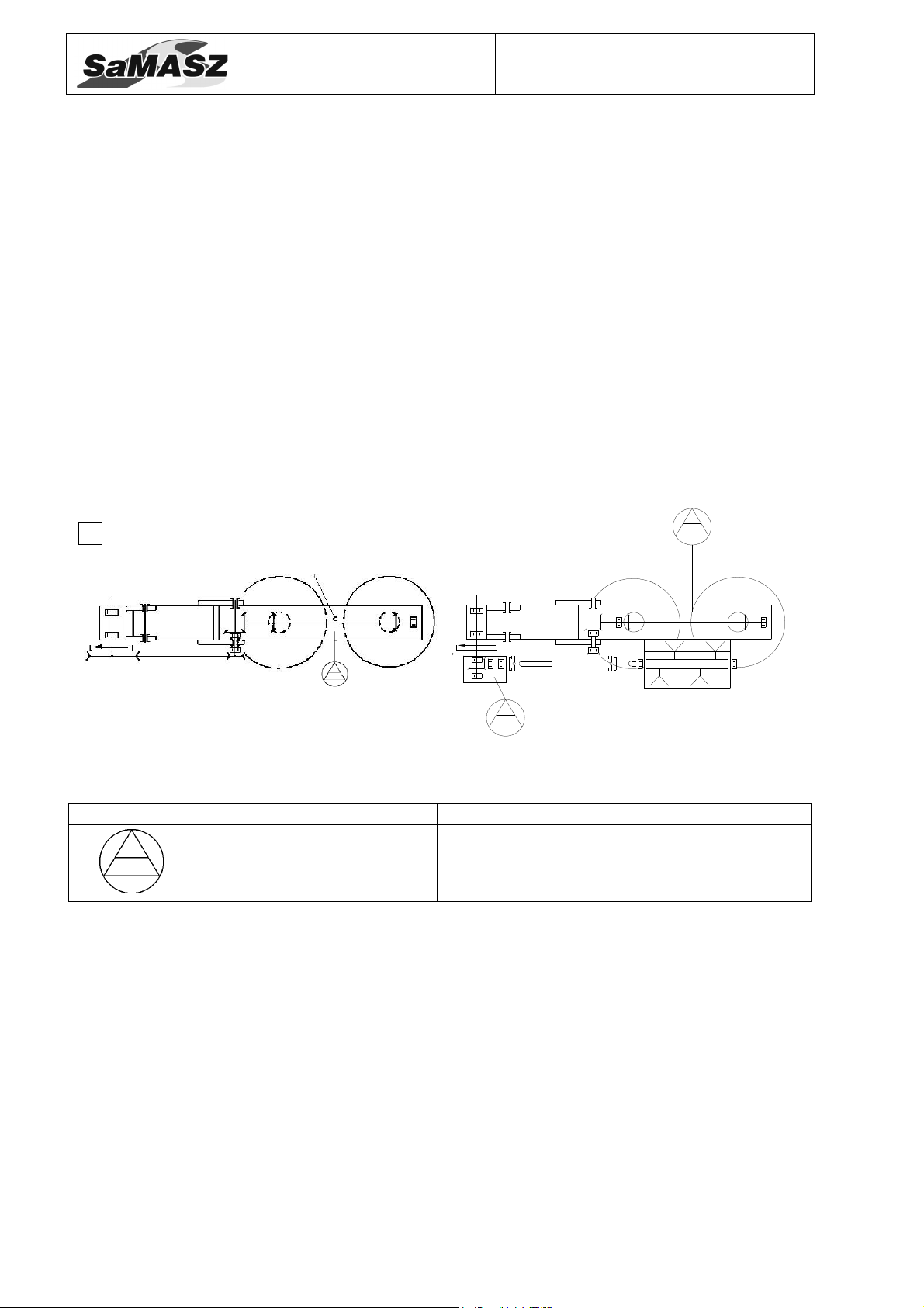
ADJUSTING THE MOWER FOR MOWING
Fig. 24. Adjust the drums level with the ground
Rear drum mower
Z 010; Z 010/1; Z 010/2; Z 010/4
6.4. Adjusting the cutting height
The mower has a factory-set cutting height of 58 - 60 mm. The cutting height can be adjusted
by removing a distance ring (spacer), as shown in (Fig. 25). After removing a new cutting height of
50 - 52 mm is achieved. By putting one additional spacer over the support saucer a cutting height of
66 - 68 mm is obtained. Additional spacers are available (optional extras).
CAUTION:
When mounting additional distance rings longer bolts - M10x35 must be
Sliding saucer
Support saucer
used and tightened to a torque of 55 Nm.
Distance ring
50-52 mm
Fastening bolts
Fig. 25. Adjusting the cutting height by fitting or removing the distance ring
66-68 mm
6.5. 3-point linkage support chain
(Model Z 010/2)
Support chain (Fig. 25) is used to ensure 3-point linkage frame of the mower is always at
the same height, to set the mowing unit parallel to the ground and to relieve the hydraulic lift of
the tractor. If the cutting unit is not set parallel to the ground, the bearings of sliding saucers will be
subject to premature wear.
When connecting mower to the tractor, the hanger plate “A” of support chain should be
disconnected from chain and put on the pin “B” of top link. Then the mower has to be lifted with
hydraulic lift about 40 cm high (Fig. 20). The support chain is then connected to the hanger plate
“A” so that is tensioned when the mower is in the working position.
- 21 -

Operator’s manual
A
Z 010; Z 010/1; Z 010/2; Z 010/4
B
Rear drum mower
Fig. 26. 3-point linkage support chain
6.6. Maintenance and service
6.6.1. Checking the knives and knife holders
All knives should have the same lengths and weights. Always check mower before starting
work for damaged, missing and/or worn blades (knives). Replace blades, if necessary, only in sets.
Make sure all knives in a set are of the same length and weight. The knife holders must not be
damaged or deformed and the knife holder pin, on which the knife is pivoting, shouldn’t be worn
down by more than 50% of its cross-section (Fig. 27). If the knife holder pin is worn too much
and/or the knife holder is worn or deformed on the outside edges, please replace the knife holder
immediately. The riveting of the pin in the knife holder must be checked for safety and quality too.
If the riveting is loose, replace the knife holder.
6.6.2. Checking the V-belts tension
Check the V-belt tension. Their deflection under finger pressure must not exceed 30 mm.
V-belts are tensioned with spring tensioner (Fig. 28) equipped with checking plate (1). Distance
“A” between plate tip and holder should be 0 – 3.0 mm. If the gap is wider the V-belts will be
looser.
When any of the belts are damaged, the complete set must be replaced.
Knife holder pin
Fig. 27. Permissible wear of knife holders
- 22 -

Operator’s manual
1
Z 010; Z 010/1; Z 010/2; Z 010/4
A
Fig. 28. Spring V-belts tensioner, 1 – checking plate. Check dimension “A” should be 0 – 3.0 mm
6.6.3. Daily maintenance
Everyday after work please carry out the following maintenance:
wash the mower with water under pressure after every use, especially between the cutting bard
and discs, because dried mud with grass can cause premature wearing out of the bearings in the
disc assembly or block proper rotation of the assembly,
remove grass and mud,
check all visible units and parts and their connections; tighten all loose bolts and nuts and
replace all damaged and/or worn parts with new genuine ones,
grease PTO shaft tubes with STP grease,
if necessary, lubricate the parts and units according to lubrication instruction.
Rear drum mower
6.6.4. After-season maintenance
At the end of the season the mower should be cleaned, washed and dried. Carefully grease
unpainted surfaces and 3-point linkage pins.
After that the following work should be carried out:
remove any traces of rust and paint the area affected,
loosen v-belts,
check lubrication of gear trough – Fig. 29,
if leaks occur and the plastic cap of air-escape valve (table 1, pos. 14) is damaged, replacement
of the sealing under gear trough cover and of the valve cup are recommended. If water is
discovered in the oil, it must be changed, otherwise the gears, bearings and shafts could be
damaged. Put the replacement sealing carefully into place and tighten cover screws uniformly.
periodically inspect the mower and lubricate moving parts in order to protect them from
corrosion which effects proper operation of the mower,
check hydraulic hoses regularly. Replace any damaged or old hoses. The period of hydraulic
hose utilization should not exceed 5 years from the date of their manufacture printed on
the hose.
- 23 -
Operator’s manual
b)
air-
escape valve with plastic cap
Z 010; Z 010/1; Z 010/2; Z 010/4
7. LUBRICATION INSTRUCTION
Gear trough (gearbox)
The oil level is to be checked periodically through the venting opening on the gear trough.
The oil level should be 15 ÷ 20 mm above the bottom of the trough, when the frame is level. Oil
capacities in the gear box are:
Z 010 – 2.5 litre,
Z 010/1 – 3.5 litre,
Z 010/2 – 4.5 litre.
If the checked oil level is low, please check and eliminate any leaks and fill up to the oil level
required.
Mower’s gearbox and conditioner’s intersecting axis gear
The oil level has to be checked periodically through the venting opening on the gear box.
The oil level should be 15 ÷ 30 mm above the bottom. Oil capacities in the gear boxes are for
mower Z 010/4 – 4,5 litre.
The oil capacity in conditioner's gear should be ~ 0.3 l. Intersecting axis gear of conditioner’s
drive should be filled with gear oil through filler, located in the gear's cover.
a)
Rear drum mower
Tab. 4. Lubrication table
Symbol Oil type Lubrication frequency
Gear oil
80W/90
Fig. 29. Lubrication points a) mowers
Z 010; Z 010/1; Z 010/2, b) mower Z 010/4
Once every 3 seasons
(if working intensively)
- 24 -

Operator’s manual
8. DEFECTS AND THEIR REPAIRS
Defect Reason Repair
Some missing blades Install or replaced blades
Worn blades Replace worn blades
Improperly installed blades
(left – right)
Space between the knife and knife
holder is filled with mud, grass,
The mower mows partially –
leaves furrows between discs
Damaged tractor PTO, does not
Stones between moving parts Stop and remove
Sliding V-belts
power the mower
etc.
Rear drum mower
Z 010; Z 010/1; Z 010/2; Z 010/4
Install blades according to
operating manual
Remove dirt (wash with water
under pressure)
Too low spring tension –
Regulate the spring acc. to
instructions
Worn V-belts – Replace V-belts
Repair PTO
Laid grass Low mowing on each occasion
A mower with roller or scarifier may not mow properly with very
Safety device is working
often without clear reason
Insufficient spring tension
Worn elements of safety device Replace the safety device
Damaged or dirty hydraulic
The mower will not fold up
connections
Damaged tractor hydraulic system
Leaking cylinder
Excesive vibration during
work
Dirty oil in hydraulic unit of the
Damaged PTO shaft
Oil leak in gear Not tight assembly
tractor
low grass or during rain
Adjust spring tension according
to operator’s manual
Replace or clean hydraulic
connections
Check the functioning of
the tractor hydraulic system
Replace oil in hydraulic unit of
the tractor (recommended class
of cleanliness of oil according
to NAS 1638 is minimum
9-10). Purchase repair kit of the
cylinder and replace damaged
sealings
Check the condition of PTO
shaft and if need be replace
Examine tightness and check
oil level.
- 25 -

Operator’s manual
Z 010; Z 010/1; Z 010/2; Z 010/4
9. DISASSEMBLY AND WITHDRAWAL FROM WORK
Rear drum mower
CAUTION:
Before disassembly the mower should be disconnected from the tractor.
9.1. Disassembly
Before starting any repair or service the mower should be cleaned and any grass or dirt
removed. Carefully check nuts and bolts for correct tension and the pins for wear. Replace as
necessary.
9.2. Scrapping
If the mower cannot be repaired anymore, it should be withdrawn from use.
For this purpose oil from gear trough should be drained and delivered to a proper waste
treatment company. Clean the mower parts, dismantle and dispose properly of all plastic parts.
After that, the mower could be sold to breaker’s yard.
10. WARRANTY CARD
REAR DRUM MOWERS
The product quality has been checked and meets the required standards and regulations and is
permitted for use.
CAUTION:
A warranty card without the required information or with corrected or
illegible information – is invalid.
Serial number
Date of manufacture
Manufacturer’s stamp
QC signature
Date of purchase
Dealer’s stamp
Dealer’s signature
- 26 -

Operator’s manual
Z 010; Z 010/1; Z 010/2; Z 010/4
11. WARRANTY TERMS
11.1. Warranty claims procedures
1. The manufacturer guarantees its products against faults in materials or production.
2. Faults or malfunctions of the mower which become apparent within a 24 month period of
the date of purchase will be corrected free of chargé at the buyer’s residence.
3. Any faults or malfunctions should be reported in person, by letter or phone. Repairs will be
performed within 14 days. Warranty repairs are done by the manufacturer or at authorized
service points.
4. Claims for product replacement or returns are accepted and processed by the manufacturer
within 14 days.
5. The following cases are not covered by warranty:
a) operating the mower not according to the operating manual or its intended use,
b) random events or others for which the guarantor is not responsible. transport
damage,
c) natural wear of parts such as: natural wear of parts such as: cutting plates, sliding
skids, intersecting axis gears and parts inside the gearboxes, bushings and sliding
elements, joints, knife holder, cutting knives, V-belts, bearings, lower hubs, safety
curtains, connective elements, etc.,
d) use of non – original parts.
Rear drum mower
6. The Purchaser bears the costs of technical estimation – when the manufacturer finds that
7. The manufacturer has the right to cancel a warranty in following cases:
8. Manufacturer can break the service agreement with immediate effect when the user do not pay
9. Manufacturer does not take compensation responsibility for the loss caused by breakdown of
Such repairs can be performed at the cost of the buyer.
a claimed product is free of defects and a technical report will confirm that.
1. interference of the interior of the mower, changes of its mechanical design or
intentional damages,
2. extensive damage to the mower caused by random event, running into an obstacle or
other for which the guarantor is not responsible,
3. missing required signatures or an attempt to forge them on the warranty card,
4. operating the mower not according with its intended use or operating manual.
receivables according to that agreement in a timely manner and the delay in payment is longer
than 30 days from maturity date. Breaking the service agreement caused by the user makes
simultaneous breaching of the warranty.
the machine during work.
CAUTION:
During your purchase please make sure that the seller carefully fills out
the warranty card including the place and date of purchase and the seal and
signature of the seller. Missing information can cause loss of warranty.
CAUTION:
Please ask your dealer to complete and return the warranty card, otherwise
you may loose your warranty rights.
CAUTION:
After the warranty period repairs can be performed for payment by
authorized service providers designated by the distributor. Providing this
information is the responsibility of the distributor.
- 27 -

Operator’s manual
CAUTION:
The manufacturer reserves the right to alter technical design and
specification without prior notice and without liability.
CAUTION:
The SaMASZ Company is continually working on improvement and
development of all types and models of mowers. For this reason the form,
accessories and technology of delivered products can change. No claims can
be made based on the data, illustrations or descriptions contained in this
manual or the spare parts catalogue.
The SaMASZ is not responsible for printing errors.
11.2. Warranty repairs record
Repair description and changed spare parts:
Date, stamp and signature of repair shop.
Date, stamp and signature of repair shop.
Date, stamp and signature of repair shop.
Rear drum mower
Z 010; Z 010/1; Z 010/2; Z 010/4
- 28 -
 Loading...