


SaMASZ Sp. z o.o.
Established
– 1984
Poland, 16-060 Zabłudów, ul. Trawiasta 1
NIP PL-966-159-29-76
tel. (+48) (85) 664 70 31
fax (+48) (85) 664 70 41
e-mail: samasz@samasz.pl
www.samasz.pl
OPERATOR’S MANUAL
REAR DISC MOWER
KDT 180 - 5' 11"
KDT 220 - 7' 3"
KDT 220 W - 7' 3"
KDT 220 S - 7' 3"
KDT 260 - 8' 6"
KDT 260 W - 8' 6"
KDT 260 S - 8' 6"
KDT 260 SL - 9' 10"
KDT 340 - 11' 2"
KDT 341 - 11' 2"
Serial No:
The original instruction
IN221USA010
17.03.2017
EDITION № 10

Optimum inclination towards the ground is 0 ÷ 5°
to the mowing direction
It is allowed to work in horizontal position.
Different inclination may damage the mower.
DO NOT
TURN THE DRIVE ON
IF THE MOWER IS NOT IN
WORKING POSITION
DO NOT
LIFT THE MOWER
BEFORE THE MOWING
DISCS HAVE COME TO
COMPLETE STANDSTILL
DO NOT
OPERATE WHEN ANY
PERSON REMAINS IN THE
DANGER AREA OF 170′.
Well-proven design with thousands of machines in regular use in many countries and quality
CAUTION:
Keep this manual for future use.
materials ensure high durability and reliability of SaMASZ mowers.

- 1 -
Operator’s manual
1. IDENTIFYING THE MACHINE ........................................................................................................................... 2
2. INTRODUCTION .................................................................................................................................................... 2
3. PROPER AND INTENDED USE ........................................................................................................................... 3
3.1. Technical data ....................................................................................................................................................... 4
3.2. Design and working principle ............................................................................................................................... 5
3.3. Standard equipment and spare parts ..................................................................................................................... 6
4. SAFETY PRECATIONS ......................................................................................................................................... 8
4.1. General safety rules and regulations ..................................................................................................................... 8
4.2. Conditions of mounting mower on tractor .......................................................................................................... 10
4.3. Transport ............................................................................................................................................................. 10
4.3.1. Putting the mower onto another vehicle for transport ................................................................................... 11
4.4. Working parts ..................................................................................................................................................... 12
4.5. PTO shaft ............................................................................................................................................................ 12
4.6. Hydraulic assembly ............................................................................................................................................ 12
4.7. Residual risk ....................................................................................................................................................... 13
4.7.1. Danger of machine entanglement .................................................................................................................. 13
4.7.2. Danger of cutting injury ................................................................................................................................ 13
4.7.3. Danger of injury from liquid ejection out of hydraulic system ..................................................................... 13
4.7.4. Forbidden actions .......................................................................................................................................... 13
4.7.5. Residual risk assessment ............................................................................................................................... 14
4.8. Safety labels and their meaning .......................................................................................................................... 14
5. OPERATION .......................................................................................................................................................... 17
5.1. Attaching the mower to the tractor ..................................................................................................................... 17
5.2. Preparing the mower for transport ...................................................................................................................... 18
5.3. Preparing the mower for transport on public roads ............................................................................................. 19
5.4. Mounting PTO shaft ........................................................................................................................................... 19
5.5. Moving from transport to working position ........................................................................................................ 20
5.5.1. Operating positions of the mower ................................................................................................................. 21
5.6. Preparing the mower for work ............................................................................................................................ 22
5.7. Operation (mowing) ............................................................................................................................................ 22
5.7.1. Essential information concerning mowing .................................................................................................... 23
5.7.2. Design and and operation of safety breakaway device .................................................................................. 24
5.7.3. Mower clogging ............................................................................................................................................ 25
5.7.4. Taking turns over swaths ............................................................................................................................... 25
5.8. Storing ................................................................................................................................................................ 25
5.9. Dismounting mower from tractor ....................................................................................................................... 25
6. MOUNTING AND ADJUSTMENTS ................................................................................................................... 26
6.1. Mounting and timing of the knives ..................................................................................................................... 26
6.2. Replacing the knives ........................................................................................................................................... 26
6.3. Adjusting the cutterbar........................................................................................................................................ 27
6.4. Adjusting the cutting height ................................................................................................................................ 29
6.5. 3-point linkage support chain ............................................................................................................................. 30
6.6. Adjusting the space between tine conditioner’s mask and its shaft .................................................................... 30
6.7. Replacing the conditioner’s tines ........................................................................................................................ 31
6.8. Adjusting force of the prssure of roller conditioner ............................................................................................ 32
6.9. Maintenance and service ..................................................................................................................................... 32
6.9.1. Checking the knives and knife holders .......................................................................................................... 32
6.9.2. Checking the tension of the V-belts .............................................................................................................. 33
6.9.3. Inspection of tension of toothed belt for gears of rollers and conditioner ..................................................... 33
6.9.4. Daily maintenance ......................................................................................................................................... 34
6.9.5. After-season maintenance and storing of machine ........................................................................................ 34
7. LUBRICATION ..................................................................................................................................................... 35
7.1. Cutterbar ............................................................................................................................................................. 35
7.2. Intersecting axis gear .......................................................................................................................................... 36
7.3. Roller conditioner’s gearbox .............................................................................................................................. 36
7.4. Bearings and joints ............................................................................................................................................. 37
8. MALFUNCTION AND THEIR REPAIRS .......................................................................................................... 38
9. DISASSEMBLY AND WITHDRAWAL FROM USE ........................................................................................ 39
9.1. Scrapping ............................................................................................................................................................ 39
10. WARRANTY CARD .............................................................................................................................................. 39
11. WARRANTY TERMS ........................................................................................................................................... 39
11.1. Warranty claims procedures ............................................................................................................................... 39
11.2. Warranty repairs record ...................................................................................................................................... 40
APPENDIX CALCULATING AXIS LOAD ................................................................................................................ 41
Rear disc mowers
KDT

- 2 -
Data plate location
Data plate
Data p
late includes:
- name and adress of the manufacturer,
-
model year,
- CE marking means, that the produce
-
version number,
conforms to 2006/42/EC Directive and
-
machine weight,
harmonized standards,
-
id number,
- machine symbol,
-
barcode.
- date
of manufacture,
Operator’s manual
1. IDENTIFYING THE MACHINE
Rear disc mowers
KDT
Data plate is mounted to the mower’s main frame in the place shown below (Fig. 1).
Fig. 1.
Fig. 2.
NOTE:
For more detailed information concerning the mower ask your dealer or manufacturer.
2. INTRODUCTION
This operator’s manual is essential for safe and proper use of this mower and should be read
before anyone operates this mower. It should be kept near the mower for future use. If the
mower is used by other operator, it should be in working condition and include this
operator’s manual and all other basic equipment.
Operator’s manual is delivered with every machine so that the operator can familiarize
himself with the design, working principle, servicing and adjustment of the mower. The
operator should be familiar with common safety rules and procedures.
The mower is manufactured according to international safety rules.
Compliance with the safety precautions in this operator’s manual will enable safe operation.
Please contact your dealer if you have any queries relating to the operation and service of
the mower.
Operator’s manual remains part of mower’s equipment.

- 3 -
No tilt
3° tilt
5° tilt
"
"
"
.8
"
.4
"
"
"
"
Operator’s manual
3. PROPER AND INTENDED USE
Rear disc mowers
KDT
Mower KDT is equipped with the Perfect Cut cutterbar. The mowing height differences,
depending on the inclination angle of the cutterbar are shown below Tab. 1.
Tab. 1. Mowing height depending on cutterbar's inclination angle
„Perfect Cut” cutting bar
Standard mowing height
Optional heights when using high mowing topping
Optional heights when using high mowing double topping
"
• The front mounted disc mower is intended for mowing green fodder such as grass and alfalfa
on permanent grassland (pastures), on crop fields without rocks, and forming loose rows of cut
fodder. The pasture or field being mown should be even and best if prepared by rolling. In
the event there is a majority of tall grass, the first and second mowing should be done at a
height of 2.4" - 2.8", while with a majority of short grass, at a height of 2". The last mowing
should be done a little higher - at 2.8" - 3.1" from the ground.
• The front mounted disc mower with tine/roller conditioner is intended for mowing green fodder
such as grass and alfalfa on permanent grassland (pastures), on crop fields without rocks, and
forming loose rows of cut forage. As a result of the passing of the layers of the green fodder
through the flails or rollers, the grass stems are broken and a layer of wax is removed. This
facilitates and speeds up the drying process of the fodder by approximately 30 to 40%. The use
of rollers is especially recommended when mowing legumes such as alfalfa Rollers are
particularly recommended for mowing grass legume such as alfalfa. The pasture or field being
mown should be even, best if prepared by rolling. This is especially true of mowers with rollers
as they tolerate rocks with a diameter of a few inches. If a larger stone is picked up stop and
remove it as it could cause damage of the discs. With a majority of tall grasses the first and
second mowing should be done at a height of 2.4" - 2.8", while with a majority of short grass it
should be cut at a height of 2". The last cut should be done a little higher - at 2.8" - 3.1"from
the ground.
Note: Grass, which has not grown much should be mowed with zero angle inclination

- 4 -
Model:
Working width
5' 11"
7' 3"
8' 6"
9' 10"
11' 2"
11' 2"
Number of knives [pcs.]
8 (2 x 4)
10 (2 x 5)
12 (2 x 6)
14 (2 x 7)
16 (2 x 8)
16 (2 x 8)
Tractor PTO rpm
540 rpm
(30 HP)
(50 HP)
(70 HP)
(80 HP)
(90 HP)
(9
0 HP)
3-point linkage category
II
Working capacity
~ 2.0 ha/h
~ 2.5 ha/h
~ 3.0 ha/h
~ 3.5 ha/h
~ 4.0 ha/h
~ 4.0 ha/h
Transport length
3' 11"
Transport width
6' 1"
7' 1"
7' 1"
7' 1"
7' 3" 7' 3"
Working width
11' 6"
13' 9"
15' 1"
16' 9"
18' 1" 18' 1"
W
eight
1213
lbs.
1477 lbs.
1599
lbs.
1730
lbs.
1818
lbs.
1818
lbs.
Cutting speed of the knife
91 m/s
Disc rpm
3250 rpm
Noise level
LpA
101 ± 1 dB
L
Amax
113 ± 1 dB
L
Cpeak
116 ± 1 dB
Model:
Working width
7' 3"
8' 6"
8' 6"
7' 3"
8' 6"
Number of knives [pcs.]
10 (2 x 5)
12 (2 x 6)
12 (2 x 6)
10 (2 x 5)
12 (2 x 6)
Tractor PTO rpm
540 rpm
(60 HP)
(90 HP)
(90 HP)
(60 HP)
(90 HP)
3-point linkage category
II
Working capacity
~ 2,0 ha/h
~ 2,8 ha/h
~ 2,8 ha/h
~ 2,0 ha/h
~ 2,8 ha/h
Transport length
5' 3"
4' 4' 4' 11"
4' 9"
Transport width
7' 7' 7' 7' 7' 3"
Working width
13' 9"
15' 4"
15' 4"
13' 9" 15' 5"
Weight
2073
lbs.
2194
lbs.
2194
lbs.
2095
lbs.
2215
lbs.
Cutting speed of the knives
91 m/s
Disc rpm
3250 rpm
L
Amax
109 ±
1 dB
109 ±
1 dB
L
Cpeak
112 ±
1 dB
112 ±
1 dB
Operator’s manual
WARNING
Use of the mower for purposes other than described above is forbidden. Improper
use can be dangerous and may lead to voiding the warranty. Mower should be
operated and repaired only by persons familiar with its detailed specifications and
with all applicable safety rules and regulations as well as the relative dangers.
Unauthorized modifications to the mower will lead to voiding the warranty.
3.1. Technical data
Tab. 2. Specification of the mower KDT
:
KDT 180 KDT220 KDT260 KDT300 KDT340 KDT 341
Rear disc mowers
KDT
Tractor power required
Tractor power required
22 kW
30 kW
50 kW
60 kW
70 kW
70 kW
KDT 220 S KDT 260 S KDT 260 SL KDT 220 W KDT 260 W
44 kW
66 kW
66 kW
44 kW
66 kW
Noise level L
S – Mowers with tine conditioner W – Mower with roller conditioner
LpA – noise level related to 8 hour working time. Averaged in time acoustic pressure level corrected by
frequency characteristic A.
L
– maximum value corrected by frequency characteristic A of acoustic pressure level.
Amax
L
– peak level of acoustic pressure corrected by frequency characteristic C.
Cpeak
pA
98 ± 1 dB 97 ± 1 dB

- 5 -
2 3
5 6
2
8 9 10
4 –
Cutterbar
11 –
Support legs
Operator’s manual
Rear disc mowers
KDT
3.2. Design and working principle
3-point linkage frame (1) enables attachment of the mower to tractor’s 3-point linkage. Drive
from tractor’s rpm is transmitted through drive unit (3) on the cutterbar (4). Hydraulic cylinder (2)
is used to adjust the mower to working position. It is supplied from outer hydraulics of the tractor.
Main frame, on which the cutterbar (4) is situated, is supported by the springs (7). Swath discs (5)
are mounted on the main frame.
1
7
4
1 – 3-point linkage frame
2 – Hydraulic cylinder with
3 – Drive unit
Fig. 3a. Parts of SaMASZ rear disc mower
5 – Swath discs
6 – Safety curtain
7 – Support springs
3-point linkage frame (1) enables attachment of the mower to tractor’s 3-point linkage. Drive
from tractor’s rpm is transmitted through
intersecting axis gear
(3) on the cutterbar (4). On the
cutterbar, there are discs with two knives each. Apart from that, drive from tractor’s rpm through
chain gear
(9) and PTO shaft (10) is transmitted to tine conditioner (8). Hydraulic cylinder (2) is
used to adjust the mower to working position. It is supplied from outer hydraulics of the tractor.
Main frame, on which the cutterbar (4) is situated, is supported by the springs (7). Swath guides (5)
are mounted on the main frame.
1
7
4
1 – 3-point linkage frame
2 – Hydraulic cylinder with
3 – Intersecting axis gear
4 – Cutterbar
5 – Swath discs
3
Fig. 3b. Parts of SaMASZ rear disc mower with tine conditioner
11
5
6 – Safety curtain
7 – Support springs
8 – Tine conditioner
9 – Chain gear
10 – PTO shaft
11
6

- 6 -
2 3 4 5 6 7 8 9 10
11 –
Support legs
KM ft. in Nm
KDT 180
21 3'-3
' 12'' 270 7G2N086CE007096MA
KDT 260 S/SL/W
Operator’s manual
Rear disc mowers
KDT
3-point linkage frame (1) enables attachment of the mower to tractor’s 3-point linkage. Drive
from tractor’s rpm is transmitted through
intersecting axis gear
(3) on the cutterbar (4). On the
cutterbar, there are disco with two knives each. Apart from that, drive from tractor’s rpm through
Intersecting axis gear
(3) and PTO shaft (10) is transmitted to roller conditioner (8). Hydraulic
cylinder (2) is used to adjust the mower to working position. It is supplied from outer hydraulics of
the tractor. Main frame, on which the cutterbar is situated, is supported by the springs (7). Swath
guides (5) are mounted on the main frame.
1
Fig. 3c. Parts of SaMASZ rear disc mower with tine conditioner
1 – 3-point linakge frame
2 – Hydraulic cylinder with support springs
3 – Intersecting axis gear
4 – Cutterbar
5 – Swath guides
11
6 – Safety guard
7 – Springs
8 – Roller conditioner
9 – Chain gear
10 – PTO shaft
11
3.3. Standard equipment and spare parts
The mowers are sold with the following standard equipment:
warranty card,
operator’s manual with spare parts list,
cutting knives: additional set,
PTO shaft with overrunning clutch,
spray paint (150 ml).
Optional extra equipment:
warning plate with combined lights and reflectors,
warning triangle.
Tab. 3. PTO shaft for rear disc mower
Model Power Lenght Torque Symbol Clutch Producent
KDT 220 ; KDT 260
KDT 300 ; KDT 340
KDT 341
KDT 220 S/SL/W
35 2'12-4'22'' 460 7G4N091CE007096MA
Overrunning
right
BONDIOLI
& PAVESSI

- 7 -
To
nd with overrunning
To be mounted
Operator’s manual
PTO shaft’s end without clutch –
be mounted on the tractor’s side.
Rear disc mowers
KDT
PTO shaft’s e
clutch –
on mower’s side
NOTE:
Lubricate the PTO shaft with high quality multi-purpose grease every 50 shaft
operating hours. If access holes are available, lubricate fittings through access holes.
PTO shafts of other brands with equivalent parameters could be used afer first obtaining SaMASZ
permission.
The mower is equipped with such elements as holders and brackets used to mount warning lights
and plates. Combined lights and reflectors are mounted on the warning plates.
NOTE:
Optional extra equipment should be ordered separately.
Fig. 4. PTO shaft lubrication points. Mounting directions

- 8 -
Operator’s manual
Rear disc mowers
KDT
4. SAFETY PRECATIONS
The following precautions are for your safety. They must be read carefully and
followed by every person who operates or maintains the machine. Failure to follow these safety
precautions could result in serious injury or death to the operator, maintenance person or bystanders
and property damage to the machine and surrounding property.
Safety Signal Words
This manual and the safety labels attached to this equipment utilize signal words that signify safety
hazards with different levels of severity. Below are the words used and the definitions for these
words:
• DANGER indicates a hazardous situation which, if not avoided, will result in death
or serious injury
• WARNING indicates a hazardous situation which, if not avoided, could result in
death or serious injury
• CAUTION indicates a hazardous situation which, if not avoided, could result in
minor or moderate injury
• NOTICE is used to address practices not related to physical injury
4.1. General safety rules and regulations
The following descriptions are for your safety: They must therefore be read
carefully and applied every time you use the machine.
The machine has been designed for use by one single operator.
When using, servicing, repairing, moving or storing the machine, the operator must wear safety
shoes, safety gloves plus ear protection and dust mask if necessary.
During use, the machine may give rise to dust, especially if the soil is dry. You are advised to
use a tractor with a cab fitted with filters in the ventilation system. Failing this, wear a dust
mask with filter to protect your respiratory tract.
Front axis of the tractor should be weighted to keep the balance. If need be, use front wheel
weights.
In order to keep steering conditions, impact on front axis should be at least 20% of the complete
tractor.
Be extremely careful whenever using hydraulic lift lever or buttons. Any operation with
hydraulic lift lever should be done from operator’s seat; DO NOT move the lever from outside
of a tractor.
In case of tractors equipped with EHR, operating with hydraulic lift is done by the buttons
mounted outside the tractor’s cabin. When operating be extremely careful.
When switching from mowing to transport position, remove the entire PTO shaft or at least one
end of the shaft from the tractor’s PTO so it cannot turn.
When attaching the mower to a tractor, the operator should wear protective gloves.
DO NOT operate the mower unless all safety guards are in place and operational. In addition,
any damaged protective aprons should be replaced with a new one
DO NOT exceed 600 PTO rpm.

- 9 -
Operator’s manual
No person (except operator) should stand within danger area which is a minimum of 170’
Rear disc mowers
KDT
from any operating part, especially when operating near roads and in areas with stones and
other debris.
machine
Be certain that children and animals are at a safe distance away from the
.
IMPORTANT: Maintenance and adjustment should ONLY be done after the following has
occurred:
tractor’s engine has been stopped
all rotating parts have come to complete standstill (NOTE: cutting knives will
and ignition key has been taken out,
rotate for several minutes after engine is turned off),
the cutterbar is on the ground, and
Never tamper with or remove safety devices on the machine or make them inoperable.
Before starting work and periodically thereafter, replace any damaged, missing and/or worn
knives and knife holders.
When driving on public roads always comply with local traffic regulations, especially those
concerning warning lights.
When the mower is lifted for repair on 3-point linkage, it should be secured against falling by
mechanical support or by chain.
The bolts and other fasteners have to be periodically checked and, if necessary, tightened or
replaced. DO NOT work with damaged or worn fasteners.
Never lift the mower on tractor linkage when the drive is operating and the cutting discs are
rotating.
When operating the mower, the tractor should always be equipped with operator protection that
is required by laws and regulations.
Never start the mower when the mower blades are off the ground.
Before you start the tractor make sure that all drives are turned off and the levers that turn the
hydraulics are in neutral position.
Never leave tractor’s engine running without supervision. Before you leave the tractor, turn off
the engine and remove the key from tractor’s ignition.
DO NOT operate the mower when driving the tractor backwards.
Permissible inclination of the mower on a slope when working and during transport is 8°.
Exceeding this incline can result in mower tipover.
Never stand between tractor and mower unless tractor and mower are secured against moving
by the tractor’s brake.
If any maintenance must be done under an elevated mower, it must be blocked or otherwise
secured against falling.
When the parts of the mower need replacement, use only original spare parts as described in the
spare parts list. Pay particular attention to PTO shaft’s guards and mower’s and tractor’s spline
shaft guards.
Hydraulic hoses are potentially very dangerous. Do the following to minimize any hazards:
Hydraulic hoses should be periodically checked and if any damage to the hoses have
occurred or if they have been used more than 5 years, replace with new ones.
Never use scotch tape to repair hydraulic hoses.
When connecting hydraulic hoses to tractor’s hydraulic connectors, make sure that
the tractor’s or mower’s hydraulic system is not under pressure.
The mower should be stored under a roof and in a way as to not be hazardous bot people or
animals.
In the event of an accident involving this mower in a field or on a road, follow all applicable
first aid procedures and contact SaMASZ technical service.
Mower should be kept clean, so as to avoid danger of fire.

- 10 -
Operator’s manual
Rear disc mowers
KDT
4.2. Conditions of mounting mower on tractor
Prior to the mounting operation, be sure that the tractor and mower hitches are compatible and
that the tractor's hitch load is adequate for the machine which is to be mounted or attached.
Prior to mounting the machine, examine the technical condition of the mower's hitch assembly
and tractor's 3-point linkage.
Use only genuine cotter pins to mount the mower on a tractor.
4.3. Transport
The lifting, handling and transporting operations can be very dangerous unless they are carried out
with the utmost caution. Have all persons not involved in the actual work move away from the area
and limit the zone where the operations are to be carried out. Also make sure that the area in which
the operations take place is clear and that there is a sufficient escape route, i.e. a free, safe zone to
which the operators can quickly move if the load should fall.
The safety hooks and ropes used to lift the machine must be of an adequate carrying capacity.
To minimize the risk of serious injury or death, do the following:
When the machine is converted from the transport position to the work position and vice versa,
you could be pinched or crushed by some of its parts. Take extra care when carrying out these
maneuvers and have all persons keep well clear of the danger zone.
Do not change position of the mower until there are no people or animals around (pay particular
attention to children).
While transporting the mower, put a warning plate with combined lights and reflectors and
warning triangle on the mower.
During transport, always put the mower in its proper and safe transport position. See section 5.3.
Before putting the mower in transport position, make sure that the tractor’s PTO is turned off
and all rotating parts have come to a complete stop.
Do not drive over 25 km/h (15 mph). Drive slower if road conditions are poor, especially on
irregular surfaces or steep slopes.
The behavior of the tractor on the road, such as its turning and braking capacities, are affected
by the implements mounted.
When driving on the road after work, check to make sure that the tires and soil working tools
are clean to prevent the road surface from becoming dirty.
Make sure that the machine is not damaged during transport.

- 11 -
Operator’s manual
Rear disc mowers
KDT
4.3.1. Putting the mower onto another vehicle for transport
The driver and the carrier are responsible for the mower’s transport safety. Equipment and
parts must be secured during transport. To put the mower onto another vehicle in a safe way, please
obey the following rules:
Transport should be done by qualified and specifically trained personnel,
Grab the mower by any lifting devices only in places indicated by hook sign (Fig. 5),
Fig. 5. Transport holders
For mower lifting, use only lifting devices with hoisting capacity larger than mower’s
weight shown in data plate. This also applies to ropes and chains used for lifting,
Do not lift if transport belts, belt suspensions, ropes are damaged. Whenever damage to
these parts occurs, replace with new ones,
When mounting slings, chains, handles etc., always set the machine's center of gravity
properly,
To safely support the machine, use ropes of adequate length so that the angle between them
is no greater than 120°, and the angle between the strand and the vertical is no greater than
60°,
Lift the machine with the utmost caution and move it slowly,
No one should be within the range of action of the lifting equipment when any transporting
operations are being carried out,
Collapsible parts should be blocked in transport position,
When the mower is on the vehicle’s trailer, the machine should be secured against moving.

- 12 -
Operator’s manual
Rear disc mowers
KDT
Fig. 6. Location of centre of gravity on mowers KDT
Tab. 4. Location of centre of gravity
Dimension
[ft in]
KDT 180 KDT 220 KDT 260 KDT 300 KDT 340 KDT 341
Model
A 2′ 5″ 2′ 4″ 2′ 8″ 2′ 4″ 2′ 4″ 2′ 4″
B 5′ 1′ 6″ 1′ 1′ 7″ 1′ 7″
C 2′ 9″ 3′ 2″ 3′ 4″ 3′ 5″ 3′7″ 3′7″
Dimension
[ft in]
KDT 220 S KDT 220 W KDT 260 S KDT 260 SL KDT 260 W
Model
A 2′ 9″ 2′ 9″ 2′ 8″ 2′ 8″ 2′ 9″
B 4′ 5.5″ 8″ 8″ 9″
C 3′ 4″ 3′ 6″ 3′ 5″ 3′ 4″ 3′ 7″
4.4. Working parts
Before operating the mower check knife’s and knife holder’s condition.
Worn or damaged knives or knife holders should be immediately replaced with new one.
4.5. PTO shaft
Before operating, read bar manufacturer's manual placed on the bar. Follow all safety
precautions in that manual.
Use only PTO shafts recommended by mower’s manufacturer with guards in good condition.
In order to operate safely, use only undamaged PTO shafts and shields. Damaged PTO shafts
and shields must be repaired or replaced with new ones before use.
4.6. Hydraulic assembly
Hydraulic assembly is under high pressure. Hydraulic oil under pressure may penetrate skin
and cause serious injury or death. Skin and eyes should be protected when working around this
assembly.
In case of injury caused by a liquid under pressure, call a doctor immediately.
Hydraulic hoses can be connected to the tractor's hydraulics provided that both the tractor’s and
the mower's hydraulic assemblies are not under pressure. To remove the pressure from the
hoses, start the tractor's hydraulic valves several times with the tractor off.

- 13 -
Operator’s manual
When looking for oil leaks, do so safely. Use a cardboard card. Do not touch any potential
Rear disc mowers
KDT
leaks until the entire hydraulic assembly has been relieved of pressure.
Use only hydraulic oil featuring oil purity class 9 - 10 in accordance with NAS 1638.
When using hydraulic hoses:
Avoid stretching the hoses when operating.
Do not allow hydraulic hoses to get deflected.
Do not expose hydraulic hoses to contact with any sharp edges.
If damaged or worn, replace the hoses with new ones.
Useful life for hydraulic hoses is 5 years from their production date.
4.7. Residual risk
Despite the fact that SaMASZ, the manufacturer of the mower, has taken great care in the
design and manufacturing of the mower, certain risks during mower operation and maintenance are
unavoidable. A major source of risk that could result in serious injury or death can occur during the
performance of these operations.
Major source of risk follows performance of these operations:
operation of mower by minors,
operation by individuals who have not read the operator's manual and safety labels,
operation of mower by persons under influence of alcohol or other substances,
not being cautious during transportation and moving mower during operation,
transport of persons who are on the machine,
presence of persons and animals within the mower operation range,
performing servicing and machine adjustments with the engine on.
4.7.1. Danger of machine entanglement
This risk occurs when (1) changing position of a mower, (2) operating near rotating parts, and
(3) working without safety guards. During operation, maintenance and adjustment, always wear
protective gloves, shoes and clothes without loose parts, belts and so on. Always comply with
safety labels placed on the mower.
4.7.2. Danger of cutting injury
This risk occurs during replacement of working parts with sharp edges. During any
maintenance work, always use safety gloves.
4.7.3. Danger of injury from liquid ejection out of hydraulic system
During connection of hydraulic hoses to hydraulic connectors, be sure that tractor’s or
mower’s hydraulic system is not under pressure. Regularly check hydraulic hoses for leaks.
4.7.4. Forbidden actions
During mower’s operation, do not do the following:
never unblock the mower, make any regulations or repairs of the mower while it is in
motion,
never change order of operation and maintenance activities described in operator’s manual,
never operate the mower when it is not in working order or has damaged safety guards,
never get your hands and legs close to rotating parts of the mower,
during repair and maintenance of the mower, always comply with descriptions included in
operator’s manual. Always do these activities when the tractor’s drive is off,
never operate the mower under influence of alcohol, drugs, or strong medicine that impair
your attention,
do not wear clothes or jewelry that are too loose or too tight. Too loose clothing or jewelry
may be pulled in by the rotating parts of the mower,
the mower should not be operated by children or by handicapped people,
When describing residual risk, the mower complies with the state of the art in technology on the
date it was manufactured.

- 14 -
correctness of its usage, if the noise level in work place reach
es or exceeds 85 dB
.
Operator’s manual
Rear disc mowers
KDT
4.7.5. Residual risk assessment
Residual risk occurs from not complying with the instructions and safety precautions. Such risk can
be minimized by doing the following:
thorough familiarizing yourself with operator’s manual,
allow no persons on the machine when operating,
allow no persons within the mower operation range,
adjust, maintain and lubricate the machine with the engine off,
only skilled persons should perform repairs of the machine,
children and strangers must keep away when the machine is operating,
When the risk of exposure to noise cannot be avoided or eliminated by any
protective means or organization of work, the employer (farmer) must:
1) provide the operator with individual means of noise protection if the noise level
in work place exceeds 80 dB.
2) provide the operator with individual means of noise protection and supervise the
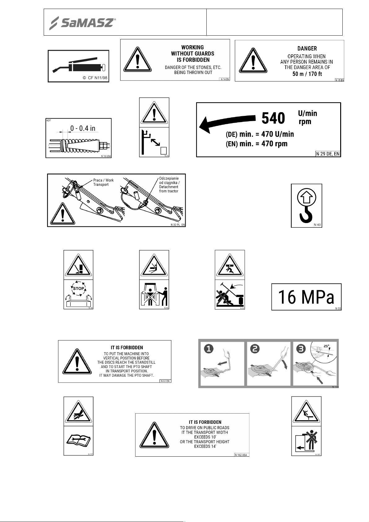
4.8. Safety labels and their meaning
Safety labels are critical to safe use of this mower. They must be read, understood and followed.
Also, be sure that:
All warning decals are clean and legible
All lost or damaged decals are replaced by ordering new decals from your dealer or supplier
All persons using this mower have read the section of this manual explaining the meanings of
these labels
All spare part used for repair of the mower should have all safety labels provided by the
manufacturer.
N-01
Be extremely careful when
PTO shaft is rotating
N-05
CAUTION: belt
transmission, be extremely
careful
N-02
CAUTION: cutting knives.
Approach during operation
is forbidden
N-06
CAUTION: pulling-in
parts
N-03
Read the operator’s manual
before putting the mower
into operation
N-07
Operating is forbidden
when any person is within
the danger area of 170'
N-04
While making repairs the
machine must be stopped
N-09
CAUTION: rotor
- 15 -
Lubrication point
Watch out: power lines
the mower
steering tractor’s lift
Operator’s manual
Rear disc mowers
KDT
N-11
N-16 N-23
N-32 N-40
N-14 N-15
N-29
Transport hook for lifting of
N-48
Stay a way from mower’s
inclination area
N-63 N-109
N-117
Under pressure. Consult
technical manual for
service procedures
N-49
Never stand near tractor’s
3-point linkage while
N-50
Do not stay in the swinging
area of mower’s parts
N-162 N-167
Do not remain on the
machine while driving
N-55
- 16 -
04
48
N-40
N-40
N-187
N-149
N-55
N-109
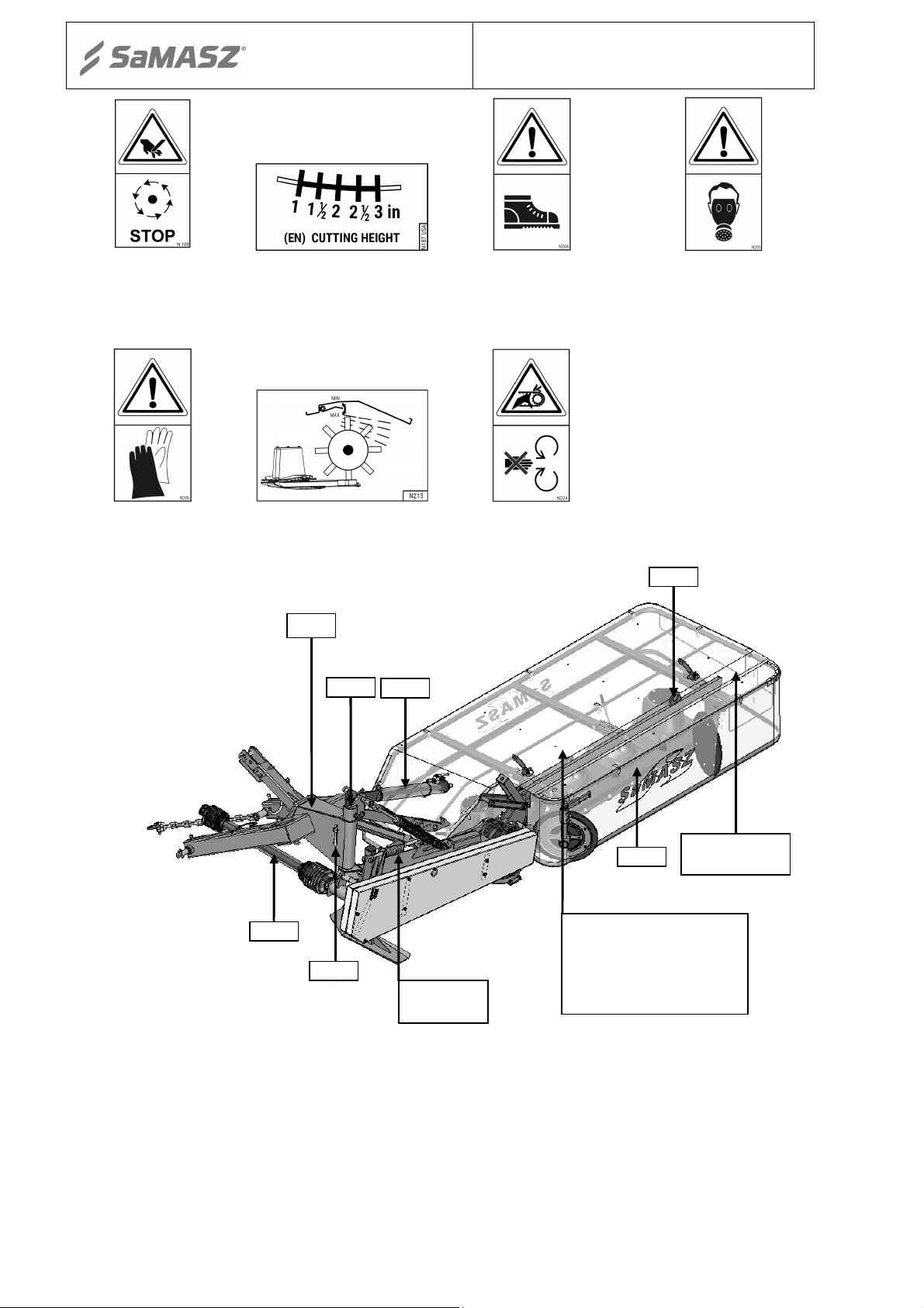
Operator’s manual
Rear disc mowers
KDT
N-168
Do not touch the machine
before the rotating parts
have not come to a
complete standstill
N-206
Use the required Personal
Protective
Fig. 7a. Placement points of warning signs on mower without conditioner
N-187
Cutterbar "Perfect Cut"
N-213
(for KDT S/SL)
N-29
N-05; N-16
N-204
Use the required Personal
Protective
N-224
Do not open and remove
safety guards with motor
operating
N-32
N-205
Use the required Personal
Protective
N-14; N-15
N-63; N-162
N-01 ; N-02 ; N-03 ; NN-06 ; N-07 ; N-23 ; N-
N-49 ; N-50 ; N-117
N-167 ; N-168 ; N-204
N-205 ; N-206 ; N-224

- 17 -
N-149
N-187
04
48
N-205 ; N
-
206 ; N-224
N-109
N-40
N-201
N-40
Operator’s manual
Fig. 7b. Placement points of warning signs on the mower with tine/roller conditioner
N-29
N-05
N-16
N-32
N-14; N-15
N-63 ; N-162
N-09
N-213
Rear disc mowers
KDT
N-01 ; N-02 ; N-03 ; NN-06 ; N-07 ; N-23 ; N-
N-49 ; N-50 ; N-117
N-167 ; N-168 ; N-204
CAUTION:
Any spare part used for repair of the mower should have all warning decals
provided by the manufacturer.
5. OPERATION
WARNING:
Before beginning to use this machine, do the following:
- Read manual, especially safety precautions in section 4.
- Make sure you are familiar with all controls and functions.
- Make sure all safety devices are in place and working. Fix or replace if not
working or damaged.
- Replace protective cover if damaged.
5.1. Attaching the mower to the tractor
WARNING:
-
Only hitch and unhitch machine on a flat surface with compact dirt.
- Keep everyone away from area between mower and tractor.
- Be careful near link road zone of tractor's rear power lift. Contains sharp parts.
Mower’s frame is adjusted to be attached to the tractors with 3-point-linkage (Fig. 8). The mower
has been attached, adjust (on the flat ground) the mower’s position by means of top S and lower W
links (Fig. 8). The cutterbar should lean towards the driving direction. Lower links W should be
connected to 3-point linkage frame pins A. Support chain L holds up mower’s linkage frame. Insert
and tighten the safety pins into the pin holes and make sure that they are well locked. Connect
hydraulic hose to tractor’s hydraulic connector.

- 18 -
Z
A
W
Operator’s manual
Rear disc mowers
KDT
After the mower has been attached to tractor, check the balance and steerability of tractor-mower
set. To do this, calculate to formulas given in the appendix or weigh the set, and then drive on the
scales only with front axis of the tractor (the mower must be in transport position – lifted upwards).
If the pressure on the front axis is at least 20 % of the whole set’s pressure, it means the set is
stable. If not, the front axis should be balanced.
S
L
Fig. 8. Connecting the mower to the tractor
1
2
a)
3
b)
Fig. 9. a) 1 - pin, 2 - bush, 3 – hole in the bar b) Z - lock
WARNING:
Before disconnecting the mower put the pin 1 into the hole 3 in the bar (Fig.
9a) to secure the linkage against falling. When the mower is connected the
pin should be in the bush 2 on the middle bar.
5.2. Preparing the mower for transport
To prepare the mower for transport and to meet safety precautions, please do the following:
lift the mower with tractor hydraulic lift until the lower lift pins of the mower 3-point linkage
frame raise about 1' 8'' above the ground (Fig. 11),
lift support leg up and secure it with split cotter,
remove the pin 1 and put it into the bush 2 (Fig. 9a),
lift the cutterbar by hydraulic cylinder vertically until the pawl Z locks in (Fig. 9b),
secure the cutterbar against falling by the shut-off valve (Fig. 10b) placed on the mower’s
hydraulic cylinder.
WARNING:
During transport the shut-off valve of mower hydraulic lift should always be
closed – the valve lever in Z position (
Fig. 10
). It protects the mower against
incidental falling in case of hydraulic failure.

- 19 -
b)
Operator’s manual
O
Rear disc mowers
KDT
Z
a)
Fig. 10. Shut-off valve position: a) open(work), b) closed(transport)
'2''
'8''
Fig. 11. Rear disc mower in its transport position
5.3. Preparing the mower for transport on public roads
WARNING:
Legal requirements for transport on public roads may differ from state to
state. Check your location’s requirements and comply.
To comply with safety precautions concerning transport on the public roads the mower should be
equipped with the following devices:
portable warning-light plates, to be mounted on both sides of mower top guard in their
holders. The panel consists of warning plate with combined lamp mounted (parking, stop
lights and driving direction) and with red reflectors facing the rear and white light on the
front.
WARNING:
Do not drive on public roads if the machine’s transport height is more than
13' 2'' (when transported, transport height should be lowered on the tractor
links).
5.4. Mounting PTO shaft
PTO shaft’s end with overrunning clutch should be mounted on mower’s side.
When connecting PTO shaft between tractor and mower make sure that external guard tube of the
shaft is on the tractor’s side. The PTO shaft plastic guards have to be secured by fastening their
small chains to immovable parts of tractor and mower. The PTO shaft must operate at the lowest
possible angle. This will ensure that both shaft and the machine last as long as possible.
CAUTION:
If need be, shorten the PTO shaft according to its operator’s manual given by
the shaft’s manufacturer (
Fig. 12
).

- 20 -
Operator’s manual
Fig. 12. Instruction of PTO shaft shortening
CAUTION:
Handle all parts with utmost care. Never place your hands or fingers between
one part and the other. Wear safety clothes such as gloves, protective
footwear and goggles. The operation of shortening must be carried out with
the utmost care as the PTO shaft will have to be replaced if the telescopic
shafts are shortened to an excessive extent.
CAUTION:
The PTO shaft should be mounted only during operation time and
disconnected from tractor PTO for transport and service.
NOTICE:
The manufacturer declines all liability for damage caused by an incorrectly
fitted or used PTO shaft.
CAUTION:
Use the machines with PTO shafts designed to drive them. Before the work
begins, check the safety guards (in tractor, mower and PTO shaft), if they are
placed correctly and are not damaged. Damaged or lost parts must be replaced
with genuine ones. Make sure the PTO shaft is properly mounted. It is forbidden
to approach the rotating parts, because it may lead to serious injuries or even
death. All service and repair operations must be done only after the tractor
engine has been stopped and ignition key off, all rotating parts have come to
the complete standstill and the cutterbar is on the ground. Before the operation
begins, read operator’s manuals of both the machine and PTO shaft.
5.5. Moving from transport to working position
Rear disc mowers
KDT
WARNING:
Moving the mower to and from operating position from the transport position
should only take place on even and stable ground. Prior to making the moves
make sure whether there are no unauthorized persons exposed to any
The safely move to the operating position, do the following:
open the shut-off valve on the hydraulic cylinder (Fig. 10a),
lower the mower until the cutterbar is at least 1′ 4″ above the ground,
make sure there is nobody around in the place where you are going to lower the mower,
hazardous moving parts.
- 21 -
max. 30º
Operator’s manual
tighten the cord until the lock Z is released (Fig. 10a) and by means of hydraulic cylinder put
Rear disc mowers
KDT
the mower into horizontal position,
with tractor’s lever lower the cutterbar to reach the horizontal position in a possibly slow way,
lower the mower until the support chain tightens. If the 3-point linkage frame is more than
1′ 4″ above the ground, adjust the chain.
By means of link S (Fig. 8) adjust the cutting height. Extending the link S increases the cutting
height and shortening the link reduces it.
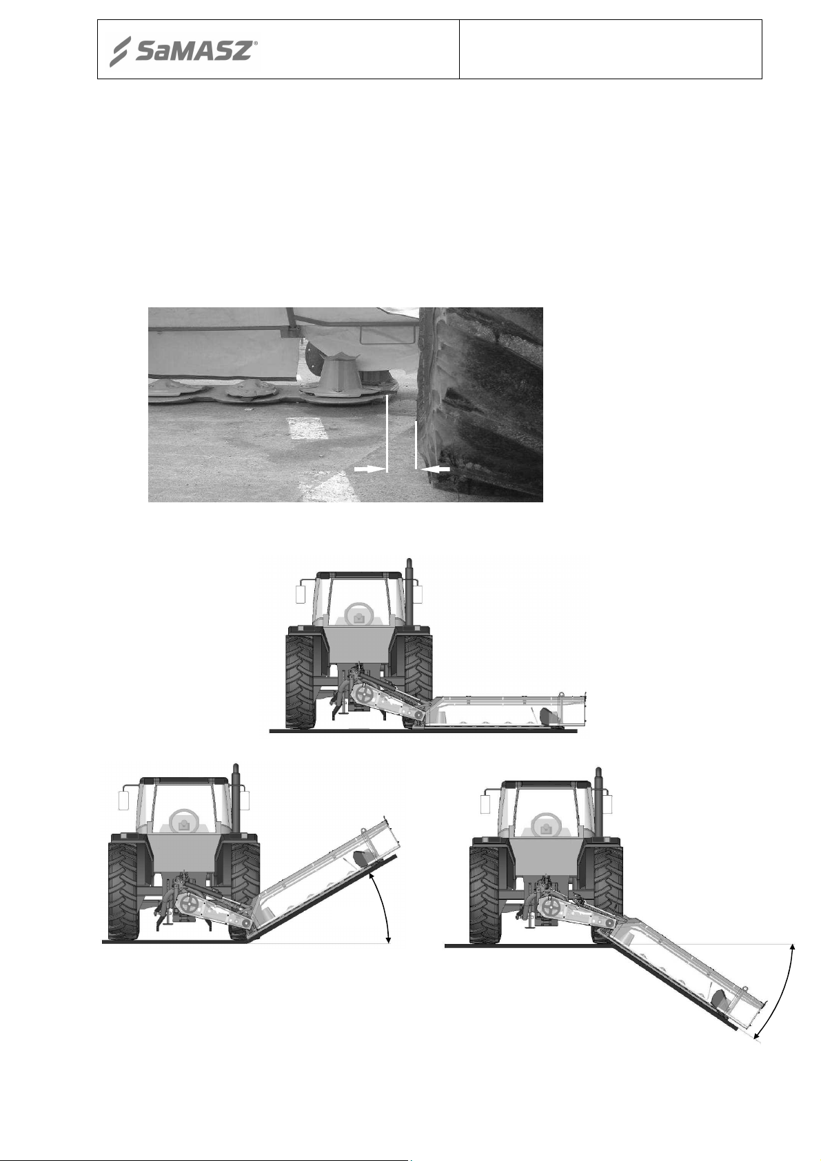
The proper distance between the end of cutterbar and tractor’s tyre Y should be about 0 to 4″ for
KDT 180, KDT 220, KDT 260. For KDT 300 Y should be between 11.8″ and 1′ 4. For KDT 340,
KDT 341 between 1′ 8″ and 1′ 12″.
For KDT 180; KDT 220;
KDT 260
Y = from 0 to 4″
For KDT 300
Y = from 11.8″ to 1′ 4″
For KDT 340;
KDT 341
Y = from 1′ 8″ to 1′ 12″
Y
Fig. 13. Proper distance between the cutterbar and tyre
5.5.1. Operating positions of the mower
max. 30º
Fig. 14. Operating positions of the mower

- 22 -
Operator’s manual
Rear disc mowers
KDT
5.6. Preparing the mower for work
NOTICE:
Before sale SaMASZ protects the cylinders with special grease against
weather which may cause premature wear. Before operating the mower,
remove the exceess grease from the cylinders.
Put the mower into motion when the cutterbar is on the ground so that oil can fill the whole
cutterbar. When the mower is in working position, please do the following:
be sure cutterbar to the ground,
connect PTO shaft between tractor and mower,
by means of upper regulating bar of the mower, adjust the cutterbar’s height and inclination
towards the ground. Proper inclination of the cutterbar is between 0° and 5°. It is regulated by
extending or shortening the bar,
slowly engage the PTO clutch and wait until the cutting unit reaches its rated speed. Tractor’s
engine rpm should be considerably lower, so that the fuel consumption could be reduced,
engage tractor gear and drive slowly into the grass-field. Flat meadows can be mowed with any
speed. If the meadow in uneven, reduce speed.
WARNING:
Do not operate the conveyor when it is in vertical position.
NOTICE:
DO NOT pull the cutterbar towards the tractor, because it will lead to
cutterbar’s premature wear or even its damage.
WARNING:
Improperly relieved cutting unit of the mower will cause increase of cutterbar
pressure on the ground which will lead to faster wear of sliding skids, overload
of cutterbar, higher fuel consumption, damage to the stubble and
5.7. Operation (mowing)
contamination of the fodder.
WARNING:
The operator must be seated in the tractor’s driver’s seat when the machine is
operating since only from that position is he able safely and properly operate
the mower. Before he leaves the driver’s seat, the operator must stop the
engine, apply the parking brake and turn off the tractor engine.
Always use appropriate protective equipment (safety footwear, gloves, ear protection and dust
mask)
Before using the machine, make sure that all the safety devices are in their correct positions and in a
good condition. These safety devices must be immediately replaced if they are faulty or damaged.
In particular, the protective cover must be checked regularly. It must be immediately replaced if it is
missing or damaged in any way.
IMPORTANT: If a disc mower is your first experience (you have mowed with 2-drum mower),
you need a piece of essential information:
1. Main advantage of disc mowers is their small power demand – 20% less tractor power, small
moment of inertia and possibility to manufacture mowers with large working width.

- 23 -
Operator’s manual
Rear disc mowers
KDT
2. There is however a certain disadvantage - creased stubble, especially when it comes to lying
grass. Straight grass may be mowed with horizontal adjustment of the mower and then the
stubble will be even, but it will not look as attractive as with 2-drum or 4-drum mowers,
because the knives work horizontally to the ground and inclined grass bends because of wind
blasts. After the grass is mowed, it stands up, which makes an impression of inaccurate mowing.
Every mower may leave stripes of uncut grass when it comes to the knives which cut the grass
towards the grass direction.
It is a normal phenomenon. Practically, it is not possible to achieve such attractive stubble as in
2-drum mowers, because the knives work horizontally or at an angle of up to 8° to the ground,
and when it comes to 2-drum and 4-drum mowers, slantwise through the ground (even 23°).
Despite these ‘disadvantages’, disc mowers are ‘winning farmers’ trust’ and modern
technologies give an opportunity to manufacture very durable mowers.
3. The most even stubble with very low grasses is obtained with disc mowers when half of
the discs rotate to the right and half to the left. A disadvantage of this system is a narrow and
thick windrow which needs to be spread out.
5.7.1. Essential information concerning mowing
Optimum work parameters
1. Inclination towards the front 0-5 degrees which equates to 1.8" - 2.8" of mowing height.
2. Operation speed around 6 mph or more, if the conditions allow.
3. PTO rpm = 470-520 rpm. PTO rpm less than 540 may cause stripes of uncut grass between the
disc.
High and inclined grass
1. Heighten the cutterbar’s inclination to H = about 1.8".
2. If there is no inclination the grass will be wedged on the forming drums.
3. Speed can be more than 8 mph (the faster – the better).
4. Do not turn in the mowed grass.
Optimum inclination of the cutterbar towards the ground is between 0° to 5°. If the inclination
exceeds 5°, there might be a slight unevenness of mowed grass. It impairs slightly the quality of
mowing and has an influence on the mower’s operation. When the cutterbar is pulled in the other
direction, it significantly impairs the quality of mowing and in some cases the mower stops
mowing. Besides, it may lead to premature wear or even damage of the slides and cutterbar.
When high grass prevails, first and second cut should be mowed at height level 2.4" - 2.8", but
when the grass grows low it should be mowed at 2". The last cut should be mowed a little bit
higher, 2.8" - 3" above the ground.
Too high a PTO rpm whirls the air, which may cause inclination of the grass in front of discs,
which impairs the quality of mowing.
Too low a PTO rpm impairs the quality of mowing and in some cases the mower stops mowing
(too low linear velocity of the knife).
In contrast with 2-drum mowers, straight mounting of the mower and full speed are not always
possible. Adjust inclination of the mower, PTO rpm, speed and correctness of knife-mounting to
get the best results.
In case of mowing soft meadows, the pressure of the cutterbar on the ground should be reduced
by adjusting support springs.
Always check to make sure that the ground speed suits the conditions or work and that it does
not create a potential source of danger
Do not take sharp turns anytime and do not operate in reverse.

- 24 -
device operates
R
Operator’s manual
Fig. 15. Shape of the stubble with cutterbar’s inclination 0°, 3° and 5°
5.7.2. Design and and operation of safety breakaway device
Rear disc mowers
KDT
In the event of hitting an immovable obstacle one of the safety device flat bars slides out and
disconnects the safety device. After that the mower folds back about 34 degrees (Fig. 17).
The operator has time to shut off the tractor and protect the mower. Safety device spring is
adjustable (Fig. 16), therefore changing the force needed to make safety device work.
Fig. 16. Safety device
Fig. 17. The mower breaks back when the safety

- 25 -
take turns
to take turns
Operator’s manual
Rear disc mowers
KDT
Recommended length of safety device spring R (Fig. 16) should be 5.6". If the safety device breaks
away too easily, tighten up the spring approximately .04"-.08". DO NOT tighten up too much,
because you may prevent the safety device from working and damage the mower.
5.7.3. Mower clogging
When operating the mower, pay attention to variable conditions on the field, which may cause the
mower to clog, such as: terrain unevenness, height and density of grass as well as other objects in
the grass. In order to avoid clogging, mowing speed should be adjusted to the conditions. In order to
take care of machine clogging, lower the cutterbar onto the ground, disconnect the drive and
remove the ignition key. When eliminating the mower's clogging wear all appropriate protective
gear.
5.7.4. Taking turns over swaths
Lift the mower with hydraulic cylinder and take the turn. The mower does not need to be
additionaly lifted by tractor’s 3-point linkage.
Fig. 18a. KDF & KDT mower set prepared to
Fig. 18b. KDF & KDT mower set prepared
5.8. Storing
Mower should be stored in paved, dry places, protected against precipitation. In order to
minimize the space necessary for storage the mower may be stored in a vertical position but always
on paved surface. Storing the mower on an unpaved surface may cause the mower to lose stability
and turnover.
NOTICE:
When stored for long time (e.g. in winter season), the machine should be in an
upright position on paved surface (with closed cylinders). Storing the mowe in a
horizontal position may cause faster wearing (rusting) of the cylinder from the inside
(through vent valve) by being penetrated by moisture from the air.
5.9. Dismounting mower from tractor
WARNING:
When dismounting, make sure there is no person in between the mower and
the tractor.
To dismount the mower from the tractor:
turn cutterbar's drive off,
place the mower on even, paved ground, lower and protect support legs, check, if the mower is
properly protected against falling,
turn the tractor's engine off and take ignition key off,
dismount tractor's rpm and place it on a PTO shaft holder, that is standard-delivered with the
mower,
disconnect hydraulic hose,
detach tractor's upper link and lower strands from mower's linkage.

- 26 -
Operator’s manual
Rear disc mowers
KDT
6. MOUNTING AND ADJUSTMENTS
6.1. Mounting and timing of the knives
The knives should be mounted as shown in
manufacturer recommended knives are measured 105x49x4 and conform to standard PN-EN
795:2002. Mount the knives so that cutting edges are directed towards ground, so that a knife lifts
the grass after cutting.
Fig. 19. Mounting of the knives on mowing discs
WARNING:
- Use only knives recommended by manufacturer.
- Check condition of knives and holders before each operation. Worn or
damaged knives should be replaced immediately.
6.2. Replacing the knives
Replace knives, if necessary, only in sets. Make sure all knives in a set are of the same length
and weight. The knife holders (Fig. 30) must not be damaged or deformed. If the knife holder pin is
worn too much, please replace it immediately.
NOTICE:
During work, if mower begins to shake, it means that the disc (discs) are
operating only with one knife. In that case, using the mower in this
condition for a long time could cause serious damage to the cutterbar.
WARNING:
When replacing knives, the engine must be stopped and the cutterbar must
lie on the ground. PTO shaft must be disconnected. Discs should be
perpendicular to cutterbar.
Fig. 20. Quick replacing of the knives with mounting lever
Fig.
19 and Fig. 20. The knives recommended by the

- 27 -
Operator’s manual
6.3. Adjusting the cutterbar
Rear disc mowers
KDT
Swath width is adjusted with swath guides mounted on the 3-point linkage frame of
the cutterbar (Fig. 21).
In order to adjust the guide, the following should be performed (for: KDT 180, KDT 220,
KDT 260, KDT 300, KDT 340):
loosen locknuts (2) and screws (3),
shift the guide arm (6),
tighten screws (3) and locknuts (2),
loosen locknuts (4) and screws (5),
then adjust height and shield angle (7),
tighten screws (5) and locknuts (4).
1
3 2
6
5
4
7
Fig. 21. Adjustment of swath guides: 1 - swath guide, 2 - locknuts, 3- arm adjustment screws, 4 - locknuts, 5-
shield adjustment screws, 6- guide arm, 7- shield
In order to set swath width, adjustment of swath guides (1) should be performed (Fig. 22)
(for: KDT 220 S, KDT 260 S, KDT 260 SL):
loosen eye screw (2) of the swath guide,
set the swath guide (1) as needed,
tighten screw (2),
even spreading of swath might be adjusted with wheels (3) the same as it is preformed with
guides.

- 28 -
Operator’s manual
Rear disc mowers
KDT
1
2
1
Fig. 22. Adjustment of swath guides: 1- swath guide, 2 - adjustment screw, 3 - swath wheel
In order to set swath width, adjustment of swath guides (1) should be performed (Fig. 23)
(for: KDT 220 W, KDT 260 W):
loosen eye screw (2) of the swath guide,
set the swath guide (1) as needed,
tighten screw (2).
1
2
1
Fig. 23. Adjustment of swath guides: 1- swath guide, 2 - adjustment screw
NOTICE:
Before you change the knife check disc turns (Fig. 24).
CAUTION:
Different mounting of the knives will block the mower. When mounting pay
particular attention to loose rotation of the knife on the knife holder pin.

- 29 -
Operator’s manual
Rear disc mowers
KDT
NOTICE:
Due to high discs rpm speed, change knife holders in sets of the same weight
– each holder has weight marked. Improperly changed knife holders will
damage disc bearings.
KDT 180 KDT 220
KDT 260 KDT 300
KDT 340
KDT 341
Fig. 24. Rotation directions of disks
6.4. Adjusting the cutting height
By means of upper link S (Fig. 8) adjust the cutting height.
Extending the link S increases the cutting height and shortening the link
reduces it. Cutting height is shown by the scale placed on the 3-point
linkage frame (Fig. 25), recommended height is 1.8"÷2.8".
Fig. 25. Cutting height scale
Disc with the
forming drum
Disc without
the forming drum

- 30 -
~1'4"
Operator’s manual
6.5. 3-point linkage support chain
a)
Support chain is used to ensure 3-point linkage frame of the mower is always at the same
height, to set the mowing unit parallel to the ground and to relieve the hydraulic lift of the tractor.
When connecting mower to the tractor, the hanger plate A of support chain should be disconnected
from chain and put on the pin B of upper link (Fig. 26a). Then the mower has to be lifted with
hydraulic lift about 1'4" high (Fig. 26b). The support chain is then connected to the hanger plate A,
so that is tensioned when the mower is in its working position. If the 3-point linkage frame is more
than 1'4" above the ground, adjust the chain.
6.6. Adjusting the space between tine conditioner’s mask and its shaft
(Models: KDT 220 S and KDT 260 S(SL))
Depending on size and thickness of the mowing grass, there may be a necessity to adjust
the mask of the conditioner. The higher and thicker grass, the bigger the space between
conditioner’s mask and its shaft should be. Proper adjustment should be based on the experience, in
order not to block the conditioner and not to activate the friction clutch of PTO shaft. The way how
the mask is regulated is shown in Fig. 27.
Fig. 27. Adjusting tine conditioner’s mask
B
A
b)
Fig. 26. Support chain
+
Rear disc mowers
KDT
-

- 31 -
Operator’s manual
Rear disc mowers
KDT
6.7. Replacing the conditioner’s tines
(Models: KDT 220 S and KDT 260 S(SL))
Prior to commencing any operation, check condition of bolts on which flails are set, as well as
condition of fails themselves. If flails or bolts are worn or damaed, it is necessary to replace them.
Bear in mind, that flails should be replaced in pairs (opposite) featuring the same weight
in order to keep shaft well balanced. Not keeping the shaft well balanced may lead to premature
wearing of bearings as well as the shaft itself.
Replacement of flails 3 consists in unscrewing of nuts 2, removing bolts 4 and mounting
brand new flails 3 (Fig. 28).
NOTICE:
In order to tighten screw connection use special purpose bolt M16×60 z.
Property Class 10.9 and self-protected nut M16 z. Property Class 8.8; torque
down until tight.
1. Scarfier shaft
2. Self-locking nut M16 z. Property Class 8.8
3. Flail
4. Bolt M16x60 kl. 10.9
1. Scarfier shaft
2. Self-locking nut M16 z. Property Class 8.8
3. Washer
4. Plastic flail
5. Bolt M16x60 kl. 10.9
6. Plastic flail insert
Fig. 28b. Replacement of flails in light-weight conditioner roller
Fig. 28a. Parts of tine conditioner
1
2
3
6
5
4

- 32 -
Operator’s manual
Rear disc mowers
KDT
Tab. 5. Torque values for bolts
In the absence of specific torque values, the following chart can be used as a guide to the
maximum safe torque for a particular size and grade of fastener. There is no torque difference for
fine or coarse threads. Torque values are based on clean, dry threads. Reduce value by 10% if
threads are oiled before assembly.
6.8. Adjusting force of the prssure of roller conditioner
(Models: KDT 220 W and KDT 260 W)
If need be, the force of the roller conditioner’s pressure can be regulated by changing
the tension of springs S (Fig. 29) by means of the nut N. Adjustment should be done on both sides
of the conditioner
N
S
Fig. 29. Adjusting the force of the pressure of roller conditioner
6.9. Maintenance and service
6.9.1. Checking the knives and knife holders
All knives should have the same lengths and weights. Always check mower before starting
work for damaged, missing and/or worn knives. Replace them, if necessary, only in sets.
If the knife holder pin is worn too much and/or the knife holder is worn or deformed, please
replace it immediately (Fig. 30).

- 33 -
b)
Operator’s manual
Rear disc mowers
KDT
a)
10min.
Fig. 30. Permissible wear of knife holder pin on disk a) knife base M12 b) knife base M12 with claw
NOTICE:
If the knife is missing or disc cover plate is damaged the vibrations may
occur, which leads to cutterbar’s damage. In that case warranty claim will be
revoked. If the disc or disc cover plate is damaged, the whole set must be
immediately replaced (2 knives) with new genuine ones.
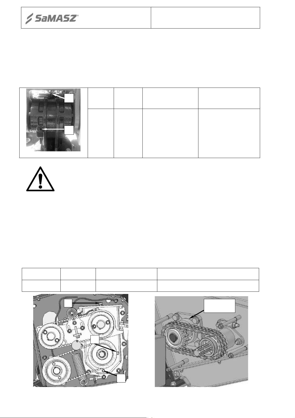
6.9.2. Checking the tension of the V-belts
Check the V-belt tension. V-belts are tensioned with spring tensioner (Fig. 31) equipped with
checking plate. Distance S between plate tip and holder should be 0.4". If the gap is wider the
V-belts will be looser. Tensioning is done by nuts N. When any of the belts are damaged,
the complete set must be replaced.
S
Fig. 31. Spring V-belts tensioner
6.9.3. Inspection of tension of toothed belt for gears of rollers and conditioner
Drive from cog gear shaft is transmitted on rollers/conditioner roller axles through toothed
belts. Constant belt tension is provided by tensioner adjustable with tensioning nut N (Fig. 32b)
Belt tightening can be checked through eye O (Fig. 32a and c). In order to tension the belt
remove safety guard (Fig. 32a and c) having unscrewed four nuts S. Then, tension the toothed belt
using tensioning screw and nut N (Fig. 32b and d). Properly tensioned belt, when pressed with
thumb in the middle should deflect by approx.. 0.2".
N

- 34 -
O
Operator’s manual
Fig. 32a. Rollers transmission guard
Fig. 32c. Conditioner roller transmission
6.9.4. Daily maintenance
S
guard
Rear disc mowers
KDT
N
Fig. 32b. Adjusting tension of transmission
toothed belt
Fig. 32d. Adjusting tension of toothed belt for
conditioner roller transmission
When you finish each day of operation carry out the following maintenance:
check all visible parts and components and their connections; tighten all loose bolts and nuts
and replace all damaged and/or worn parts with new genuine ones,
clean the mower, especially between discs and cutterbar, because grass with mud may damage
bearings in disc module,
remove grass and mud,
check the cutterbar,
grease PTO shaft tubes with STP grease,
if necessary, lubricate the parts and components according to lubrication instructions (chapter7).
Parts which may cause risk to operator’s health and safety are as follows: damaged discs, missing or
damaged safety covers, worn or damaged hydraulic hoses, PTO shaft guides, worn knives and knife
holder pins.
6.9.5. After-season maintenance and storing of machine
At the end of mowing season the following shall be performed:
lower the mower’s cutterbar onto the ground,
take the PTO shaft extension out of the tractor rpm or dismount the complete PTO shaft and
install it into corresponding holder at the 3-point linkage frame,
unmount hydraulic and electrical hoses from the tractor and hang them onto corresponding
holders on the 3-point linkage frame,

- 35 -
Operator’s manual
unmount the mower from the tractor (reverse procedure as in case of attaching the mower to
Rear disc mowers
KDT
the tractor item 5.1), and then drive the tractor away.
Mower should be stored in standstill position, so it is supported onto supporting leg and the
cutterbar. It is recommended to store the set on paved ground, preferably in roofed places,
inaccessible to unauthorized personnel or animals.
If the machine is stored for a long period of time before first operation, its technical condition
should be examined and special attention should be paid to the hydraulics and the drive. Paint the
area where the paint is missing, hydraulic hoses checked and lubricated.
Additionally:
remove any traces of rust and paint the area,
check the oil level in the angle drives and the cutterbar (Section 7). If leaks are discovered, they
should be repaired immediately and lost oil replaced. If water in oil is discovered, immediately
change the oil as it could cause corrosion of internal mechanisms such as gear wheels, bearings,
or shafts, and cause breakdowns,
periodically inspect the mower and lubricate moving parts in order to protect them from
corrosion which adversely affects the proper operation of the mower,
check hydraulic hoses regularly. Replace any damaged or old hoses. In any case, you should
replace hoses that have been in use more than 5 years from the date of their manufacture printed
on the hose.
7. LUBRICATION
7.1. Cutterbar
Refilling the oil of the cutterbar is done through the inlet A (Fig. 33). Proper oil level is 0.2" -
0.3" from the cutterbar bottom. Oil capacities are given in table below.
Tab. 6. Oil capacities
Model Oil capacity [l] Oil type Lubrication frequency
KDT 180 – 5' 11" 3.5
KDT 220 S/W – 7' 3" 4.5
KDT 260 S,SL/W – 8' 6" 5.0
KDT 300 – 9' 10" 6.0
KDT 340 – 11' 2"
KDT 341 – 11' 2"
6.5
80W90
(if working intensively more frequently)
Once every 3 seasons
A
Fig. 33. Point of oil inspection a) and manner of oil replacement in cutterbar b)
b)
In order to drain oil out of the cutterbar, firstly lift the mower up onto tractor's links and then
dismount the cutterbar closure as shown on Fig. 33b and tilt the cutterbar so, as to enable the old oil
to drain. Oil drained out of the cutterbar should be disposed in a proper manner.
- 36 -
[
US gal lqd
]
(if working intensively)
C
A
B
Operator’s manual
Rear disc mowers
KDT
7.2. Intersecting axis gear
Everyday before starting work please check the oil level and, if needed, please refill after
having removed the vent A on the top of the gear (Fig. 34). The oil level can be checked through
the check opening B on the side of the gear. Please refill the oil until it is visible in the check
opening B. The oil capacity: about 0.26 US gal lqd.
Tab. 7. Oil capacities
Oil
Model
Capacity
[US gal lqd]
Oil type Lubrication frequency
All types
0.26
Transol 680 ÷ 1000
(acc. to ISO 3448 oil
viscosity grade :
VG-680 – 1000 )
Once every 3 seasons
(if working intensively
more frequently)
Fig. 34
IMPORTANT:
The above instructions should be strictly followed. If the discs in
the cutterbar rotate loosely, do not worry about the high intersecting axis
gear temperature; after long working time it may reach even 100oC.
7.3. Roller conditioner’s gearbox
Before you check the lubrication of the gearbox, please remove the safety guard. Everyday
before starting work please check the oil level and, if needed, please refill after having removed
the vent A on the top of the gearbox (Fig. 35) The oil level can be checked through the check
opening B on the side of the gear. Please refill the oil until it is visible in the check opening B.
The oil level: about 0.13 US gal lqd. Check oil level when the cutterbar is on the ground. Removing
the worked oil from the gearbox is done through the outlet C.
Tab. 8. Oil capacities
Model
Oil capacity
Oil type – for gearboxes Lubrication frequency
All models 0.13 80W90
Fig. 35. Roller conditioner’s gearbox
A
B
lubrication points
Once every 3 seasons
Lubrication
point
Fig. 36. Bearing lubrication
point with LT43 grease
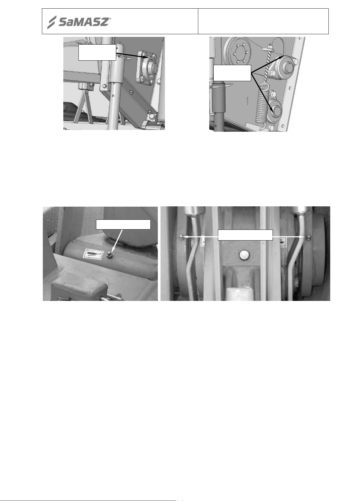
- 37 -
with LT43 grease
with
LT43 grease
s
uspension with STP grease
with STP grease
Operator’s manual
Lubrication
point
Rear disc mowers
KDT
Lubrication
points
Fig. 37. Bearing lubrication point
Fig. 38. Bearing lubrication point
7.4. Bearings and joints
Every 50 mower working hours lubricate tine/roller conditioner’s bearings (Fig. 36, Fig. 37,
Fig. 38) with LT43 grease (or other designed to lubricate rolling and slide bearings, that work in -
30oC do+130oC) and main joints of the mower (Fig. 39, Fig. 40) with STP grease.
Lubrication point
Lubrication point
Fig. 39. Lubrication point of the
Fig. 40. Lubrication point of the suspension

- 38 -
1 Lack of knives
Put on
knives
2 Worn knives
Replace knives
(left
– right)
instructions
instructions
(The most frequent mistake
)
6 Too low work speed
Speed up to V
≥10 km/h
spring tension acc. to instructions
Worn V
-
belts
– Replace V
-
belts
8 Damaged tractor’s PTO
Repair
aroun
d 380 rpm
1200 rpm
very small grass or after the rain
4 cm
Too low work speed
Speed up to 10 km/h or more
maximum
instructions
Worn elements of safety device
Replace the safety device
transmitted from the tractor
Damaged bearings in the disc hub
SaMASZ service
and check valve
connector and check valve
Tractor’s hydraulic system is damaged
Check tractor’s hydraulic system
and replace damaged sealings
work
and if need be replace
Operator’s manual
8. MALFUNCTION AND THEIR REPAIRS
Tab. 9. Defects and their repair
Defect Reason Repair
Rear disc mowers
KDT
Mower stops working
(partly)– leaves stripes of
uncut grass between the discs
The grass is wound on the
forming drums
Grass blocks the mower –
lack of grass flow or the flow
is uneven
Safety device is working
often incorectlly without
clear reason
Mower does not work, even
though the drive is
3
4
5
7
9
Mower with either tine or roller conditioner may mow improperly in case of
Mowing lying grass without inclination
Improperly mounted knives
Improper front inclination
Too high PTO rpm
Slidind V-belts
Check tractor’s PTO if it has 540 E.
E stands for economical rpm –
towards the front
Swath guides are set too narrow
Insufficient spring tension
Torn off shaft of intersecting axis gear
Put on knives strictly acc. to
Adjust inclination strictly acc. to
Reduce PTO rpm
Too low spring tension – regulate
In that case operate with 1000 PTO
rpm but low tractor’s rpm – around
Always mow low and fast –
inclination towards the front –
Widen swath guides to the
Adjust spring tension acc. to
Replace intersecting axis gear
023.01.COER
Mower is blocked
Mower’s hydraulics does not
work
Leaking cylinder Dirty oil in hydraulic unit of the tractor
Excesive vibration during
Oil leak in gear Not tight assembly
Damaged gears in the cutterbar.
Damaged or dirty hydraulic cylinder
Damaged PTO shaft
This repair must be done by
Replace or clean hydraulic
Replace oil in hydraulic unit of the
tractor (recommended class of
cleanliness of oil according to
NAS 1638 is minimum 9-10).
Purchase repair kit of the cylinder
Check the condition of PTO shaft
Examine tightness and check oil
level.

- 39 -
Operator’s manual
Rear disc mowers
KDT
9. DISASSEMBLY AND WITHDRAWAL FROM USE
9.1. Scrapping
If the mower cannot be repaired anymore, it should be withdrawn from use
.
To do so, oil from intersecting axis gear and cutterbar should be drained and delivered to a
proper waste treatment company. Clean the mower parts, dismantle and dispose properly of all
plastic parts. After that, the mower can be scrapped.
10. WARRANTY CARD
REAR DISC MOWER
Serial number
Date of manufacture
Manufacturer’s stamp
QC signature
Date of purchase
Dealer’s stamp
Dealer’s signature
The product quality has been checked and meets the required standards and regulations and is
permitted for use.
NOTE:
A warranty card without the required information or with corrected or illegible
information – is invalid.
11. WARRANTY TERMS
11.1. Warranty claims procedures
1. The manufacturer guarantees its products against faults in materials or production.
2. The warranty period is for two years from the date of sale to the purchaser, stated above.
3. Any repair which is subject to warranty should be carried out by an authorised SaMASZ dealer.
Upon completion of the repair the dealer must submit a warranty claim within 14 days.
4. Warranty claims regarding replacing of the product or repayment are considered within 14 days
by the manufacturer.
5. The following cases are not covered by warranty:
a) wearing parts: mowing discs, sliding skids, sidle bushings Pcw, intersecting axis gears
and parts inside the gearboxes, bushings and sliding elements, joints, knife holders,
cutting knives, V-belts, chain gears, drivechain, conditioner’s tines and rollers, roller
conditioner’s rubbers, bearings, rubber-metal fenders, safety curtains, conveyor’s
belts, swath guides rubbers, connective elements, etc.
These repairs may be done only at purchaser’s cost.
b) use for any other purpose than those described in the operator’s manual,
c) operation on stoney fields and results such as: damage of tine conditioner's shaft, discs,
bending of cutterbar (stone with its diameter of 5.5" will not move between the discs
and conditioner's shaft,
d) running into any obstacle,
e) too fast lowering of the cutterbar to the ground,

- 40 -
Operator’s manual
Rear disc mowers
KDT
f) transport and accidental damage,
g) breaking, damage of tine conditioner's shaft, conveyor's belt.
6. The Purchaser bears the costs of technical evaluation - when the manufacturer finds that
a claimed product is free of defects and a technical report confirms that.
7. The manufacturer has the right to cancel a warranty in the following cases:
a) interference of the interior of the mower, changes of its mechanical design or
intentional damages, bending parts of the mower and so on.
b) operating with only 1 knife on the disc or without disc cover plates.
c) damage caused by accidents, running into obstacles or other events, for which
the warrantor is not responsible,
d) using of knives, knife holders and mountings other than originally delivered by
SaMASZ,
e) negligent maintenance,
f) use of non-genuine spare or replacement parts that are not specifically designed for
the model in question,
g) lack of needed records in the warranty card or filling in the warranty card
independently,
h) use of the mower not in accordance with operator’s manual or for incorrect purpose,
or use of the machine by untrained persons.
8. Manufacturer can break the service agreement with immediate effect when the user does not pay
the invoice according to that agreement in a timely manner and the delay in payment is longer
than 30 days from maturity date. Breaking the service agreement caused by the user also
invalidates the warranty.
NOTE:
Please ask your dealer to complete and return the warranty card, otherwise you may lose
your warranty rights.
The warranty card is valid only when it contains the following information: address, date
and place of purchase, mower type and invoice number.
11.2. Warranty repairs record
Repairs description and changed spare parts
Date, stamp and signature of repair shop
:
.
Date, stamp and signature of repair shop.
Date, stamp and signature of repair shop
.

- 41 -
1
3
1
3
1
3
2 3
2 3
2 3
1
3
3 1
2
1
2
3
MT
C
Operator’s manual
Rear disc mowers
KDT
APPENDIX
CALCULATING AXIS LOAD
ATTENTION!
When mounting the machine on a tractor using front and/or rear 3-point
linkage, a maximum value of permissible load cannot be exceeded – tractor's
front axis load must be 20% of the tractor's overall weight.
Before using the tractor-machine assembly, check whether these conditions
are met, while calculating and weighing the assembly.
1. Defining the total weight, axis load, tyre load capacity and minimum load.
M
P
T
P
A
For calculations the following data is necessary:
T [lbs.] Tractor's overall weight
TP [lbs.] Front axis load on unloaded tractor
TT [lbs.] Rear axis load on unloaded tractor
MP [lbs.]
Total weight of machine mounted on front 3-point linkage or weight of
front ballast
B
T
T
D
MT [lbs.]
A [ft.]
B [ft.] Distance between tractor's axes
C [ft.]
D [ft.]
Total weight of machine mounted on rear 3-point linkage or weight of rear
ballast
Distance between centre of gravity of machine mounted on front 3-point
linkage / front ballast and tractor's front axis centre
Distance between tractor's rear axis centre and centres of ball joints on
tractor's lower links
Distance between centres of ball joints on tractor's lower links and centre of
gravity of machine mounted on rear 3-point linkage / rear ballast
Refer to tractor's operation manual
Refer to technical data for machine in operation manual or price list
Dimensions / measurement

- 42 -
Operator’s manual
Calculating minimum weight of front ballast M
Rear disc mowers
KDT
– machine mounted at tractor's rear or
P min.
at rear and front:
Calculating minimum weight of rear ballast M
– machine mounted at tractor's front:
T min.
Calculating real axis load at tractor's front axis T
* If machine is mounted on tractor's front 3-point linkage (MP) it is lighter than minimum required load at the front, so
increase the weight of this machine to the required minimum load
Calculating total weight of tractor-machine assembly MC:
* If machine is mounted on tractor's rear 3-point linkage (MT) it is lighter than minimum required load at the rear, so
increase the weight of this machine to the required minimum load
Calculating real axis load at tractor's rear axis T
Tyre load capacity – apply double the load indicated by the tyres' manufacturer.
T rzecz.
ENTER THE ABOVE CALCULATION DATA AND TECHNICAL DATA PROVIDED BY
THE MANUFACTURER IN THE BELOW TABLE.
Real value from
calculations
Value to
technical
specification
Minimum weight of
front or rear ballast
M
Pmin.
or M
Tmin.
Total weight
MC
≤
Front axis load
T
P rzecz
.
≤
Rear axis load
T
T rzecz.
≤
Minimum ballast must be reached by mounting the machine or additional weights provided on the tractor.
Values resulting from calculations should be lower than or even to values given in technical specification.
P rzecz
:
.
:
Double value of
tyre capacity
load
≤
≤
 Loading...