

Page 1

www.s-a-m.com
User Manual
IQFDA31
Dual Channel 3G/HD/SD-SDI Re-clocking Distribution Amplifier with
Fiber I/O
Page 2

IQFDA31 Information and Notices
Issue 1 Rev 1 Page 2 © 2016 SAM
Information and Notices
Copyright and Disclaimer
Copyright protection claimed includes all forms and matters of copyrightable materia l and
information now allowed by statutory or judicial law or hereinafter granted, including without
limitation, material generated from the software programs which are displayed on the screen
such as icons, screen display looks etc.
Information in this manual and software are subject to change without notice and does not
represent a commitment on the part of SAM. The software described in this manual is
furnished under a license agreement and can not be reproduced or copied in any manner
without prior agreement with SAM or their authorized agents.
Reproduction or disassembly of embedded computer programs or algorithms prohibited.
No part of this publication can be transmitted or reproduced in any form or by any means,
electronic or mechanical, including photocopy, recording or any information storage and
retrieval system, without permission being granted, in writing, by the publishers or their
authorized agents.
SAM operates a policy of continuous improvement and development. SAM reserves th e ri ght
to make changes and improvements to any of the products described in this document
without prior notice.
Contact Details
Customer Support
For details of our Regional Customer Support Offices please visit the SAM website and
navigate to Support/24/7-Support.
www.s-a-m.com/support/247-support/
Customers with a support contract should call their personalize d number, which can b e found
in their contract, and be ready to provide their contract number and details.
Page 3

IQFDA31 Contents
Issue 1 Rev 1 Page 3 © 2016 SAM
Contents
Information and Notices . . . . . . . . . . . . . . . . . . . . . . . . . . . . . . . . . . . . . . . . . . . . . . . . 2
1 Introduction . . . . . . . . . . . . . . . . . . . . . . . . . . . . . . . . . . . . . . . . . . . . . . . . . . . . . . . . . 4
1.1 Description . . . . . . . . . . . . . . . . . . . . . . . . . . . . . . . . . . . . . . . . . . . . . . . . . . . . . . 4
1.2 Block Diagram. . . . . . . . . . . . . . . . . . . . . . . . . . . . . . . . . . . . . . . . . . . . . . . . . . . . 4
1.3 Feature Summary . . . . . . . . . . . . . . . . . . . . . . . . . . . . . . . . . . . . . . . . . . . . . . . . . 5
1.4 Order Codes . . . . . . . . . . . . . . . . . . . . . . . . . . . . . . . . . . . . . . . . . . . . . . . . . . . . . 5
1.5 Rear Panel View . . . . . . . . . . . . . . . . . . . . . . . . . . . . . . . . . . . . . . . . . . . . . . . . . . 5
1.6 Enclosures. . . . . . . . . . . . . . . . . . . . . . . . . . . . . . . . . . . . . . . . . . . . . . . . . . . . . . . 6
1.6.1 B-style Enclosure . . . . . . . . . . . . . . . . . . . . . . . . . . . . . . . . . . . . . . . . . . . . . 6
1.6.2 A-style Enclosures. . . . . . . . . . . . . . . . . . . . . . . . . . . . . . . . . . . . . . . . . . . . . 6
2 Technical Specification. . . . . . . . . . . . . . . . . . . . . . . . . . . . . . . . . . . . . . . . . . . . . . . . 7
3 Connections. . . . . . . . . . . . . . . . . . . . . . . . . . . . . . . . . . . . . . . . . . . . . . . . . . . . . . . . 10
3.1 SDI Input . . . . . . . . . . . . . . . . . . . . . . . . . . . . . . . . . . . . . . . . . . . . . . . . . . . . . . . 10
3.2 SDI Outputs. . . . . . . . . . . . . . . . . . . . . . . . . . . . . . . . . . . . . . . . . . . . . . . . . . . . . 10
3.3 SFP . . . . . . . . . . . . . . . . . . . . . . . . . . . . . . . . . . . . . . . . . . . . . . . . . . . . . . . . . . . 10
4 Card Edge LEDs . . . . . . . . . . . . . . . . . . . . . . . . . . . . . . . . . . . . . . . . . . . . . . . . . . . . 11
5 Operation Using the RollCall Control Panel . . . . . . . . . . . . . . . . . . . . . . . . . . . . . . 12
5.1 Information Window. . . . . . . . . . . . . . . . . . . . . . . . . . . . . . . . . . . . . . . . . . . . . . . 12
5.1.1 Unit Status. . . . . . . . . . . . . . . . . . . . . . . . . . . . . . . . . . . . . . . . . . . . . . . . . . 12
5.1.2 SFP Status . . . . . . . . . . . . . . . . . . . . . . . . . . . . . . . . . . . . . . . . . . . . . . . . . 12
5.2 Input . . . . . . . . . . . . . . . . . . . . . . . . . . . . . . . . . . . . . . . . . . . . . . . . . . . . . . . . . . 13
5.2.1 Input 1 and 2 . . . . . . . . . . . . . . . . . . . . . . . . . . . . . . . . . . . . . . . . . . . . . . . . 13
5.2.2 Outputs . . . . . . . . . . . . . . . . . . . . . . . . . . . . . . . . . . . . . . . . . . . . . . . . . . . . 13
5.3 SFP . . . . . . . . . . . . . . . . . . . . . . . . . . . . . . . . . . . . . . . . . . . . . . . . . . . . . . . . . . . 14
5.3.1 SFP Transmit . . . . . . . . . . . . . . . . . . . . . . . . . . . . . . . . . . . . . . . . . . . . . . . 14
5.3.2 SFP Receive . . . . . . . . . . . . . . . . . . . . . . . . . . . . . . . . . . . . . . . . . . . . . . . . 14
5.4 Memory 1-16. . . . . . . . . . . . . . . . . . . . . . . . . . . . . . . . . . . . . . . . . . . . . . . . . . . . 15
5.4.1 Recall Memory . . . . . . . . . . . . . . . . . . . . . . . . . . . . . . . . . . . . . . . . . . . . . . 15
5.4.2 Save Memory . . . . . . . . . . . . . . . . . . . . . . . . . . . . . . . . . . . . . . . . . . . . . . . 15
5.4.3 Last Recalled Memory. . . . . . . . . . . . . . . . . . . . . . . . . . . . . . . . . . . . . . . . . 15
5.4.4 Save Memory Name . . . . . . . . . . . . . . . . . . . . . . . . . . . . . . . . . . . . . . . . . . 16
5.5 Logging . . . . . . . . . . . . . . . . . . . . . . . . . . . . . . . . . . . . . . . . . . . . . . . . . . . . . . . . 17
5.5.1 Logging Misc. . . . . . . . . . . . . . . . . . . . . . . . . . . . . . . . . . . . . . . . . . . . . . . . 17
5.5.2 Logging Inputs. . . . . . . . . . . . . . . . . . . . . . . . . . . . . . . . . . . . . . . . . . . . . . . 17
5.5.3 Logging SFP . . . . . . . . . . . . . . . . . . . . . . . . . . . . . . . . . . . . . . . . . . . . . . . . 18
5.5.4 Log Field Descriptions. . . . . . . . . . . . . . . . . . . . . . . . . . . . . . . . . . . . . . . . . 19
5.6 RollTrack. . . . . . . . . . . . . . . . . . . . . . . . . . . . . . . . . . . . . . . . . . . . . . . . . . . . . . . 21
5.6.1 Disable All . . . . . . . . . . . . . . . . . . . . . . . . . . . . . . . . . . . . . . . . . . . . . . . . . . 21
5.6.2 Index . . . . . . . . . . . . . . . . . . . . . . . . . . . . . . . . . . . . . . . . . . . . . . . . . . . . . . 21
5.6.3 Source. . . . . . . . . . . . . . . . . . . . . . . . . . . . . . . . . . . . . . . . . . . . . . . . . . . . . 21
5.6.4 Address. . . . . . . . . . . . . . . . . . . . . . . . . . . . . . . . . . . . . . . . . . . . . . . . . . . . 22
5.6.5 Command . . . . . . . . . . . . . . . . . . . . . . . . . . . . . . . . . . . . . . . . . . . . . . . . . . 22
5.6.6 RollTrack Sending . . . . . . . . . . . . . . . . . . . . . . . . . . . . . . . . . . . . . . . . . . . 22
5.6.7 RollTrack Status . . . . . . . . . . . . . . . . . . . . . . . . . . . . . . . . . . . . . . . . . . . . . 22
5.7 Setup. . . . . . . . . . . . . . . . . . . . . . . . . . . . . . . . . . . . . . . . . . . . . . . . . . . . . . . . . . 23
5.7.1 Default Settings. . . . . . . . . . . . . . . . . . . . . . . . . . . . . . . . . . . . . . . . . . . . . . 23
5.7.2 Factory Defaults . . . . . . . . . . . . . . . . . . . . . . . . . . . . . . . . . . . . . . . . . . . . . 23
5.7.3 Restart. . . . . . . . . . . . . . . . . . . . . . . . . . . . . . . . . . . . . . . . . . . . . . . . . . . . . 23
5.7.4 Input Name . . . . . . . . . . . . . . . . . . . . . . . . . . . . . . . . . . . . . . . . . . . . . . . . . 23
5.8 SFP Setup. . . . . . . . . . . . . . . . . . . . . . . . . . . . . . . . . . . . . . . . . . . . . . . . . . . . . . 24
5.8.1 Restart. . . . . . . . . . . . . . . . . . . . . . . . . . . . . . . . . . . . . . . . . . . . . . . . . . . . . 24
5.8.2 Configure Type . . . . . . . . . . . . . . . . . . . . . . . . . . . . . . . . . . . . . . . . . . . . . . 24
Page 4
IQFDA31 Introduction
Issue 1 Rev 1 Page 4 © 2016 SAM
1 Introduction
1.1 Description
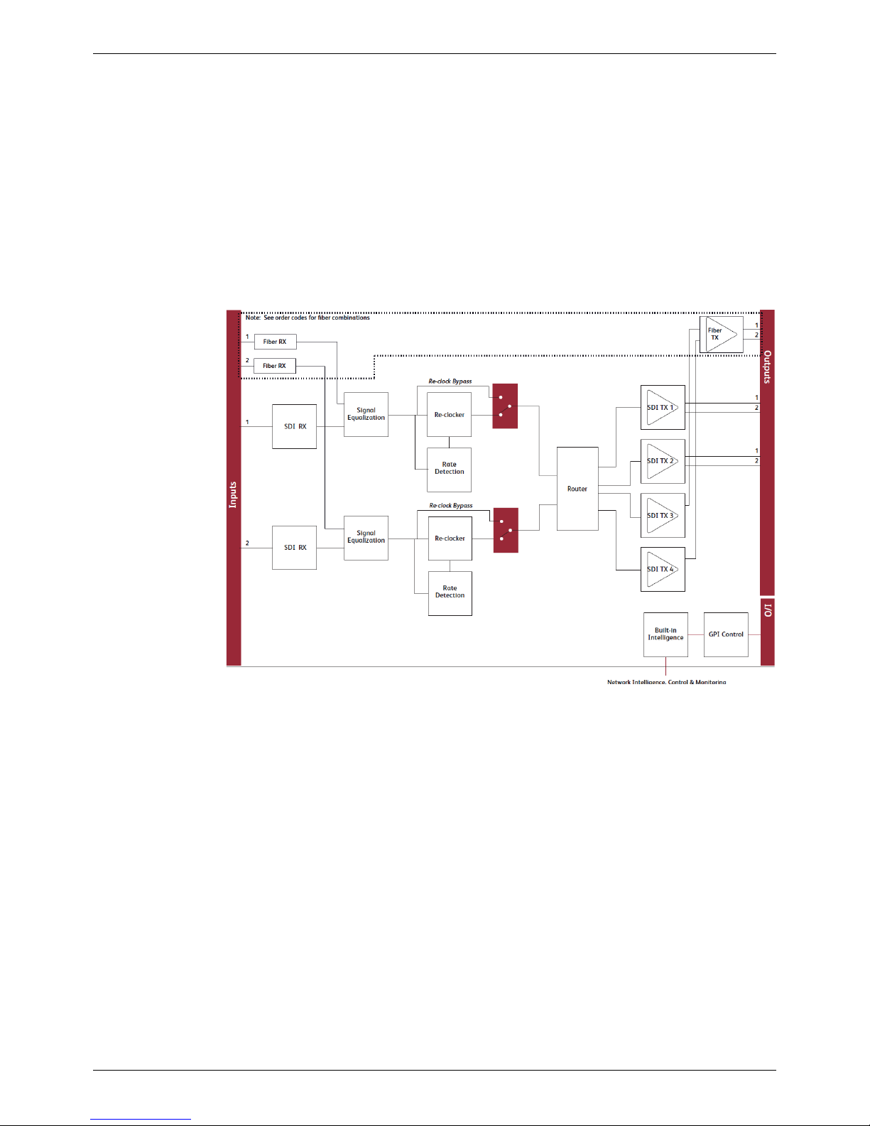
The IQFDA31 provides dual HD-SDI 3 Gbit/s, 1.5 Gbit/s, or 270 Mbit/s SD-SDI inputs with
both SDI and fiber optic outputs in a single-width package. Flexible routing of inputs and
outputs allows the module to operate as a single- o r dual-channel mixing fiber an d copper I/O.
Input signal loss detection enables switching from a main feed to a back-up feed
automatically, providing emergency changeover functionality. Its 80m 3G, 170m HD, and
300m SD input equalization performance and non re-clocking distribution of wide-band
signals make it ideal for all distribution applications.
1.2 Block Diagram
Page 5
IQFDA31 Introduction
Issue 1 Rev 1 Page 5 © 2016 SAM
1.3 Feature Summary
The IQFDA31 provides the following features:
• Dual-channel intelligent 3 Gbit/s SDI, HD-SDI, and SD-SDI re-clocking distribution
amplifier.
• Flexible selection of inputs allows single- or dual-channel operation.
• Input signal monitoring allows auto-changeover emergency switching.
• Provides distribution for DVB-ASI and other wide-band signals.
• Equalizes up to 80 m at 3 Gbit/s, 170 m at 1.5 Gbit/s and 300 m at 270 Mbit/s when
using Belden 1694A cable.
• Standards supported:
• 3G-HD to SMPTE 424M
• HD-SDI to SMPTE 292M
• SD-SDI to SMPTE 259M-C
• DVB-ASI
• SMPTE 297-2006
• 1310 nm, 1550 nm, and CWDM output waveleng th s ava ilab l e .
• RollCall monitoring allows all signal paths to be managed.
1.4 Order Codes
The following product order codes are covered by this manual:
The following SFP modules are available for this product:
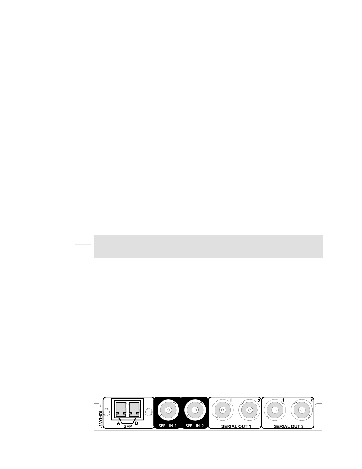
1.5 Rear Panel View
Note:
Modules with “A” order codes (for example, IQFDA3100-1 A3) can only be fitted into A-style
enclosures. Modules with “B” order codes (for example, IQFDA3100-1B3) can be fitted into
either A- or B-style enclosures. See page 6.
IQFDA3100-1A3
IQFDA3100-1B3
Dual-channel 3G/HD/SD-SDI re-clocking distribution amplifier with fiber
I/O. 2 SDI inputs, 2 optical inputs/outputs, 4 SDI outputs, selectable per
input.
FC1-13T1 1310 nm 1 TX
FC1-13T2 1310 nm 2 TX
FC1-15T1 1550 nm 1 TX
FC1-15T2 1550 nm 2 TX
FC1-R1 1 RX
FC1-TR 1 TX, 1 RX
Page 6
IQFDA31 Introduction
Issue 1 Rev 1 Page 6 © 2016 SAM
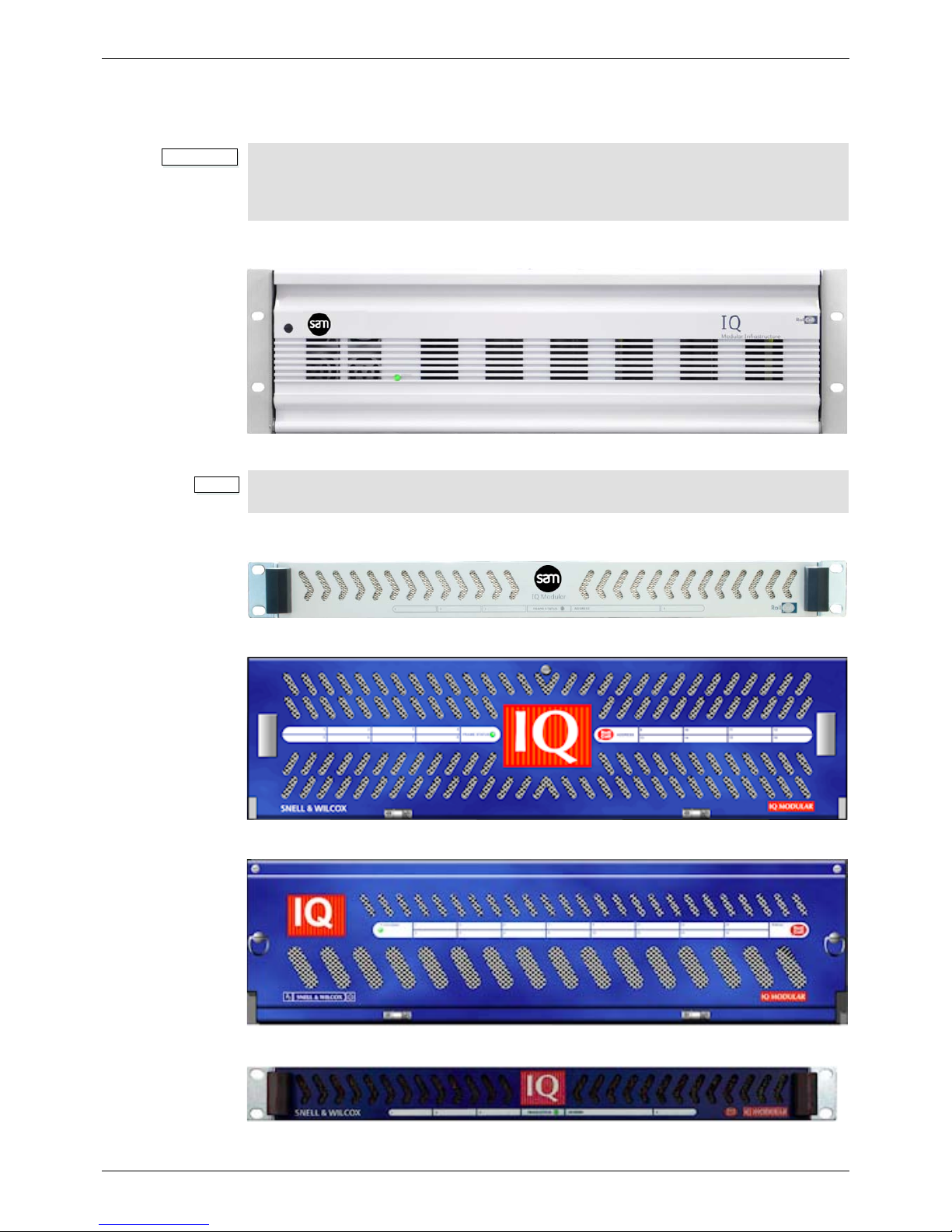
1.6 Enclosures
The module can be fitted into the enclosure types shown.
1.6.1 B-style Enclosure
Enclosure order codes: IQH3B-S-0, IQH3B-S-P
1.6.2 A-style Enclosures
Enclosure order code: IQH1A-S-P
Enclosure order codes: IQH3A-S-0, IQH3A-S-P
Enclosure order codes: IQH3A-E-0, IQH3A-E-P, IQH3A-0-0, IQH3A-0-P
Enclosure order code: IQH1A-S-P
Important:
Although IQ modules are interchangeable between enclosures, their rear panels are
enclosure specific. An IQH3B enclosure accepts modules with either “A” or “B” order
codes. An IQH3A or IQH1A enclosure accepts modules with “A” order codes only. See
page 5.
Note:
The IQH3B enclosure provides two internal analog reference inputs. These inputs are
applicable to modules with “B” order codes only.
Page 7

IQFDA31 Technical Specification
Issue 1 Rev 1 Page 7 © 2016 SAM
2 Technical Specification
Inputs and Outputs
Signal Inputs
SDI Inputs 2 x 3G/HD/SD-SD
Connector/Format BNC/75 Ohm panel jack on standard SAM connector panel
Input Cable Length Up to 80 m Belden 1694A @ 3 Gbit/s
Up to 170 m Belden 1694A @ 1.5 Gbit/s
Up to 300 m Belden 1694A @ 270 Mbit/s
Note: When using mixed HD and SD inputs, it is recommended that cable lengths do
not exceed the HD specification of 140 m.
Fiber Signal Input*
SDI Inputs Up to 2
Optical 3 Gbit/s HD-SDI
1.485 Gbit/s HD-SDI
270 Mbit/s SD-SDI
Connector/Format LC single mode
Conforms to SMPTE 297-2006
SMPTE 424M (HD level A/B)
SMPTE 292M (HD)
SMPTE 259M-C (SD)
Signal Outputs
SDI Outputs Up to 12, group selectable
Connector / Format BNC/75 Ohm panel jack on standard SAM connector panel
Conforms to video
standards
SMPTE 297-2006
SMPTE 424M (HD level A/B)
SMPTE 292M (HD)
SMPTE 259M-C (SD)
Fiber Signal Output*
SDI Outputs Up to 2, selectable per channel
Optical 3 Gbit/s HD-SDI
1.485 Gbit/s HD-SDI
270 Mbit/s SD-SDI
Connector/Format LC single mode
Conforms to SMPTE 297-2006
SMPTE 424M (HD level A/B)
SMPTE 292M (HD)
SMPTE 259M-C (SD)
*Dependant on SFP
fitted
Control Interface
GPI Up to 2 x GPI (I/O configurable)
Electrical TTL compatible, active low driven
Connector/Format BNC/ 75 Ohm panel jack on standard SAM connector panel
Controls
Indicators
Power OK (Green)
CPU OK (Green flashing)
Input 1 OK (Green), Bypass (Orange), Loss (Red)
Page 8

IQFDA31 Technical Specification
Issue 1 Rev 1 Page 8 © 2016 SAM
Input 2 OK (Green), Bypass (Orange), Loss (Red)
SFP A OK (Green), Bypass (Orange), Loss (Red)
SFP B OK (Green), Bypass (Orange), Loss (Red)
RollCall Functions
Video Controls
Input 1 Format Select SDI, Rx
Input 2 Format Select SDI, Rx
Output 1 Select Serial 1, Serial 2
Output 2 Select Serial 1, Serial 2
Output 3 Select Serial 1, Serial 2
Output 4 Select Serial 1, Serial 2
Laser Disable On/Off
Input 1 (2) Auto, 3G, HD, SD, DVB-ASI, Bypass (re-clocking off), Output
Input Status Present, Loss, Unknown, Data Rate
Other Controls
User Memories Name, save, and recall 16 user memories
Memory Naming User configurable naming of memories 1–16
GPI Input Activates on contact closure – select config 1 or 2
GPI Output Produces an output for: Config 1 selected, Config 2 selected, Input 1 error, Input 2
error
Information Window Unit Status, SFP Status
Logging Input 1(2) Type
Input 1 (2) Data Rate
Input 1 (2) Present
Input 1 (2) Error
Input 1 (2) Loss
Optical Logging Tx Laser Bias High Warning
Tx Power Low Warning
Tx Power High Warning
Laser Wavelength Input 1 (2) Rx Power High Warning
Input 1 (2) Rx Power Low Warning
Input 1 (2) Rx Power Measurement
RollTrack Index Up to 16 RollTrack destinations
RollTrack Controls On/Off, Index, Source, Address, Command, Status, Sending
Roll Track Sources Unused, Input Present (1 & 2, Fiber 1 & 2), Input Loss (1 & 2, Fiber 1 & 2), Output
Rate/Std (1 & 2), Out 1 Selects (In 1 & 2 & Rx 1 & Rx 2), Fiber Rx Power OK (1 & 2),
Fiber Rx Power Fail (1 & 2), Fiber Tx Bias OK (1 & 2), Fiber Tx Bias High (1 & 2), Fiber
Tx Bias Low (1 & 2)
Factory Default Resets all module settings to factory specified default va lues and clears memories
Default Settings Resets all module settings to factory specified default values but does not clear
memories
Restart Software restart of the module
Module Information Reports the following module information: Software Version, Serial Number, Build
Number, KOS Version, Firmware Version, PCB Version
Specifications
Electrical 3 Gbit/s SDI, SMPTE 424M
1.5 Gbit/s HD-SDI, SMPTE 292M
270 Mbit/s SDI, SMPTE 259M-C / DVB-ASI
Page 9

IQFDA31 Technical Specification
Issue 1 Rev 1 Page 9 © 2016 SAM
Connector / Format BNC/ 75 Ohm
LC singlemode SFP
Return Loss >-15 dB (270 Mbit/s, 1.5 Gbit/s)
>-10 dB (3 Gbit/s)
Output Jitter SD-SDI 0.2 UI (10 Hz) / 0.2 UI (1 kHz)
3G/HD-SDI 1.0 UI (10 Hz) / 0.2 UI (100 kHz)
Optical 1310 nm Tx
Wavelength 1310 nm
Spectral Widt h (FWHM) >1.5 nm (typical)
Output Power 0 to -5 dBm (-2 dBm typical)
Rise and Fall Time 135 ps @ 3 Gbit/s
270 ps @ 1.5 Gbit/s
1.5 ns @ 270 Mbit/s
Extinction Ratio >7.5:1 (typical)
Optical Return Loss -27 dB
Link Distance Up to 30 Km @ 3 Gbit/s
Up to 21 Km @ 1.5 Gbit/s
Up to 10 Km @ 270 Mbit/s
Optical Rx
Input Wavelength Range 1260 nm (min.), 1620 nm (max.)
Input Sensitivity -21 dBm
Optical Power Input
Range
>0 dBm, <-20 dBm
Link Distance Up to 30 Km @ 3 Gbit/s
Up to 21 Km @ 1.5 Gbit/s
Up to 10 Km @ 270 Mbit/s
Power Consumption
Module Power
Consumption
4 W Max (A frames)
4 PR Max (B frames)
Page 10
IQFDA31 Connections
Issue 1 Rev 1 Page 10 © 2016 SAM
3 Connections
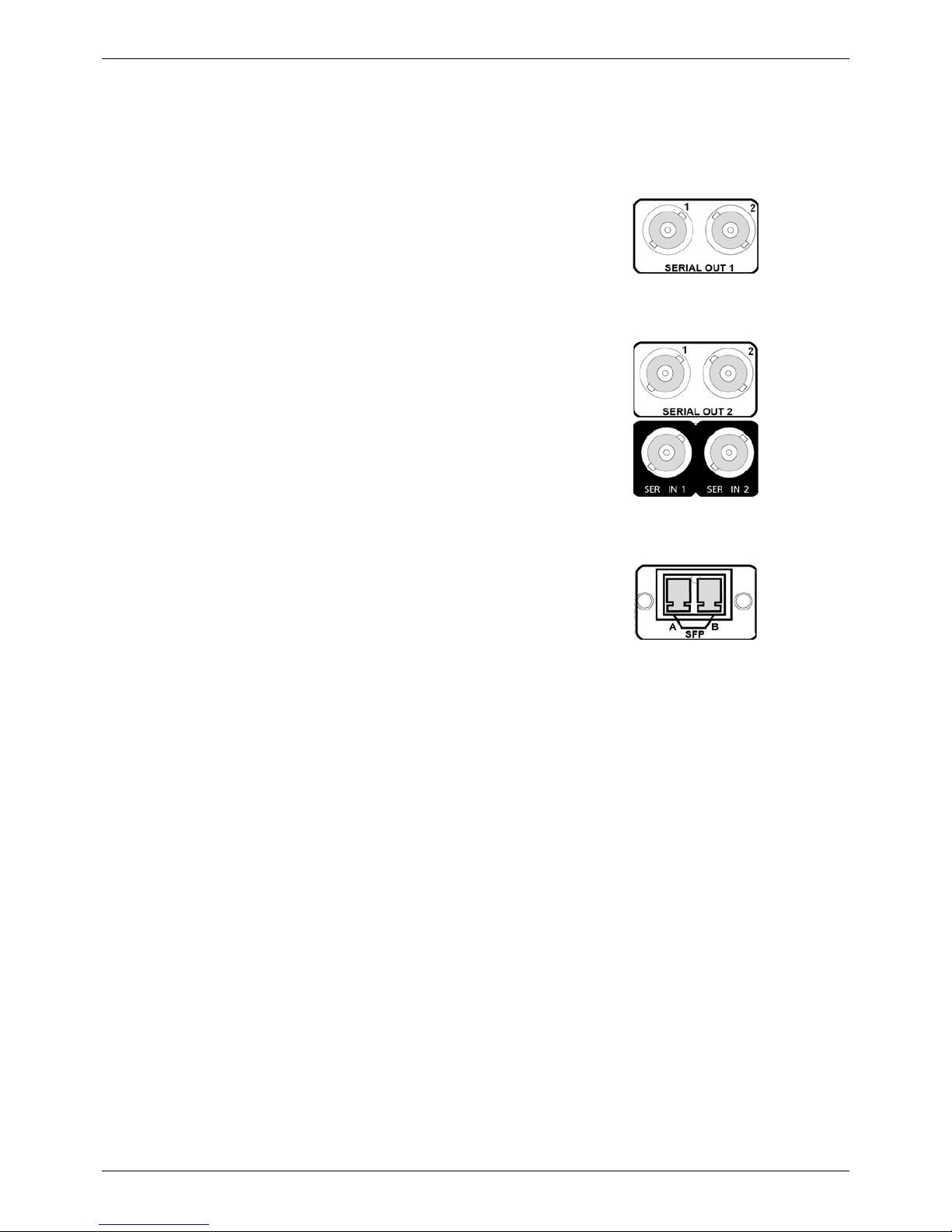
This section describes the physical input and output connections provided by the IQFDA31.
3.1 SDI Input
3.2 SDI Outputs
3.3 SFP
Serial digital input is made to the unit via two
BNC connectors which terminate in
75 Ohms.
Serial digital outputs from the unit are made
via four BNC connectors which terminate in
75 Ohms.
An SFP cage provides a range of
connectivity options.
Page 11
IQFDA31 Card Edge LEDs
Issue 1 Rev 1 Page 11 © 2016 SAM
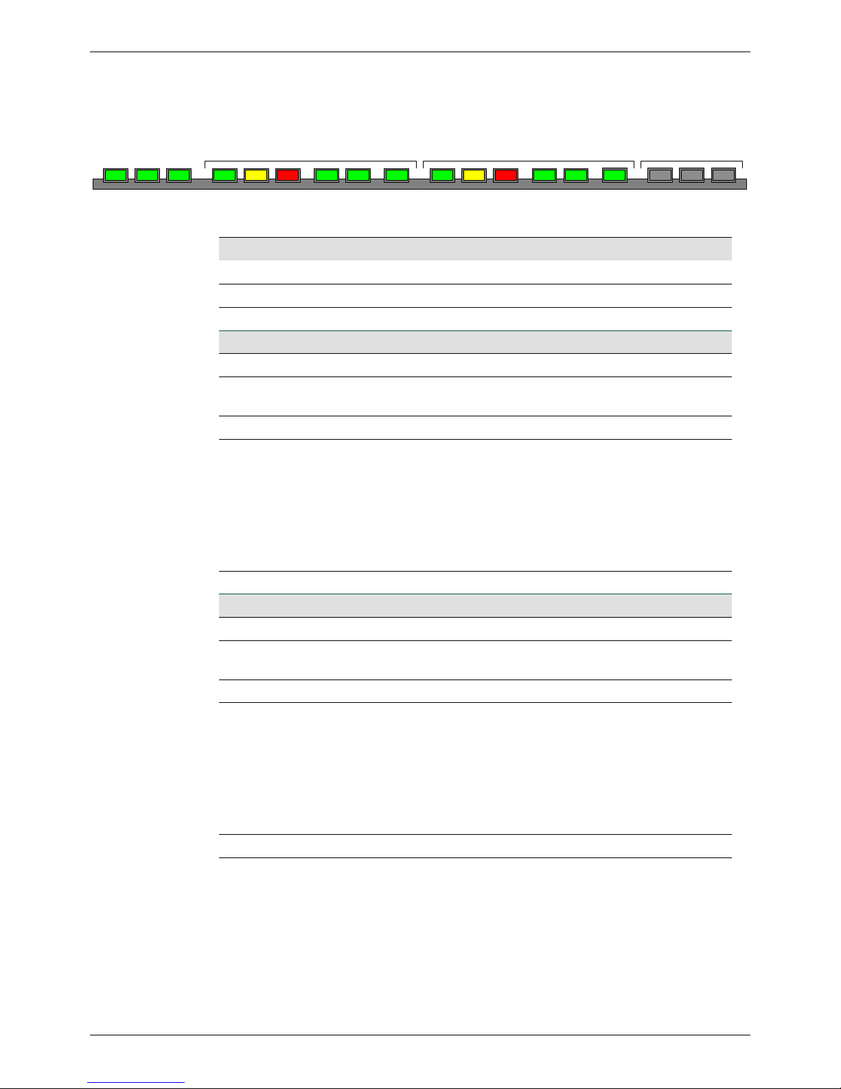
4 Card Edge LEDs
The LEDs on the edge of the module indicate its operating status.
POWER+POWER-MON
RUN
OK WARN ERR RATE SFP
CHANNEL B (Input 2) STATUS – Not usedCHANNEL A (Input 1)
WARN ERR RATE SFP
LED Color State Indication
POWER + Green Illuminated A positive power supply is present.
POWER - Green Illuminated A negative power supply is present.
MON RUN Green Flashing The CPU is running.
CHANNEL A
OK Green Illuminated Input channel 1 is locked to the input signal.
WARN Yellow Illuminated The signal on input channel 1 is not being
re-clocked. That is, in re-clock bypass mode.
ERR Red Illuminated Unknown or no input on input channel 1.
RATE Green Illuminated The rate on input channel 1:
• Both LEDs illuminated: 3 Gbit/s
• Left LED illuminated: 1.5 Gbit/s
• Right LED illuminated: 270 Mbit/s
• Both LEDs off: Rate unknown
SFP Green Illuminated Input SFP Rx A selected.
CHANNEL B
OK Green Illuminated Input channel 2 is locked to the input signal.
WARN Yellow Illuminated The signal on input channel 2 is not being
re-clocked. That is, in re-clock bypass mode.
ERR Red Illuminated Unknown or no input on input channel 2.
RATE Green Illuminated The rate on input channel 2:
• Both LEDs illuminated: 3 Gbit/s
• Left LED illuminated: 1.5 Gbit/s
• Right LED illuminated: 270 Mbit/s
• Both LEDs off: Rate unknown
SFP Green Illuminated Input SFP Rx selected.
Page 12
IQFDA31 Operation Using the RollCall Control Panel
Issue 1 Rev 1 Page 12 © 2016 SAM
5 Operation Using the RollCall Control Panel
5.1 Information Window
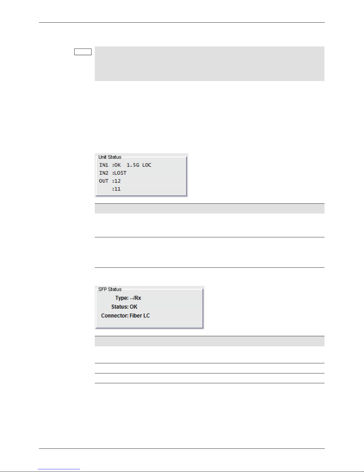
The Information Window is displayed in the upper-right corner of each screen and displays
basic information about the input and output status of the module.
5.1.1 Unit Status
The Unit Status pane provides basic information about the status of the video inputs, video
outputs, product settings, and status.
5.1.2 SFP Status
Note:
The IQFDA31 will dynamically configure itself depending on rear and SFP options. The
RollCall control panel will change to reflect the current product configuration.
The screens shown in this section are for guidance and reference only, and may be slightly
different to those on your module.
Name Description
IN1:
IN2:
Displays the status of Input 1 and Input 2, the detected
rate, and whether the signal is locked or in byp ass mode. If
no valid input is detected, asterisks (**) are displayed.
OUT:
The first line represents the outputs (1–4 ). The second line
is character aligned with the first and indicates the input
routed to that output. If no valid input signal is detected for
the output, an E is displayed.
Name Description
Type:
Shows the type of SFP installed. This is supplemented
with a simple report for each SFP.
Status: Shows the operational status of the SFP.
Connector: Shows the physical connector type, for example, Fiber LC.
Page 13
IQFDA31 Operation Using the RollCall Control Panel
Issue 1 Rev 1 Page 13 © 2016 SAM
5.2 Input
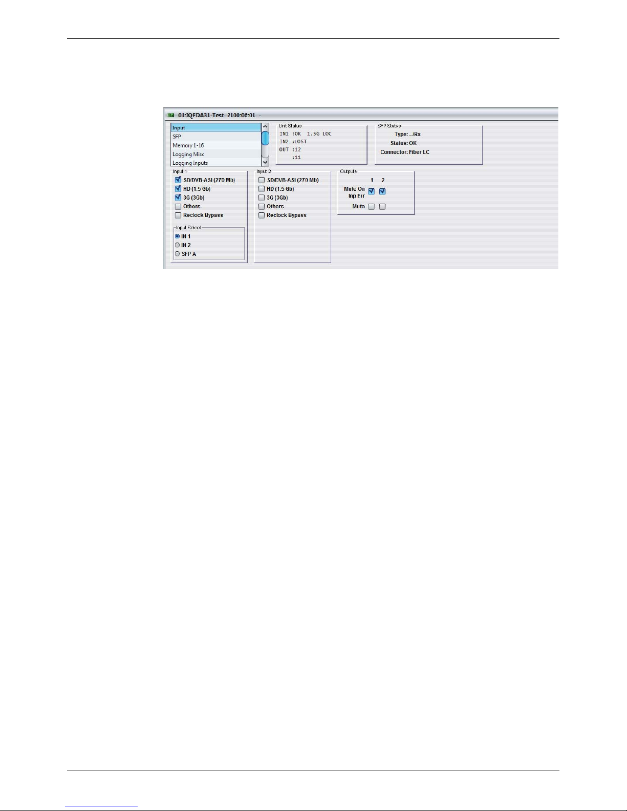
The Input screen enables the inputs and outputs to be configured, and can be used to
determine how the module behaves in the event of an input error.
5.2.1 Input 1 and 2
• SD/DVB-ASI (270 Mb): When selected, the unit will re-clock SD/DVB-ASI (270 Mb)
signals.
• HD (1.5 Gb): When selected, the unit will re-clock HD (1.5 Gb) signals.
• 3G (3 Gb): When selected, the unit will re-clock 3G (3 Gb) signals.
• Others: When selected, signals that are not of any of the above rates will be
re-clocked.
• Reclock Bypass: When selected, the unit will not re-clock the input signal. If a
supported rate is detected, the Unit Status will display the detected rate, otherwise, ***
will be displayed.
• Input Select: Use the radio buttons to select the input.
5.2.2 Outputs
Use the radio buttons to specify the input for each of the outputs.
Select Mute On Inp Err to apply a mute to the output if any rate other than those specified as
valid in the Input 1 and Input 2 sections is detected.
Select Mute to manually apply a mute to the output.
Page 14
IQFDA31 Operation Using the RollCall Control Panel
Issue 1 Rev 1 Page 14 © 2016 SAM
5.3 SFP
5.3.1 SFP Transmit
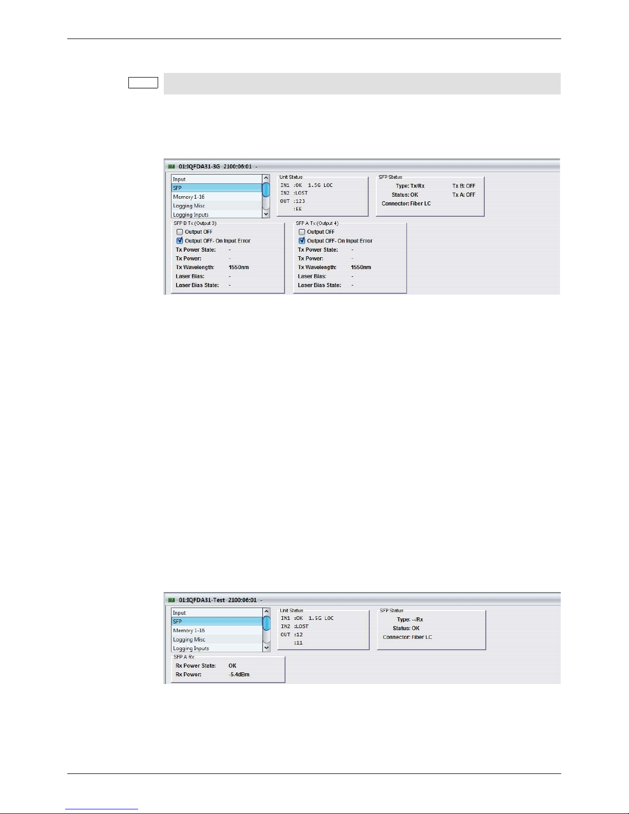
For an SFP transmitter channel, the SFP screen is used to select whether the output is turned
off – either permanently, or when an error condition on the selected input is detected.
5.3.1.1 SFP B Tx
• Output OFF: Enables the fiber optic output to be turned off manually.
• Output OFF- On Input Error: When selected, enables the fiber optic output to be
turned off automatically when the signal is lost at the associated fiber optic receiver
input.
• Tx Power State: Displays the state of the transmitted output signal (options include
OK, WARN:HI, WARN:LO, FAIL:LO and FAIL:HI).
• Tx Power: Displays the signal level of the transmitted output signal (in dBm).
• Tx Wavelength: Displays the wavele ngth of the transmitted output signal (either 1310
nm or 1550 nm).
• Laser Bias: Displays the bias level (in mA).
• Laser Bias Stat e: Displays the bias st ate (options include OK, WARN:HI, WARN:LO,
FAIL:LO and FAIL:HI).
5.3.2 SFP Receive
For an SFP receiver channel, the SFP report s the status of the SFP. If a deselected data rate
is presented to the module t will cause an “On Error” condition and the module will handle this
as per its On Error settings on the Translate screen.
5.3.2.1 SFP A Rx
• Rx Power State: Displays the state of the received signal (options include OK,
WARN:HI, WARN:LO, FAIL:LO and FAIL:HI).
• Rx Power: Displays the signal level received at the input (in dBm).
Note:
This screen is only displayed when the module is fitted with a rear that supports SFPs.
Page 15
IQFDA31 Operation Using the RollCall Control Panel
Issue 1 Rev 1 Page 15 © 2016 SAM
5.4 Memory 1-16
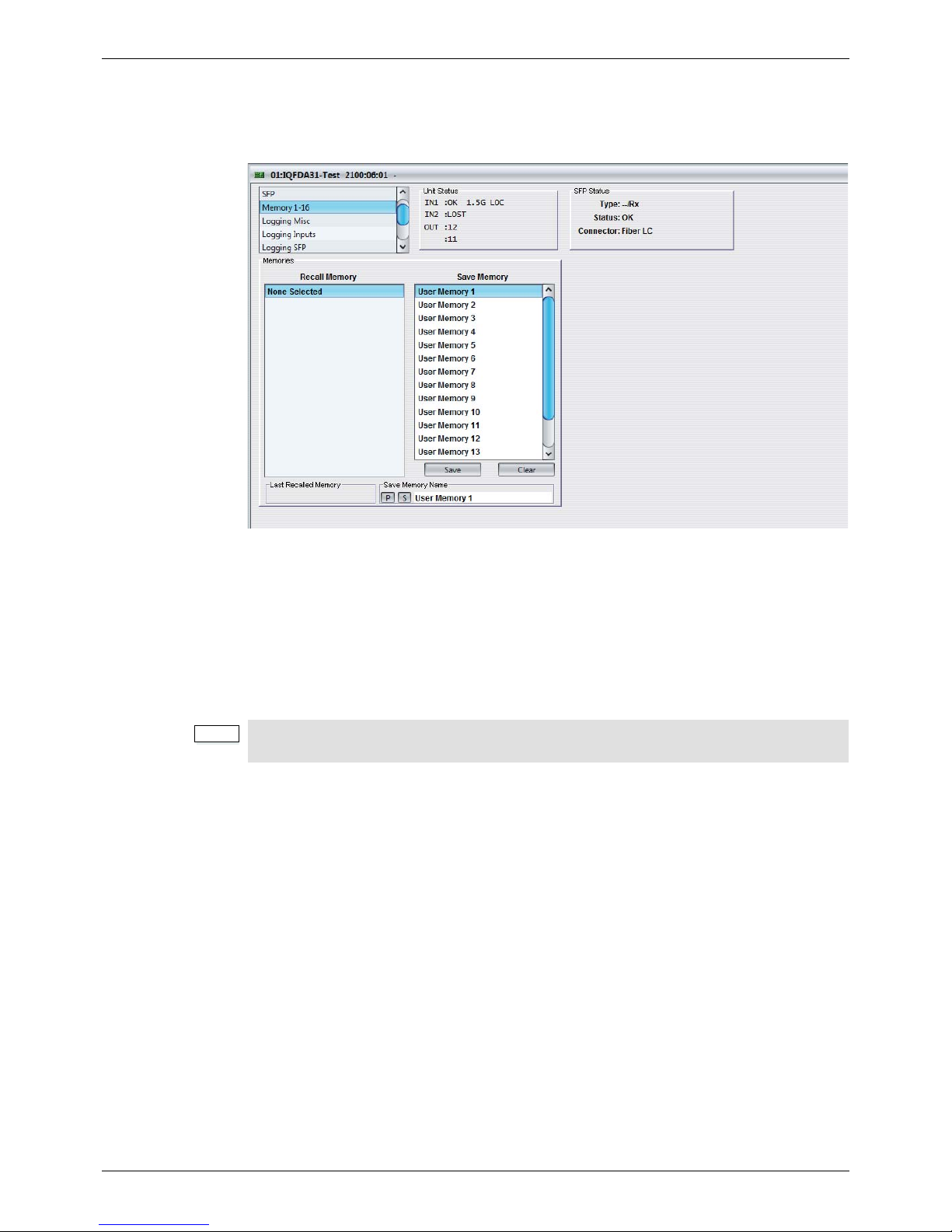
The Memory 1-16 screen enables up to 16 setups to be saved and recalled later. Default
memory names can be changed to provide more meaningful descriptions.
5.4.1 Recall Memory
This column lists the settings that have been previously saved. If no settings have been
saved, None Selected is displayed.
To recall the settings saved in a memory:
• In the Recall Memory column, select the memory to recall by clicking on it. The
recalled settings will be applied and the memory name will appear in the Last
Recalled Memory section.
5.4.2 Save Memory
This column lists the 16 pre-set memory names that are available for use.
To save settings:
• In the Save Memory column, select a memory location, and then click Save. The
current settings are saved and the memory appears in the Recall Memory column.
To clear a memory location:
• In the Save Memory column, select a memory location, and then click Clear. The
current settings stored for that memory are cleared. After you clear a memory
location, it disappears from the Recall Memory list.
5.4.3 Last Recalled Memory
The Last Recalled Memory pane displays the most recently recalled memory. If any o f the
settings have been changed since it was recalled, an asterisk will be displayed after the
memory name.
Note:
User memories do not recall log field “states” – that is, whether a log value has been
enabled or disabled.
Page 16

IQFDA31 Operation Using the RollCall Control Panel
Issue 1 Rev 1 Page 16 © 2016 SAM
5.4.4 Save Memory Name
This option enables the pre-set memory names to be changed (to something more
memorable or meaningful), if required.
To change a memory name:
• In the Save Memory Name field, type the new memory name, and then click the S
button. To return the memory to its default preset value, click P button.
Page 17
IQFDA31 Operation Using the RollCall Control Panel
Issue 1 Rev 1 Page 17 © 2016 SAM
5.5 Logging
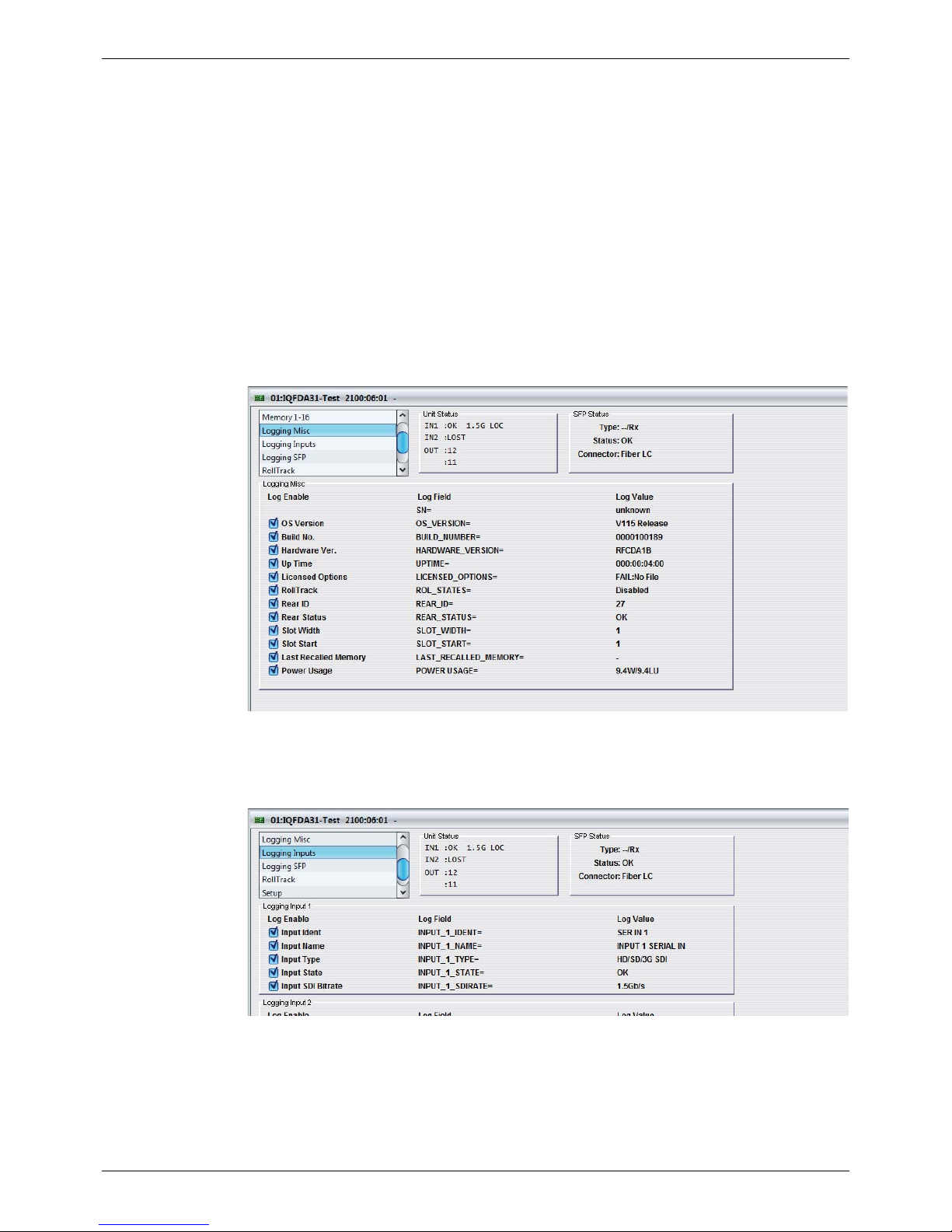
Information about several parameters can be made available to a logging device that is
connected to the RollCall network.
Each logging screen comprises three columns:
• Log Enable: Select the check boxes that correspond to the parameters for which log
information should be collected.
• Log Field: Displays the name of the logging field.
• Log Value: Displays the current log value.
5.5.1 Logging Misc
The Logging Misc screen displays the current log information about the unit’s basic
parameters.
5.5.2 Logging Inputs
The Logging Inputs screen is used to select which fields should be enabled for each of the
serial inputs.
Page 18
IQFDA31 Operation Using the RollCall Control Panel
Issue 1 Rev 1 Page 18 © 2016 SAM
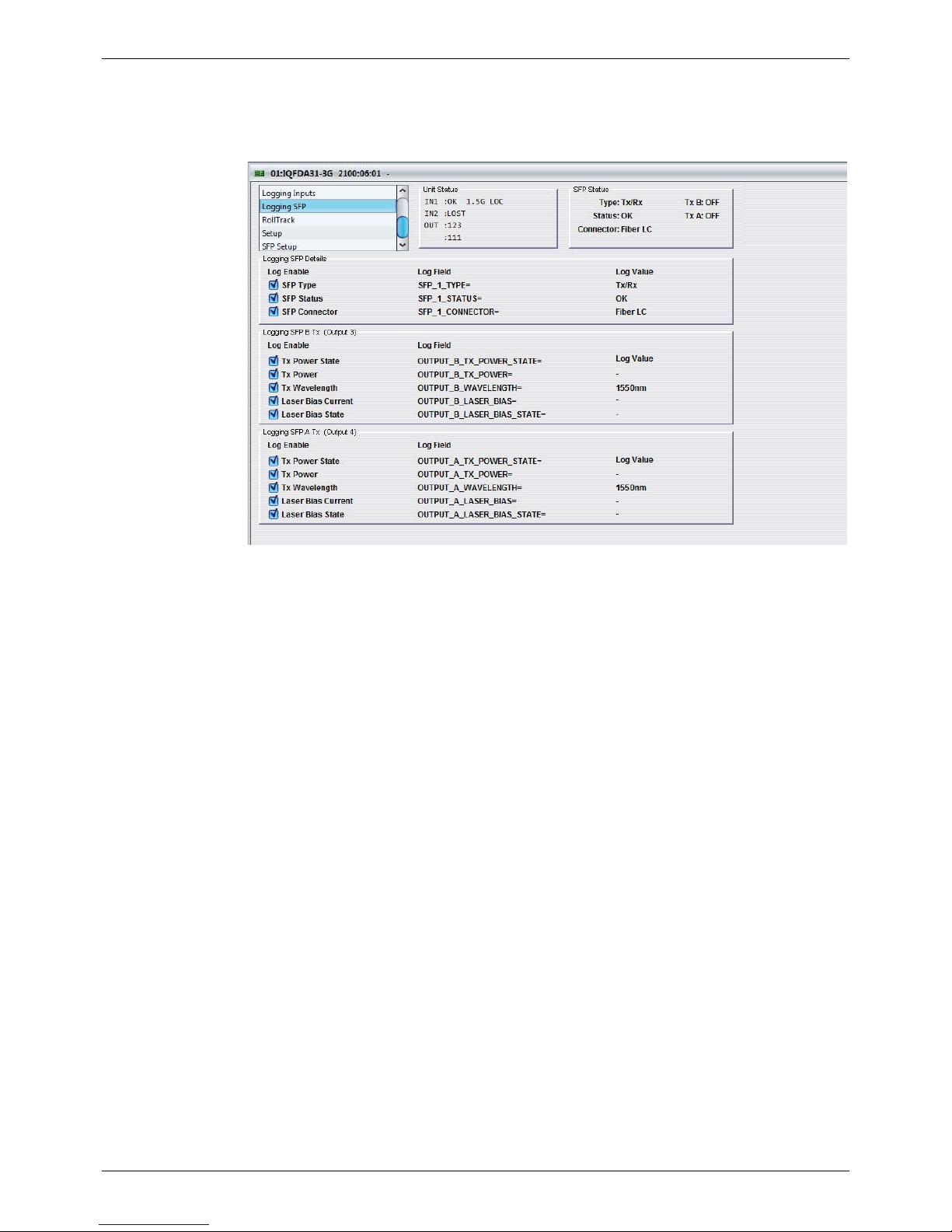
5.5.3 Logging SFP
The Logging SFP screen is used to select which fields should be enabled for each of the SFP
inputs.
Page 19
IQFDA31 Operation Using the RollCall Control Panel
Issue 1 Rev 1 Page 19 © 2016 SAM
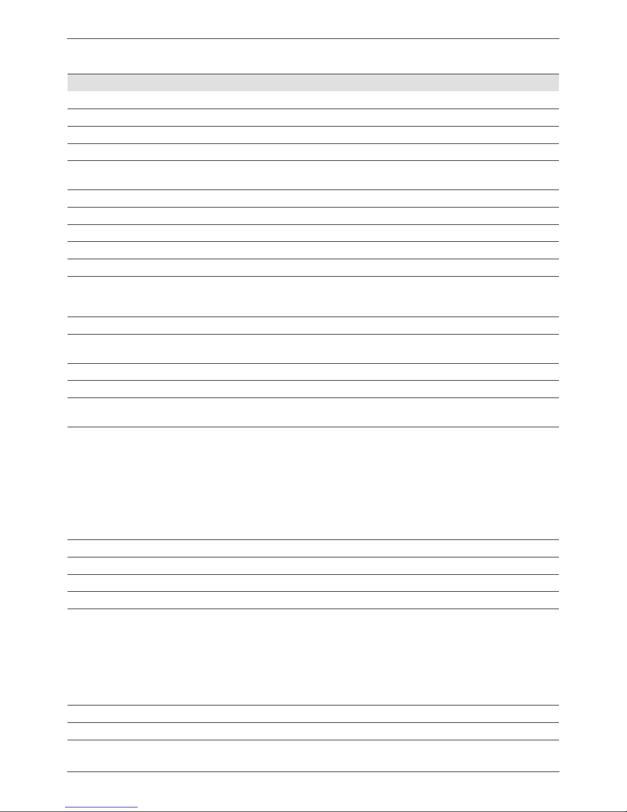
5.5.4 Log Field Descriptions
Log Field Description
SN= The module’s unique serial number.
OS_VERSION= The operating system version.
BUILD_NUMBER= The software build number.
HARDWARE_VERSION The hardware build version.
UPTIME= Shows the time since the last restart (format
ddd:hh:mm:ss).
LICENSED_OPTIONS= The licensed features installed in the module.
ROL_STATES= The status of any RollTracks that have been enabled.
REAR_ID= The rear panel type.
REAR_STATUS= The status of the rear panel.
SLOT_WIDTH= The number of slots used by rear and module.1 or 2.
SLOT_START= The first slot number the rear occupies. Use in
conjunction with SLOT_WIDTH to determine the slots
that the unit occupies.
LAST_RECALLED_MEMORY= The last recalled memory.
POWER USAGE= The power rating for the module. Note: this is not a live
power reading.
INPUT_N_IDENT= The identifier of the serial data input.
INPUT_N_NAME= The name of the serial data input.
INPUT_N_TYPE= This displays the type of input as specified by the unit’s
configuration. Valid values are HD /SD SDI.
INPUT_N_STATE= Displays the current input state. Valid values are:
•OK
• WARN:Mismatch
•FAIL:Lost
•FAIL:Error
Note: WARN:Mismatch indicates that the input and
output standards are not the same.
INPUT_N_SDIRATE= The current bit rate for the serial data input.
SFP_N_TYPE= The transmitter type.
SFP_N_STATUS= The status of the SFPs as reported by the SFPs.
SFP_N_CONNECTOR= The physical connector type, for example, Fiber LC.
OUTPUT_N_TX_POWER_STATE= Displays the TX power status. Valid values are:
•OK
•WARN:HI
•WARN:LO
•FAIL:LO
•FAIL:HI
OUTPUT_N_TX_POWER= The power level of the TX input, in dBm.
OUTPUT_N_WAVELENGTH= The wavelength of the transmitted output signal.
Page 20
IQFDA31 Operation Using the RollCall Control Panel
Issue 1 Rev 1 Page 20 © 2016 SAM
OUTPUT_N_LASER_BIAS= The bias level, in mA.
OUTPUT_N_LASER_BIAS_STATE= Displays the laser bias status. Valid values are:
•OK
•WARN:HI
•WARN:LO
•FAIL:LO
•FAIL:HI
Log Field Description
Note:
N should be replaced with the respective SFP/output identifier, for example, 1 for an SFP
and B for an output.
Page 21
IQFDA31 Operation Using the RollCall Control Panel
Issue 1 Rev 1 Page 21 © 2016 SAM
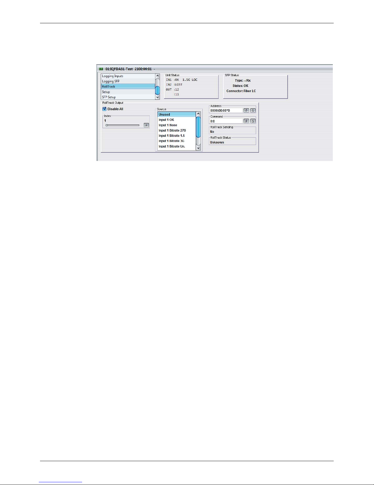
5.6 RollTrack
The RollTrack screen allows information to be sent, via the RollCall™ network, to other
compatible units connected on the same network.
5.6.1 Disable All
When checked, all RollTrack items are disabled.
5.6.2 Index
This slider enables up to 16 RollTrack outputs to be setup. Dragging the slider selects the
RollTrack Index number, displayed below the slider. Clicking the P button selects the default
preset value.
5.6.3 Source
This slider enables the source of information that triggers the transmission of data to be
selected. Dragging the slider selects the RollTrack source, displayed below the slider.
Clicking the P button selects the default preset value. When no source is selected, Unused is
displayed.
Unused No RollTracks sent.
Input N OK Valid serial data input received.
Input N None No serial data input received.
Input N Bitrate 270 Received bitrate is 270 Mbit/s.
Input Bitrate 1.5 Received bitrate is 1.5 Gbit/s.
Input N Bitrate 3G Received bitrate is 3 Gbit/s.
Input N Bitrate Un. Received bitrate is unknown.
TX N Bias OK LASER Bias current within limits.
TX N Bias High LASER Bias current above limits.
TX N Bias Low LASER Bias current below limits.
RX N Power OK Receive power is within limits.
RX N Power High Receive power is above limits.
RX N Power Low Receive power is below limits.
Page 22

IQFDA31 Operation Using the RollCall Control Panel
Issue 1 Rev 1 Page 22 © 2016 SAM
5.6.4 Address
This item enables the address of the selected destination unit to be set.
The address may be changed by typing the new destination in the text area and then
selecting the S button to save the selection. Clicking the P button returns to the default preset
destination.
The RollTrack address consists of four sets of numbers, for example, 0000:10:01*99.
• The first set (0000) is the network segment code number.
• The second set (10) is the number identifying the (enclosure/mainframe) unit.
• The third set (01) is the slot number in the unit.
• The fourth set (99) is a user-defined unique identification number for the destination
unit in a multi-unit system. This ensures that only the correct unit will respond to the
command. If left at 00 an incorrectly fitted unit may respond unexpectedly.
5.6.5 Command
This item enables a command to be sent to the selected destination unit.
The command may be changed by typing a code in the text area and then selecting the S
button to save the selection. Clicking the P button returns to the default preset command.
The RollTrack command consists of two sets of numbers, for example: 84:156.
• The first number (84) is the actual RollTrack command.
• The second number (156) is the value sent with the RollTrack command.
5.6.6 RollT rack Se nding
A message is displayed here when the unit is actively sending a RollTrack command.
Possible RollTrack Sending messages are:
5.6.7 RollT rack Status
A message is displayed here to indicate the status of the currently selected RollTrack index.
Possible RollTrack Status messages are:
String A string value is always being sent.
Number A number value is always being sent.
No The message is not being sent.
Yes The message is be ing sen t.
Internal Type Error Inconsistent behavior. Please contact your local SAM agent.
OK RollTrack message sent and received OK.
Unknown RollTrack message has been sent but it has not yet completed.
Timeout RollTrack message sent but acknowledgement not received. This
could be because the destination unit is not at the location specified.
Bad RollTrack message has not been correctly acknowledged at the
destination unit. This could be because the destination unit is not of
the type specified.
Disabled RollTrack sending is disabled.
Page 23
IQFDA31 Operation Using the RollCall Control Panel
Issue 1 Rev 1 Page 23 © 2016 SAM
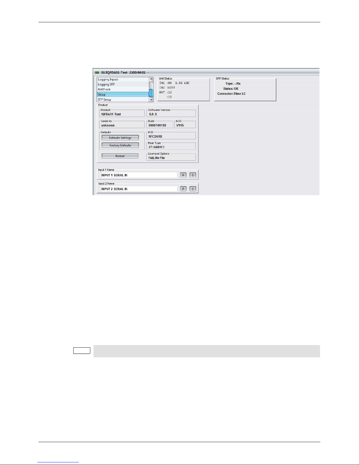
5.7 Setup
The Setup screen display basic information about the module, such as th e serial numb er and
software versions. Use the functions on the screen to restart the module or return all settings
to their factory or default settings.
• Product: The name of the module.
• Software Version: The currently installed software version number.
• Serial No: The module serial number.
• Build: The factory build number. This number identifies all parameters of the module.
• KOS: The operating system version number.
• PCB: The Printed Circuit Board revision number.
• Rear Type: The rear panel type.
• Licensed Options: The installed licensed options.
5.7.1 Default Settings
The Default Settings button enables module settings to be reset to their factory defaults,
leaving user memories intact.
5.7.2 Factory Defaults
The Factory Defaults button ena bles the mo du le settings to be re se t to their factory defaults.
5.7.3 Restart
The Restart button enables the module to be rebooted, simulating a power-up/power-down
cycle.
5.7.4 Input Name
These are the input names displayed in logging.
To change the name of Input 1 or Input 2, type the name in the text field and click S. To return
the name to its factory default, click P.
Note:
Resetting the module to its factory defaults also clears all the saved memory settings.
Page 24
IQFDA31 Operation Using the RollCall Control Panel
Issue 1 Rev 1 Page 24 © 2016 SAM
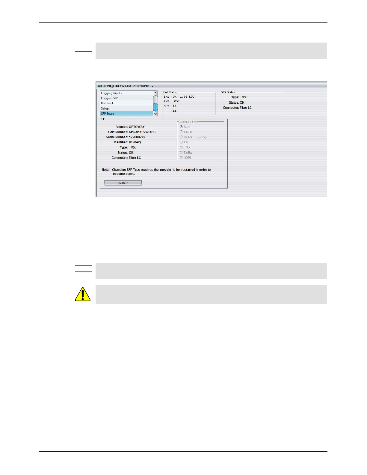
5.8 SFP Setup
The SFP Setup screen displays basic information about the SFP configuration. If the SFP is
not recognized, manual configuration is available.
5.8.1 Restart
The Restart button enables the module to be rebooted, simulating a power-down/power-up
cycle.
5.8.2 Configure Type
In the event of the module not recognizing the SFP, the Configure T ype controls will become
available for manual selection.
Note:
The SFP Setup screen is only displayed when the module is fitted with a rear that supports
SFPs, even if no SFP is fitted.
Note:
When changing an SFP, the module needs to be restarted in order for the SFP to become
active.
Before configuring the SFP, ensure that the correct SFP is installed.
 Loading...