

SalvisLab VC20, VC50 Instruction Manual
Vacucenter VC20 / VC50
ew
User Manual
Copyright © SalvisLab / Edition 191107 Copyright © SalvisLab / Edition 191107
swiss made

User Manual Vacucenter VC20, VC50
CE DECLARATON OF CONFIRMITY...............................................................................................................4
IMPORTANT INFORMATION............................................................................................................................5
QUICK INFORMATION FOR SERVICE ....................................................................................................................5
TECHNICAL DATA’S ........................................................................................................................................6
TECHNICAL DATA’S VACUUM DRYING OVEN........................................................................................................6
INTRODUCTION ................................................................................................................................................7
OVERVIEW ........................................................................................................................................................7
APPLICATIONS...................................................................................................................................................7
CONSTRUCTION ................................................................................................................................................7
VACUUM AND AIR SYSTEMS ...............................................................................................................................7
CONTROLLER ....................................................................................................................................................8
SAFETY ............................................................................................................................................................8
GETTING STARTED..........................................................................................................................................9
PARTS DELIVERED.............................................................................................................................................9
INSTALL REQUIREMENTS ....................................................................................................................................9
INSTALLING .......................................................................................................................................................9
CLEANING .........................................................................................................................................................9
SYSTEM COMPONENTS................................................................................................................................10
CONTROLLER.................................................................................................................................................11
KEYPAD & DISPLAY .........................................................................................................................................11
OPERATING ....................................................................................................................................................12
HOW TO INTERPRET DISPLAYS DESCRIBED IN THIS MANUAL................................................................................12
MAIN MENU - OVERVIEW .................................................................................................................................13
1 MAIN MENU - TEMP & OPTIONS ....................................................................................................................14
2 MAIN MENU - PROGRAM ...............................................................................................................................16
2.1 MENU PROGRAM - START ..........................................................................................................................17
2.2 MENU PROGRAM - NEW.............................................................................................................................18
2.3 MENU PROGRAM- EDIT..............................................................................................................................20
2.4 MENU PROGRAM - DELETE ........................................................................................................................23
2.5 MENU PROGRAM - PRINT...........................................................................................................................23
3 MAIN MENU - CONFIGURATION......................................................................................................................24
4 MENU SERVICE MODE ..................................................................................................................................26
STATUS DISPLAYS ........................................................................................................................................27
GENERAL........................................................................................................................................................27
5 STATUS DISPLAY: MANUAL MODE – DEFINED START-DATE............................................................................27
6 STATUS DISPLAY: MANUAL MODE – PROCESS RUNNING................................................................................27
7 STATUS DISPLAY: PROGRAM MODE - DEFINED PROGRAM START DATE...........................................................28
8 STATUS DISPLAY: PROGRAM MODE - PROGRAM RUNNING..............................................................................28
9 CANCEL A RUNNING PROCESS BY ESC KEY...................................................................................................29
10 MESSAGES AND ERRORS ............................................................................................................................29
PRINTER OPERATION ...................................................................................................................................30
CONNECTING A PRINTER .................................................................................................................................30
EXAMPLES OF DIFFERENT PRINTER OUTPUTS ....................................................................................................30
APPENDIX A....................................................................................................................................................31
HYSTERESIS VALUE FOR THE VACUUM-CONTROL .............................................................................................31
GRAPHS OF TEMPERATURE LIMITS AND GRADIENT AND PROGRAM-RUN..............................................................31
RANGE OF GRADIENT .......................................................................................................................................31
GRAPHICAL PRESENTATION OF A PROGRAM-RUN...............................................................................................32
- 2 - Copyright © SalvisLab / Edition 191107

APPENDIX B ................................................................................................................................................... 33
MENU STRUCTURE & INPUT FIELDS................................................................................................................. 33
APPENDIX C ................................................................................................................................................... 34
WIRING DIAGRAM VC 20................................................................................................................................. 34
APPENDIX D ................................................................................................................................................... 35
WIRING DIAGRAM VC 20 WITH VALVE CONTROL .............................................................................................. 35
APPENDIX E ................................................................................................................................................... 36
WIRING DIAGRAM VC 20 WITH VALVE- / PUMP CONTROL ................................................................................. 36
APPENDIX F ................................................................................................................................................... 37
WIRING DIAGRAM VC 50................................................................................................................................. 37
APPENDIX G................................................................................................................................................... 38
WIRING DIAGRAM VC 50 WITH VALVE CONTROL .............................................................................................. 38
APPENDIX H ................................................................................................................................................... 39
WIRING DIAGRAM VC 50 WITH VALVE- / PUMP CONTROL ................................................................................. 39
APPENDIX I..................................................................................................................................................... 40
DRAWING VC 20 ............................................................................................................................................ 40
APPENDIX J.................................................................................................................................................... 41
DRAWING VC 50 ............................................................................................................................................ 41
APPENDIX K ................................................................................................................................................... 42
DRAWING SPARE PARTS PANEL ...................................................................................................................... 42
APPENDIX L ................................................................................................................................................... 43
DRAWING SPARE PARTS DOOR....................................................................................................................... 43
APPENDIX M................................................................................................................................................... 44
DRAWING SPARE PARTS CHAMBER ................................................................................................................. 44
APPENDIX N ................................................................................................................................................... 45
DRAWING SPARE PARTS VALVE / POWER SUPPLY ........................................................................................... 45
APPENDIX O................................................................................................................................................... 46
SPARE PART NUMBERS .................................................................................................................................. 46
SPARE PART NUMBERS .................................................................................................................................. 47
Copyright© SalvisLab / Edition 191107 - 3 -

CE DECLARATON OF CONFIRMITY
Declaration of Confirmity
Wir
We
Nous
(Name des Anbieters) (supplier's name) (nom du fournisseur)
erklären in alleiniger Verantwortung, dass das Produkt
declare under our sole responsibility that the product
déclarons sous notre seule responsabilité que le produit
Vacuum Drying Oven VC – 20 / 50
Year of Construction 2002
(Bezeichnung Typ oder Modell, Los-, Chargen- oder Seriennummer, möglichst Herkunft und Stückzahl)
(name, type or model, lot, batch or serial number, possibly sources and numbers of items)
(nom, type ou modèle, no de lot, d'échantillon ou de série, éventuellement sources et nombre d’exemplaires)
auf das sich diese Erklärung bezieht, mit der/den folgenden Norm(en) oder normativen Dokument(en)
übereinstimmt
to which this declaration relates is in conformity with the following standard(s) or other normative
document(s)
auquel se réfère cette déclaration est conforme à la (aux) norme(s) ou autre(s) document(s) normatif(s)
(Titel und/oder Nummer sowie Ausgabedatum der Norm(en) oder der anderen normativen (Dokumente)
(title and/or number and date of issue of the standard(s) or other normative document(s)
(titre et/ou no et date de publication de la (des) norme(s) ou autre(s) document(s) normatif(s)
Gemäss den Bestimmungen der Richtlinie(n): following the provisions of Directive(s); conformément
aux dispositions de(s) Directive(s)
(falls zutreffend) (if applicable) (le cas échéant)
73/23/EWG 89/336/EWG
EN 60335-1 1988 EN 55014
(Ort und Datum der Ausstellung) (Name/Unterschrift oder Kennzeichnung des Befugten)
(Place and date of issue) (name and signature or equivalent marking of authorised person)
(Lieu et date) (nom et signature du signataire autorisé)
Rotkreuz, 12.02.2002 Marcel Käppeli
Technical Manager
Renggli AG / Salvis-Lab
Birkenstrasse 31, CH-6343 Rotkreuz
(Anschrift) (address) (adresse)
- 4 - Copyright © SalvisLab / Edition 191107

Important Information
Quick Information for Service
Please fill out all necessary information for your Vacucenter.
It helps you when you contact your Dealer or Service Department.
SERIAL NUMBER:
TYPE
VACUUM OPTION
PHONE NUMBER SERVICE
PURCHASE DATE
SOFTWARE VERSION
(See Display on Power ON)
VC20
VC50
None
Vacuum Display
Vacuum Control Valve
Vacuum Control Pump
Copyright© SalvisLab / Edition 191107 - 5 -

Technical Data’s
A
Technical Data’s Vacuum Drying Oven
Outer Dimension
VC 20 VC 50
Width mm 545 645
Height mm 375 475
Depth mm 425 525
Installation: Wall distance from the back mm 50 50
Installation: Wail distance from the side mm 50 50
Inner Dimension
Width mm 250 350
Height mm 250 350
Depth mm 320 420
Internal volume l 20 50
Shelves standard/max 1/3 1/5
Load per shelve kg 20 20
Weight (empty) kg 48 62
Temperature range approx. 5 °C over RT to °C 200 200
Temperature deviation
Temperature deviation
Temperature deviation
Temperature fluctuation
Heating up
3)
1)
at 50°C ± °C 1.0 1.0
1)
at 100°C ± °C 1.7 1.9
1)
at 150°C ± °C 2.4 2.6
2)
at 150°C ± °C 0.2 0.2
to 70°C Min 39 42
to 150°C Min 58 106
Power supply (±10%) 50/60 Hz V 230/115 230/115
Nominal wattage W 900 1200
Heat radiation at 100°C W 185 205
at 150°C W 243 286
Equipment
Microprocessor -Temperature Controller with LCD Yes Yes
Timer Hours / Min 0-999h 59m 0-999h 59m
Printer – Communication Interface RS 232 Yes Yes
djustable Print Interval Yes Yes
Programming Program / Step 50 / 15 50 / 15
Ramp function adjustable in steps of °C 0.1 0.1
1) Measured with 3 temperature probes on horizontal level / divided in 1/3 of the chamber size
2) maximum temperature deviation in time for one temperature probe
3) to 98% of set temperature
All technical specification are specified for units with standard equipment at an ambient temperature of 25 °C (77 °F) and a
Voltage fluctuation of ±10 %. The temperature data are determinated in accordance to following DIN 12880, part 2 respecting
the recommended wall clearances of 10 % of the height, width and depth of the inner chamber. All indications are average
values, typical for units produced in series. We reserve the right to alter technical specifications at all times without prior notice.
- 6 - Copyright © SalvisLab / Edition 191107

Introduction
Overview
The Vacucenter VC20 / VC50 is a vacuum oven with a Microprocessor-controller with enhanced Fuzzy-Logic
- Allows precise ramping of temperature as well as an excellent reproduction of temperature distribution in
the chamber.
Special Insulation - Less heat loss. Saves energy and costs. Ambient temperature of housing surface
Robust Swiss quality design – Made even for scientific applications
Work Chambers are of stainless steel and are provided with fully adjustable aluminium shelve
The chambers have well radiused corners for easy cleaning.
Exterior is of textured powder coated mild steel.
Applications
The Vacucenter Line is designed for all purposes of vacuum drying in a variety of laboratory fields.
All Systems have a controller with alphanumeric display and programming capabilities. Temperature ranges
up to 200°C.
Construction
Extremely compact construction. Saves valuable space in the lab.
Inner chamber of electro-polished stainless steel Resistant to chemicals and highly durable.
Much more shelf area than other vacuum ovens (for the same inner volume): max. 5 shelves in the VC 50,
max. 3 shelves in the VC 20.
Shelves made of 5 mm thick aluminium conduct heat efficiently.
Aluminium shelves are anodised to resist chemicals.
Door seal can easily be removed for cleaning or replacing. The door seal of other vacuum ovens is
either glued-in place or screwed-in.
VC 2O only: The shelf supports can easily be removed for ease of cleaning.
All corners are rounded.
The big size glass-window allows a full view of the inner chamber.
The window is made of double glazed safety glass. This is a safety feature: should one pane break, there is
still a second one. Tile double-glazing is also an excellent thermal insulator.
All corners are rounded. The door handle is integrated in the door. No hot surfaces. There is no risk of injury
or burn.
The door latch is spring loaded. Should there be an over-pressure caused by accidental oxidation inside the
chamber, the door will open slightly and allow its release.
Vacuum and Air Systems
Electromagnetic valve controls the vacuum connection at rear. In ease of power failure, this valves shuts
automatically, the oven is tight and thus remains under vacuum. When the power comes back, the vacuum
valve opens automatically and normal operation resumes. The timer continues where it left off.
The inlet of fresh air or inert gas is controlled by a needle valve which allows gentle metering of the incoming
air (or gas) and thus prevents turbulence inside the chamber.
A deflector plate at the inlet of the chamber prevents the incoming air from blowing down directly at a powder
sample.
Copyright© SalvisLab / Edition 191107 - 7 -

Controller
Fuzzy-Logic microprocessor controller with digital alphanumeric LCD-Display, real time clock, variable fan
speed and temperature ramp.
Intelligent Fan-Speed control IntelliFan - Wide range of temperature ramping functions. More user
application. In combination with Fuzzy-logic gives you an excellent stability of temperature distribution and
accuracy of programmed ramp.
Brilliant LCD Display for user-dialog and easy to operate keypad for fast programming and operating.
User dialog with controller is displaying your local language. Up to five languages can be selected.
Easy to operate and programming with EasyMenu
It allows the storage of 50 programs and 15 program steps (a step = a ramp, a temperature, a fan-speed and
a dwell time=Hold Time). The programs remain stored in memory even without external power (battery
buffered).
Holding Time (dwell time) 0 - 999h 59m
The real time clock allows a process to be started at any time – i.e.: on January 6, 2002 at 5 30 in the
morning.
RS-232 interface. All data can be protocol led with a printer or computer. Remote controlling and
programming, Door-Switch - switch-off heater/fan by opening door
Safety
DIN 12880 class 3.1 In case of over-temperature, a built in safety controller as a back-up circuit takes over
the control of the heating and will shutdown the oven.
There is also an additional mechanical over-temperature device which shuts down the oven
High quality accurate PT 100 temperature sensors.
Superior “Swiss Made” manufacturing quality according ISO9001
Door-Switch - switch-off heater/fan by opening door
Optional threshold pressure Switch (no heating until 300 mbar reached)
- 8 - Copyright © SalvisLab / Edition 191107

Getting Started
Parts delivered
Your System will be delivered with following Parts:
1 System Unit
1 Shelf
1 Power Cord
1 User Manual
Install requirements
Ensure that following conditions are met before you install the system.
Electric power connection as per type plate on inside of door must meet your power connector.
The ambient temperature is min. +5° C ... max. 35° C (+40° F ... 95° F)
Installing
Place shelf in appropriate position.
Plug cord
Close door.
Switch power on
Display shows current Firmware Version see Power On Sequence
To start oven or program it see Chapter Operating Menus
Cleaning
To clean the System use mild detergents. No Acid or similar detergents should be used.
Copyright© SalvisLab / Edition 191107 - 9 -
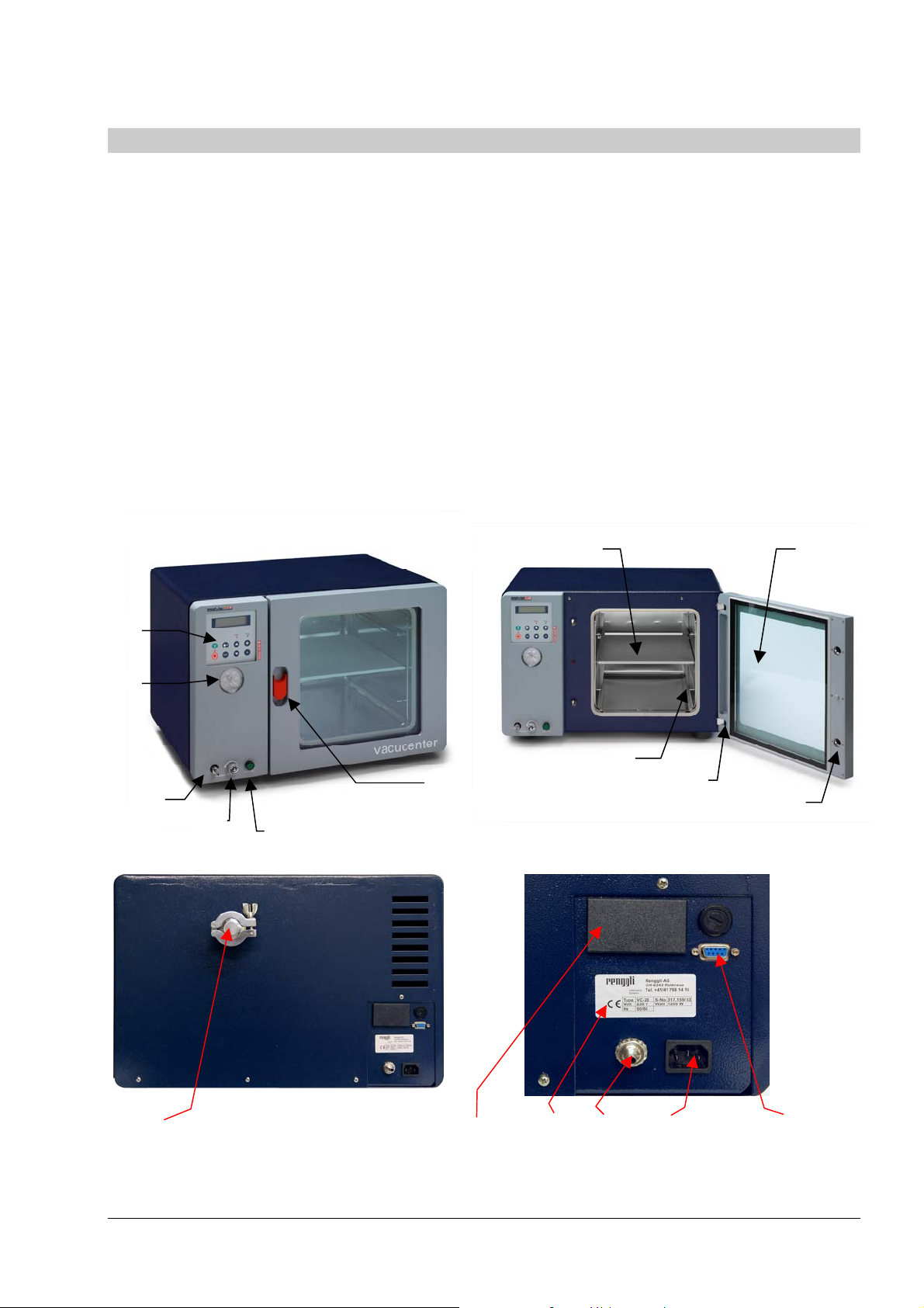
System Components
1 Controller
2 Pressure Gauge
3 Inert Gas / Air Inlet
4 Precision Valve
5 Vacuum Switch
6 Door Handle
7 Shelf
8 Shelf Glider
9 Double Paned Security Glass
10 Spring loaded door lock
11 Spring loaded door hinge
12 Pass through NW 25
13 Serial Interface RS232
14 Power connection
15 Vacuum connection
16 Serial number plate
17 Power connection for vauum pump (only by option
vacuum control of internal valve/vacuum pump)
7
1
2
8
6
11
3
4
12 17 16 15 14 13
5
9
10
- 10 - Copyright © SalvisLab / Edition 191107
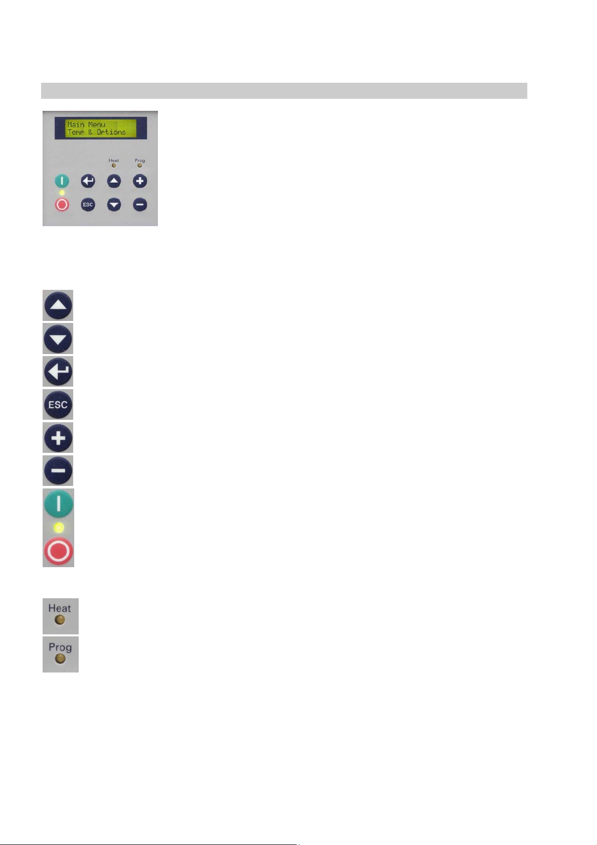
Controller
Keypad & Display
Buttons
S
T
Up You can scroll through the menu structure
Down You can scroll through the menu structure
Enter Confirm a menu selection, Confirm a value input or an answer choice
ESC
+
-
Escape Cancel actual operation, Go back in Menu Structure, Quit actual state ….
Plus
Minus
To control the system the controller has few “easy to use” buttons on a foil
keypad. Simply press desired button.
All information is displayed on a Liquid Crystal Display (LCD) with backlit.
LED Indicators for status of Power, Heating and Program are used to indicate
the main process status.
Buzzer (not visible) is indicating audible Status or Alarm
Increase a value in flashing input fields , Select multiple Choices;
Input Value must flash to make + button operable
Decrease a flashing value, Select multiple Choices;
Input Value must flash to make + button operable
ON/OFF Switch ON or OFF your System. When on LED is lit
LED Indicators
When lit: Heat Power is on
When lit: You are running a program
When flashing: A delayed start for program operation was entered.
Copyright© SalvisLab / Edition 191107 - 11 -

Operating
How to interpret displays described in this manual...
Power ON Sequence
By pressing the power-on button, the display will show the
Salvis Lab
Revision XX.XX
Input Field
software version. All standard, pre-setted or saved information will
be loaded during this process. After a while display will show first
Main Menu Point
Set Temperature
100.1°C
Multiple Input Fields
Set_Start-Date
DDMMYY__17.08.07
Multiple Choice Fields
Display_Interval
Yes___ No
A input value which is underlayed with yellow(grey) background
means this value is flashing on the real display.
If you reach a multiple input display first time, the first part (… of 3
in this example) of the input field is flashing to indicate input here..
Flashing input fields are changed with +/- keys
In a multiple choice field the last actual setted (pre-set) option will
flash. Change option with + or – and confirm with
Definitions of terms
What is a Set Temperature?
A Set Temperature is the target temperature you want operate the system with.
What is a Gradient?
A Gradient is the slope of the heating up process to the specific set temperature.
It is indicated as ºC / Minute. Negative Gradients are not allowed. The maximal value of a gradient is system
depending and has a range and is pre-defined by factory. A system specific curve of gradient corridors see
What is a Set Vacuum / Hysteresis Vacuum (only with Vacuum Controller Option)?
Set Vacuum is the target vacuum value. Hysteresis Vacuum is the vacuum-value range to the set value.
Within this range the valve or pump is not active. This is a P-control behaviour.
What is a Holding Time?
A timer is used to specify how long a set temperature has to be hold. The timer starts counting back when
the set temperature is reached. The maximal time you can set is: 999 hours and 59 minutes. This equals a
max time of 41 days 15 hours and 59 minutes
What is a Start Date/Time
If you are using a start date or time you will be able to set a future date/time to start a process or a program.
- 12 - Copyright © SalvisLab / Edition 191107

Main Menu - Overview
General operation buttons
In general you can scroll through the menu points with the T or S button.
Select the desired menu point with
1 Temperature & Options
Main Menu
Temp & Options
2 Program
Main Menu
Program
3 Configuration
Manual Operation: Define a set temperature and options like
gradient, Vacuum values, Hold-time (dwell-time), programmed
start date/time.
Press to select Ä 1.1
ESC returns to Ä 1
Programmed Operation: The menu Program is divided in
menus for creating, editing, deleting , starting and printing
programs.
Press to select Ä 2.1
ESC returns to Ä 1
Main Menu
Configuration
4 Service Mode
Main Menu
Service Mode
This menu point allows you to configure the system
Press to select Ä 3.1
ESC returns to Ä 1
This menu point is protected by an access-code and is available
only for trained Service-Technicians.
Press to select Ä 4.1
ESC returns to Ä 1
Copyright© SalvisLab / Edition 191107 - 13 -

1 Main Menu - Temp & Options
Manual Operation: Define a set temperature and options like
Main Menu
Temp & Options
1.1 Set Temperature
gradient, Vacuum values, Hold-time (dwell-time), programmed
start date/time.
Press to select Ä 1.1
ESC returns to Ä 1
Set_Temperature_
_________100.1°C
1.2 Set Vacuum
Set Vacuum
_____ 120.6mbar
1.3 Set Hysteresis of vacuum (P-type control behaviour)
Hyster. Vacuum
_____ 2.5mbar
1.4 Select Quick Start or Start with Options
Start_?
Now__ Options
1.5 Set Gradient
Gradient
2.0°C/Min
+/- change desired value.
confirms and saves value Ä 1.2
ESC restores the old value or returns to Ä 1
Option “Vacuum Control” (Valve or Pump) only !
+/- Change value
confirms and saves value Ä 1.3
ESC restores the old value or returns to Ä 1
Option “Vacuum Control” (Valve or Pump) only !
+/- Change value
confirms and saves value Ä 1.4
ESC restores the old value or returns to 1
+/- Select desired answer
confirms and saves value
If Now selected: System will start immediately Ä 6
If Option
ESC cancels and returns to Ä 1
+/- Change value
confirms and saves the value Ä 1.6
ESC restores the old value or returns to Ä 1
Note: A value of 0,0 means maximal possible gradient value!
selected Ä 1.5
- 14 - Copyright © SalvisLab / Edition 191107

1.6 Set Holding Time (dwell time)
Hold Time
HHH:MM____ 15:00
1.7 Set Start-Date
Start Date
DDMMYY__15.05.07
1.8 Set Start Time
Start Time
HH:MM______13:10
+/- Change value
confirm value and skips to the next input field (HH Ä MM) or
stores the time and go to Ä 1.7
ESC restores the old value and skips back one input field
(MMÄHH) or goes back to Ä 1
Note: A value of 0:00 means endless holding time
+/- Change desired value
confirm value and skips to the next input field (DD Ä MM,
MMÄYY) or stores the date and go to Ä 1.8
ESC restores the old value and skips back one input field
(YYÄMM, MMÄ DD) or goes back to Ä 1
Note: The pre-set date is the actual date from the real-time clock.
+/- Change desired value
confirm value and skips to the next input field (HH Ä MM) or
stores the time and go to :
If the Start Date and/or Start Time is in the past, the display will
return back to Ä 1
If your Start Date and/or Start Time is in the future you will see
the operating display Ä 5
ESC restores the old value and skips back one input field
(MMÄHH) or goes back to Ä 2.1
Note: The pre-set time is the actual time from the real-time clock.
Copyright© SalvisLab / Edition 191107 - 15 -
 Loading...