

Salvislab Thermocenter TC40/100
User Manual

Salvislab Thermocenter TC40/100 User Manual
User Manual Salvislab Thermocenter TC40/100
CE DECLARATON OF CONFORMITY ................................................................................................5
1 GENERAL ..................................................................................................................................6
1.1 P
1.2 D
1.3 C
1.4 P
URPOSE OF THIS DOCUMENT
ESCRIPTION
OPYRIGHT
RESENTATION OF SAFETY ADVICE
........................................................................................................................... 6
............................................................................................................................. 6
....................................................................................................... 6
.................................................................................................. 6
2 SAFETY .....................................................................................................................................6
2.1 O
2.2 G
2.3 I
BSERVE SAFETY ADVICE
ENERAL SAFETY ADVICE
NTENDED USE
......................................................................................................................... 6
............................................................................................................. 6
............................................................................................................. 6
3 IMPORTANT INFORMATION ....................................................................................................7
3.1 Q
UICK INFORMATIONS FOR SERVICE
............................................................................................... 7
4 TECHNICAL DATA .....................................................................................................................8
5 INTRODUCTION .......................................................................................................................9
5.1 O
5.2 A
5.3 C
5.4 C
5.5 R
5.6 D
5.7 G
5.8 M
5.9 D
5.10 D
5.11 S
VERVIEW
PPLICATIONS
ONSTRUCTION
ONTROLLER
EGULATION
ISPLAY
ENERAL SETTINGS
ULTI USER LEVELS
ATA CONNECTION
.............................................................................................................................. 9
.......................................................................................................................... 9
........................................................................................................................ 9
........................................................................................................................... 9
......................................................................................................................... 10
............................................................................................................................... 10
................................................................................................................. 10
................................................................................................................. 11
.................................................................................................................. 11
OOR ALARM
AFETY / POWER CUT-OFF
...................................................................................................................... 11
..................................................................................................... 11
6 GETTING STARTED ................................................................................................................ 12
6.1 P
6.2 I
6.3 I
6.4 C
ARTS DELIVERED
NSTALL REQUIREMENTS
NSTALLING
LEANING
................................................................................................................... 12
........................................................................................................................... 12
............................................................................................................................. 12
............................................................................................................ 12
7 SYSTEM COMPONENTS .......................................................................................................... 13
8 OPERATION ........................................................................................................................... 14
8.1 D
EFINITIONS OF TERMS
............................................................................................................ 14
9 SALVISTEQ GRAPHIC USER INTERFACE: FIRST STEPS ........................................................ 15
9.1 S
9.2 M
TARTUP SCREEN
ENU
.................................................................................................................................. 15
.................................................................................................................... 15
10 MANUAL MODE ................................................................................................................... 16
10.1 T
10.2 D
EMPERATURE SETTINGS
EVICE-SPECIFIC SETTING OPTIONS
........................................................................................................ 17
........................................................................................... 18
10.2.1 Fan settings .................................................................................................................. 18
10.3 T
IME SETTINGS
................................................................................................................... 19
10.3.1 Start in ........................................................................................................................ 19
10.3.2 Start at ........................................................................................................................ 20
10.3.3 Hold for ....................................................................................................................... 20
11 PROGRAM MODE ................................................................................................................ 21
11.1 C
11.2 P
REATE NEW PROGRAM
ROGRAM LIST
.................................................................................................................... 22
.......................................................................................................... 21
- 2
Copyright© SalvisLab / Edition 30062016_2.0

Salvislab Thermocenter TC40/100 User Manual
11.2.1 Load program from device ............................................................................................. 23
11.2.2 Save program as ........................................................................................................... 23
11.3 L
11.4 P
11.5 E
OAD A PROGRAM FROM A
ROGRAM OPTIONS
DIT PROGRAM
.............................................................................................................. 23
................................................................................................................... 24
USB
STICK
........................................................................................ 23
11.5.1 Create new program step ............................................................................................... 25
11.5.2 Temperature / general step settings ................................................................................ 26
11.6 S
CHEDULE PROGRAM
............................................................................................................. 26
11.6.1 Daily repetition ............................................................................................................. 27
11.6.2 Weekly repetition .......................................................................................................... 28
11.7 E
11.8 D
XPORT PROGRAM
ELETE PROGRAM
................................................................................................................ 29
................................................................................................................ 30
12 SETTINGS ........................................................................................................................... 31
12.1 I
12.2 L
12.3 U
NFORMATION
ANGUAGE
SERS
..................................................................................................................... 32
......................................................................................................................... 33
.............................................................................................................................. 34
12.3.1 Create user .................................................................................................................. 35
12.3.2 Delete user ................................................................................................................... 35
12.4 L
OCK THE SCREEN
................................................................................................................ 36
12.4.1 Unlock screen ............................................................................................................... 37
12.5 S
12.6 G
CREEN SAVER
ENERAL SETTINGS
.................................................................................................................... 37
.............................................................................................................. 38
12.6.1 System restart process .................................................................................................. 38
12.6.2 Calibration .................................................................................................................... 38
12.6.3 Date and time ............................................................................................................... 39
12.6.4 System log ................................................................................................................... 40
12.6.5 Temperature unit .......................................................................................................... 41
12.6.6 Upper temperature limit ................................................................................................. 41
12.6.7 Lower temperature limit ................................................................................................. 41
12.6.8 Reset ........................................................................................................................... 42
12.6.9 Test ............................................................................................................................. 42
12.6.10 Update ..................................................................................................................... 42
12.6.11 Network settings ........................................................................................................ 43
12.6.12 Buzzer delay .............................................................................................................. 45
12.6.13 Sterilization ............................................................................................................... 45
12.6.14 Product information .................................................................................................... 45
12.6.15 Maximum temperature ............................................................................................... 46
12.6.16 Process log time ........................................................................................................ 46
12.6.17 System error ............................................................................................................. 47
12.6.18 DAC ......................................................................................................................... 48
12.7 L
OGS
............................................................................................................................... 48
13 KEYBOARD ......................................................................................................................... 49
13.1 QWERTZ ......................................................................................................................... 49
13.2 N
13.3 S
UMERIC
........................................................................................................................... 49
PECIAL INPUT ERRORS
.......................................................................................................... 50
13.3.1 Input using number keys ............................................................................................... 50
13.3.2 Keyboard input ............................................................................................................. 51
14 USB ..................................................................................................................................... 52
14.1 E
XPORT/IMPORT WITH
USB-S
TICK
........................................................................................... 52
15 ETHERNET .......................................................................................................................... 52
16 ADMIN FEATURES .............................................................................................................. 53
16.1 SW U
PDATE
....................................................................................................................... 53
16.1.1 Unlock options .............................................................................................................. 54
16.2 T
EST SCREEN
...................................................................................................................... 54
- 3
Copyright© SalvisLab / Edition 30062016_2.0

Salvislab Thermocenter TC40/100 User Manual
APPENDIX A ................................................................................................................................. 55
G
RAPHS OF TEMPERATURE LIMITS, GRADIENT AND PROGRAM RUN
.................................................................... 55
Temperature limiter & safety controlling ....................................................................................... 55
Range of allowable heating gradients ........................................................................................... 56
Graphical presentation of a program run ....................................................................................... 56
APPENDIX B ................................................................................................................................. 58
W
IRING DIAGRAM
TC40/100 .............................................................................................................. 58
APPENDIX C ................................................................................................................................. 59
S
ALVIS
TEQ RU
PRINTED BOARD
........................................................................................................... 59
APPENDIX D................................................................................................................................. 60
S
ALVIS
TEQ DU
PRINTED BOARD
........................................................................................................... 60
APPENDIX E ................................................................................................................................. 61
L
EGEND
......................................................................................................................................... 61
APPENDIX F ................................................................................................................................. 62
D
RAWING SALVISLAB THERMOCENTER
TC40 ............................................................................................. 62
APPENDIX G ................................................................................................................................. 63
D
RAWING SALVISLAB THERMOCENTER
TC100 ........................................................................................... 63
APPENDIX H ................................................................................................................................ 64
D
RAWING SPARE PARTS
TC40 .............................................................................................................. 64
APPENDIX I ................................................................................................................................. 65
D
RAWING SPARE PARTS
TC100 ............................................................................................................ 65
APPENDIX J ................................................................................................................................. 66
D
RAWING SPARE PARTS PANEL
TC40/100 ............................................................................................... 66
APPENDIX K ................................................................................................................................. 67
S
PARE PARTS AND OPTIONALS
............................................................................................................... 67
GLOSSARY ................................................................................................................................... 69
- 4
Copyright© SalvisLab / Edition 30062016_2.0

Salvislab Thermocenter TC40/100 User Manual
CE DECLARATON OF CONFORMITY
Declaration of Conformity
Wir
We
Nous
erklären in alleiniger Verantwortung, dass das Produkt
declare under our sole responsibility that the product
déclarons sous notre seule responsabilité que le produit
Drying Oven TC40/100
Year of Construction 2015
(Bezeichnung Typ oder Modell, Los-, Chargen- oder Seriennummer, möglichst Herkunft und Stückzahl)
(name, type or model, lot, batch or serial number, possibly sources and numbers of items)
(nom, type ou modèle, no de lot, d'échantillon ou de série, éventuellement sources et nombre d’exemplaires)
auf das sich diese Erklärung bezieht, mit der/den folgenden Norm(en) oder normativen Dokument(en)
übereinstimmt
to which this declaration relates is in conformity with the following standard(s) or other normative
document(s)
auquel se réfère cette déclaration est conforme à la (aux) norme(s) ou autre(s) document(s)
normatif(s)
(Titel und/oder Nummer sowie Ausgabedatum der Norm(en) oder der anderen normativen (Dokumente)
(title and/or number and date of issue of the standard(s) or other normative document(s)
(titre et/ou no et date de publication de la (des) norme(s) ou autre(s) document(s) normatif(s)
Gemäss den Bestimmungen der Richtlinien; following the provisions of directives; conformément aux
dispositions des directives; (falls zutreffend) (if applicable) (le cas échéant)
Safety EN 61010-1:2001 Safety EN 61010-2:2003
Low voltage directive 2006/95/EC EMC directive 2004/108/EC
(Ort und Datum der Ausstellung) (Name/Unterschrift oder Kennzeichnung des Befugten)
(Place and date of issue) (name and signature or equivalent marking of authorised person)
(Lieu et date) (nom et signature du signataire autorisé)
Renggli AG / SalvisLab
(Name des Anbieters) (supplier's name) (nom du fournisseur)
Birkenstrasse 31, CH-6343 Rotkreuz
(Anschrift) (address) (adresse)
Alain Frenguelli
Rotkreuz · CH, 31.10.2015 Alain Frenguelli
Technical Manager
- 5
Copyright© SalvisLab / Edition 30062016_2.0
Salvislab Thermocenter TC40/100 User Manual
!
i
1 General
1.1 Purpose of this document
This document describes the use of the newly developed warming cabinets and control regulation unit of
Renggli AG /Salvislab. Observation of the operating instructions can ensure safe, proper and economical use
of the device.
This manual contains information relevant to end customers. This document is not to be provided to
!
third parties without the permission of Renggli AG/Salvislab
1.2 Description
Warming cabinets are used for tempering of laboratory samples or other items in medical and general
laboratory environments.
1.3 Copyright
The copyright of this composition and all documents entrusted to the customer remains at all time with
Renggli AG/Salvislab. This document must not be provided to third parties or made available without the
written permission of Renggli AG.
1.4 Presentation of safety advice
The following symbols indicate safety tips and other general information:
Indicates a danger that may lead to physical injury or to irreversible loss of data.
Indicates additional information and tips.
2 Safety
2.1 Observe safety advice
Read all safety advice in this document carefully as well as all warning signs attached to the device. Pay
attention to the legibility of the warning signs and replace them immediately when they become damaged.
2.2 General safety advice
Check the device for operation safety before each use.
2.3 Intended use
Thermocenter units are not built to be used as ovens for drying substances which are explosive or release
explosive gases during the drying process. Any use other than the one the units are intended for is
forbidden.
The warming cabinet controller is built with state of the art technology and satisfies all recognized safety
regulations. Use this device only in the manner described in this manual. No guarantee can be made with
regard to the properties and safety of the device in the event of improper use.
- 6
Copyright© SalvisLab / Edition 30062016_2.0
Salvislab Thermocenter TC40/100 User Manual
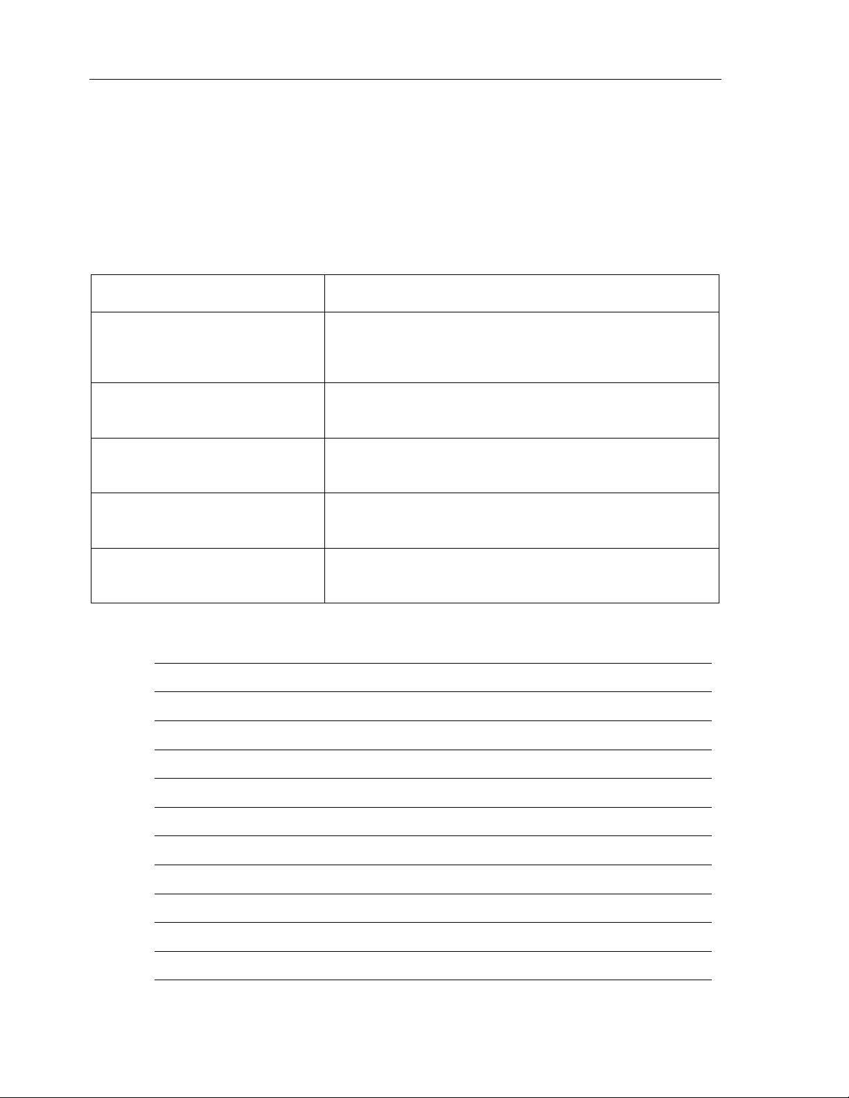
3 Important information
3.1 Quick Informations for Service
Dear customer,
Thank you for purchasing our Salvislab Thermocenter drying oven.
Please fill out all the necessary information of your Thermocenter in the form below and keep it ready in
case you will need to contact for assistance your Dealer or Service department.
SERIAL NUMBER
TYPE OF OVEN
SERVICE PHONE NUMBER
PURCHASE DATE
SOFTWARE VERSION
(Settings Menu_Informations)
FIRMWARE VERSION
(Settings Menu_Informations)
Notes:
TC40
TC100
- 7
Copyright© SalvisLab / Edition 30062016_2.0
Salvislab Thermocenter TC40/100 User Manual
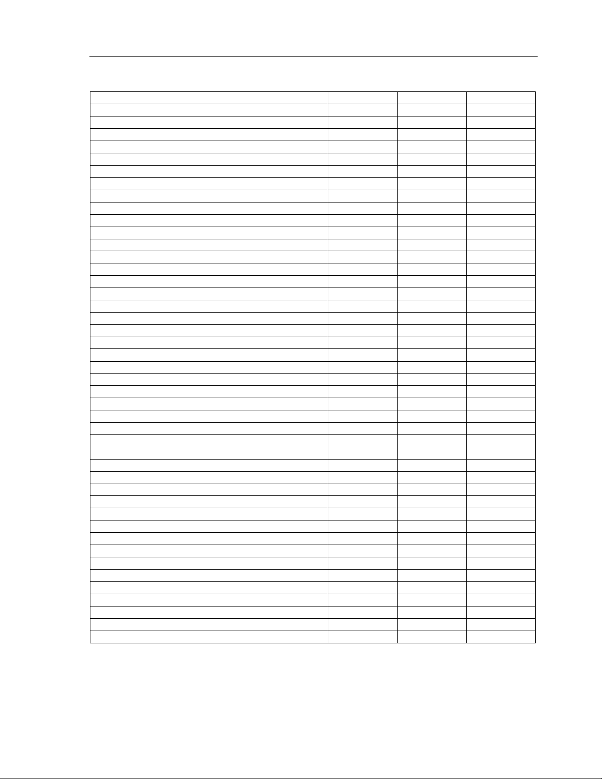
4 Technical data
[unit] TC40 TC100
Outer Dimension
Width mm 460 570
Height mm 507 620
Depth mm 525 656
Clearance distance from back wall mm 100 100
Clearance distance from side wall mm 100 100
Inner Dimension
Width mm 340 450
Height mm 370 500
Depth mm 328 456
Internal Volume L 40 100
Shelf standard/max 1/8 1/8
Shelf dimension (WxD) mm 295x324 437x425
Distance between shelf mm 35 50
Max. load per shelf kg 20 20
Max. load per oven kg 40 50
Weight oven (empty) kg 30 50
Temperature range approx. 5°C > Tr to °C 200 200
Temperature deviation
Temperature deviation
Temperature deviation
Temperature fluctuation
Heating up time
to 150°C min 24 35
to 200°C min 34 45
Recovering time after 30 sec door opening 3) at 100°C min 4 7
Air changes (exhaust flap open) at 100°C x/h 59 29
Power supply (±10%) 50/60 Hz Volt 115/230 115/230
Nominal Wattage Watt 1100 1100
Energy consumption at 100°C Watt 145 230
at 150°C Watt 300 544
Recommended ambient values T °C 15 - 25 15 - 25
Equipment
SalvisTEQ controller with predictive regulation - Yes Yes
Capacitive touch display inches/pixels 5.7”/640x480 5.7”/640x480
Linear/logarithmic heating gradient - Yes Yes
Adjustable fan speed % 60 - 100 60 - 100
Multi user levels - Yes Yes
Program mode programs/steps 99/99 99/99
USB host interface for data import/export - Yes Yes
Ethernet port - Yes Yes
Preselectable restart procedure in case of power failure - Yes Yes
Timer and counter hours/min 0-999/59 0-999/59
1) Measured with 3 temperature probes on horizontal level / divided in 1/3 of the chamber size
2) maximum temperature deviation in time for one temperature probe
3) to 98% of set temperature
All technical specification are specified for units with standard equipment at an ambient temperature of 25 °C (77 °F) and a voltage fluctuation of ±10 %. The
temperature data are determinated in accordance to following DIN 12880, part 2 respecting the recommended wall clearances of 10 % of the height, width and
depth of the inner chamber. All indications are average values, typical for units produced in series. Differing ambient temperatures or variances in the design of
individual equipment may produce different performance. We reserve the right to alter technical specifications at all times without prior notice.
*We reserve the right to alter technical specifications at any time without prior notice.
1)
at 50°C ± °C 0.4 0.4
1)
at 100°C ± °C 1.0 1.0
1)
at 150°C ± °C 1.5 1.7
2)
3)
at 150°C ± °C 0.2 0.2
to 70°C min 10 15
ϕ % 20 - 60 20 - 60
- 8
Copyright© SalvisLab / Edition 30062016_2.0

Salvislab Thermocenter TC40/100 User Manual
5 Introduction
5.1 Overview
•
The THERMOCENTER TC40/100 is an oven with a patented design
•
Robust “SwissTEQ” quality design
•
Thermocenter ovens ensure effective drying without damaging the material being dried
•
All functional elements are integrated in the door
•
High grade stainless steel chamber
•
Standard unit provided with one aluminium shelf
•
Chamber has rounded edges which allows easy cleaning
•
Minimized heat losses due to low thermal conductivity insulation
•
Exterior textured powder coated steel
•
SalvisTEQ controller with dynamic regulation and improved efficiency
•
Forced Air with an intelligent control of fan speed in a range between 60 and 100%
•
Capacitive touch display, intuitive and user-friendly
•
Multiple user levels
•
Drag&drop user lock function
5.2 Applications
•
The Thermocenter line is designed for all purposes of drying in a variety of laboratory fields
•
Controller with capacitive touch display and unlimited programming capabilities
•
A must when precise temperature distribution and a high accuracy are needed
•
Temperature range up to + 200°C/392°F
•
It can be used for research & development, quality control as well as for a wide range of industrial and
laboratory applications
•
Examples of usage: color fastness test for textiles, ageing test for plastics and foils, quality control of
electronic circuits, food analysis, dry sterilization in hospitals
5.3 Construction
•
Due to extremely compact all-in-door construction the Thermocenter saves valuable space in lab
•
Electro-polished stainless steel inner chamber, chemical resistant and highly durable
•
All edges rounded for easy cleaning and maintenance
•
Maximized shelves area (in comparison to inner volume): up to 8 shelves
•
Door seal easily removable for cleaning or replacing
•
Door handle fully integrated in the door
•
No hot surfaces
5.4 Controller
•
SalvisTEQ controller with dynamic regulation
•
The regulation unit controls the heating with a predictive regulation
•
Multi-point temperature calibration (up to 10 points)
•
Self identification of heating gradient
•
Real time clock with process times
•
Calendar-settable programs start (date/time)
•
Hold time (process-end shown as date/time): 0 - 999h 59m
•
Enhanced program mode (up to 99 programs and 99 steps per program)
•
Scheduler
•
Programs remain stored in memory even without external power
•
Import/export of programs over USB - optional: LAN
•
Real time visualization of current program´s process data
•
Export process data over USB - optional: LAN
•
Preselect restart procedure in case of power failure
•
Interal DU memory expandable via micro SD card up to 32GB - optional
•
Log of process data for 300.000 entries (approx. 400 hours at a sampling rate of 5s)
- 9
Copyright© SalvisLab / Edition 30062016_2.0

Salvislab Thermocenter TC40/100 User Manual
•
Log of system data for the last 50.000 events
•
Adjustable log interval
•
Export Log-data over USB - optional: LAN
•
Hardware and software self-test
•
Reset to factory settings
•
Base commands in remote access mode under Java Script Object Notation (JSON) - optional
•
Software updates/upgrades over USB - optional: LAN
•
User identification with USB-dongle - optional
•
Import process-diagrams over USB - optional: LAN
5.5 Regulation
•
The regulation unit works on a STM32 microcontroller
•
The regulation unit controls the heater with a predictive controller
•
Settable heating gradient (linear or logarithmic)
•
Separate temperature guard (Class 3.3 according to DIN 12880)
•
Select input for target temperature
•
Communication between regulation and display unit works with SPI bus
•
Error handling
•
PT100 interface has 4 wires-circuit
•
Internal system voltage
5.6 Display
•
Capacitive touch Display 5.7”
•
Resolution of 640x480 pixels
•
Landscape format
•
User friendly and intuitive graphic user interface
•
Graphic accelerator
•
Internal system voltages
•
Display regulation unit works with a microcontroller ARM Cortex A8 Processor
•
Storage of persistent parameters and log files
•
Display includes a protective glass cover
5.7 General Settings
•
Selectable Temperature units: °C or °F
•
Adjustable time and time zone
•
Adjustable date
•
Available menu languages: EN, GE, IT, FR, ES - optional: CN
•
Acoustic alarms for key tones, program end and errors
•
Acoustic alarm for door open with adjustable delay (default 30s)
•
User administration (user ID) protected by password
•
Dynamic IP address
•
Counter for operating hours - optional
- 10
Copyright© SalvisLab / Edition 30062016_2.0

Salvislab Thermocenter TC40/100 User Manual
5.8 Multi user levels
This new feature allows more than one user on a single device by separating their accounts, application data
and access rights.
User* It is the lowest user level. This user level allows to run the unit, define custom
programs, set date and time, temperature measurement unit, restart procedure,
process data sampling time, check for unit errors and access to the basic informations
of the unit.
Calibrator* The Calibrator level includes the user level capabilities and integrates the unit
calibration.
Administrator** The Administrator level includes the User level capabilities. In addition it allows to
perform tests on the critical components of the unit, update software, access to the
system log, reset the user’s database and run a sterilization program. It also
guarantees the ability to modify some key working parameters of the unit such as
upper and lower deviation, DHCP, max adjustable temperature and buzzer delay. It
provides User administration rights.
Service*** It is the highest level. This access is granted only to qualified factory technicians for
service and upgrades.
5.9 Data connection
•
USB 2.0 Port
•
LAN-Port, RJ45 10/100 Mbit - optional
5.10 Door alarm
•
The door is monitored by a mechanical switch
•
It is not possible to start a manual process when the door is open; the message “door open” will appear
on the display
•
The heating process is interrupted when the door is opened during a manual process (heating off), as
soon the door is closed the heating process will start again (heating on)
5.11 Safety / Power Cut-Off
•
Independent temperature safety device class 3.3 according to DIN 12880:
+
Integrated digital under- and over-temperature protection which automatically follows the
set point value at a preset tolerance range, and switches the heating off in case of over- or under
temperature deviations
+
A built in safety controller takes over if the first protection is in state of error and shuts the oven
down in case of over-temperature
+
A mechanical over-temperature device provides additional safety
•
After power cut-off controller restarts automatically and last stored values remain in memory
•
High quality accurate PT100 temperature probes
•
Integrated door switch interrupts heater when opening the door
- 11
Copyright© SalvisLab / Edition 30062016_2.0
Salvislab Thermocenter TC40/100 User Manual
6 Getting started
6.1 Parts delivered
Your System will be delivered with the following parts:
•
1 Thermocenter unit
•
1 Shelf
•
1 Power cord
6.2 Install requirements
• For your safety be sure your oven is installed properly by a qualified installer or service technician
• This appliance must be supplied with the proper voltage and frequency. See rating plate located on the
back of the oven frame to determine the rating of the product
• Leave at least 10 cm space between system and walls or benches
• Max. 1 Thermocenter can be stuck on top (for stacking adapter see options list)
• If you install a ducting to exhaust system then please contact your dealer for more information
6.3 Installing
•
Place shelf in appropriate position
•
Plug in the power cable
•
Close the door
•
Switch power on
•
Display shows Salvislab logo during boot
•
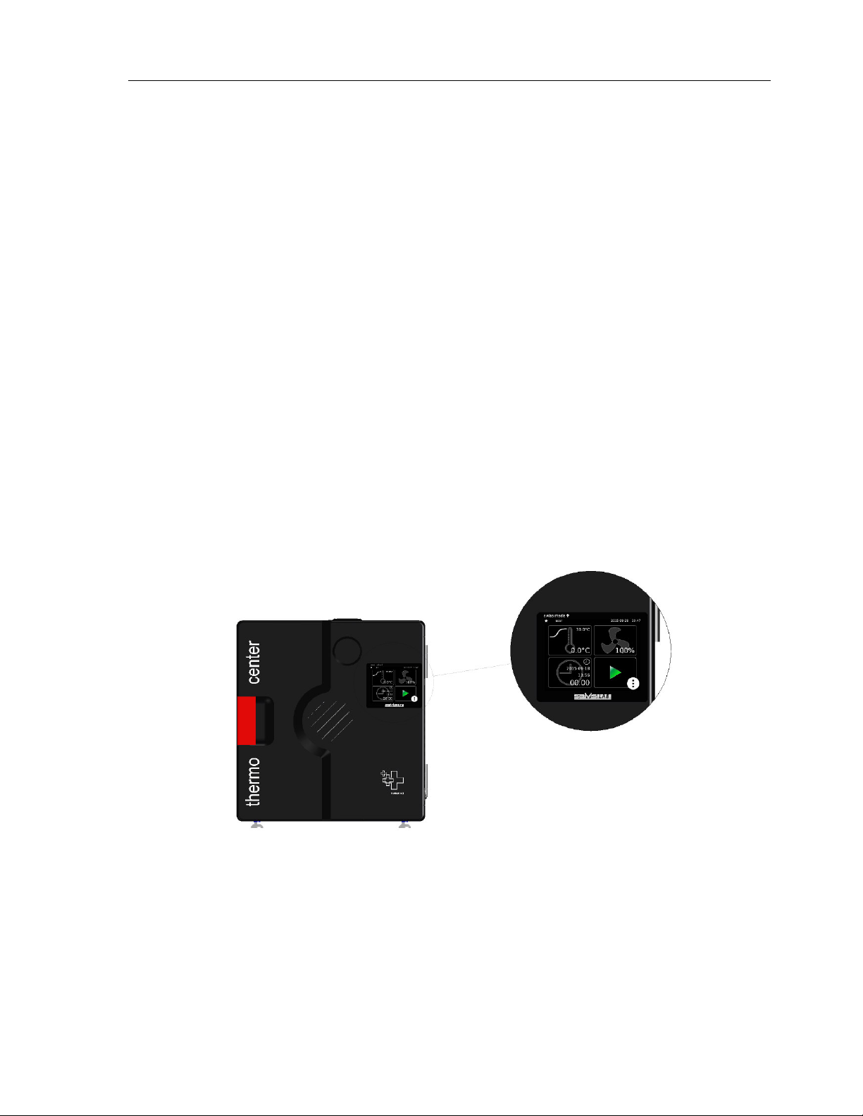
The device is ready for use when the SalvisTEQ Home menu appears on screen
•
For information on how to operate and navigate properly through the GUI, refer to chapters 9-16
SalvisTEQ Home Menu
6.4 Cleaning
•
Use mild detergents for cleaning oven surfaces (no acid/alcohol based or similar detergents)
•
Use microfiber cloths for cleaning the display
•
Never use abrasive cloths, paper towels, or tissue paper, which can scratch the touchscreen. If any
water at all is necessary, power off your device ahead of time
•
Never press too hard while cleaning the screen. This can damage the display
- 12
Copyright© SalvisLab / Edition 30062016_2.0
Salvislab Thermocenter TC40/100 User Manual
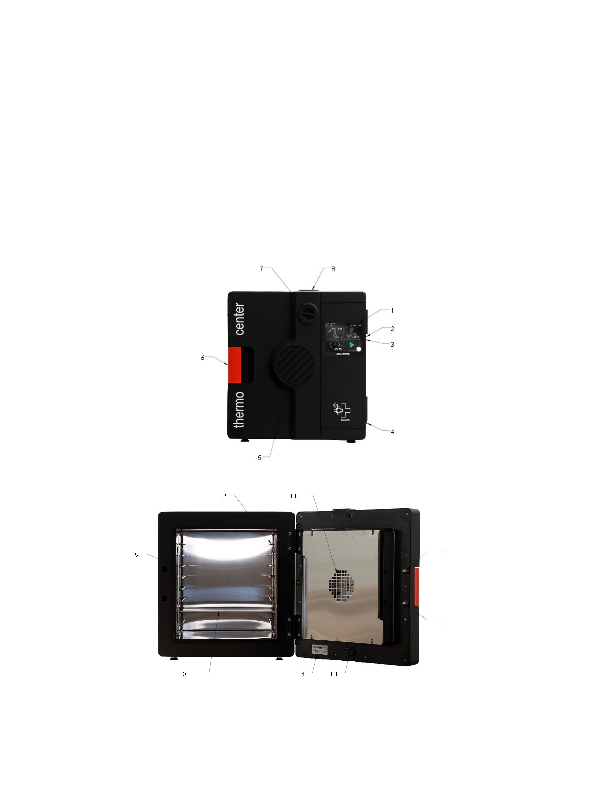
7 System Components
1 SalvisTEQ touch display
2 USB Port
3 LAN Port
4 Main on/off switch
5 Air inlet
6 Door handle
7 Air flap
8 Air exhaust
9 Shelf support
10 Shelf
11 Fan outlet
12 Spring loaded door lock
13 Door switch
14 Rating plate
Thermocenter front view - closed door
Thermocenter front view - open door
- 13
Copyright© SalvisLab / Edition 30062016_2.0

Salvislab Thermocenter TC40/100 User Manual
8 Operation
8.1 Definitions of terms
Set temperature
•
“Target” temperature oven should operate with
Gradient
•
Slope of heating up process to specific set temperature (indicated in ºC/min or °F/min)
•
Negative gradients not allowed
•
Maximal value of gradient depends on system and has a range which is predefined by manufacturer
Hold time
•
Duration a set temperature has to be hold (build-in timer is starting to count back as soon as set
temperature is reached)
•
Maximal set time is 999 hours and 59 minutes
Start date / time
•
Future date/time to start process or program
- 14
Copyright© SalvisLab / Edition 30062016_2.0
Salvislab Thermocenter TC40/100 User Manual
1
2
3
4
9 SalvisTEQ Graphic user interface: First steps
Ensure that the device is in a mechanically sound state before connecting the power. Connect the power
cable. Turn on the device using the main power switch on the side of the device.
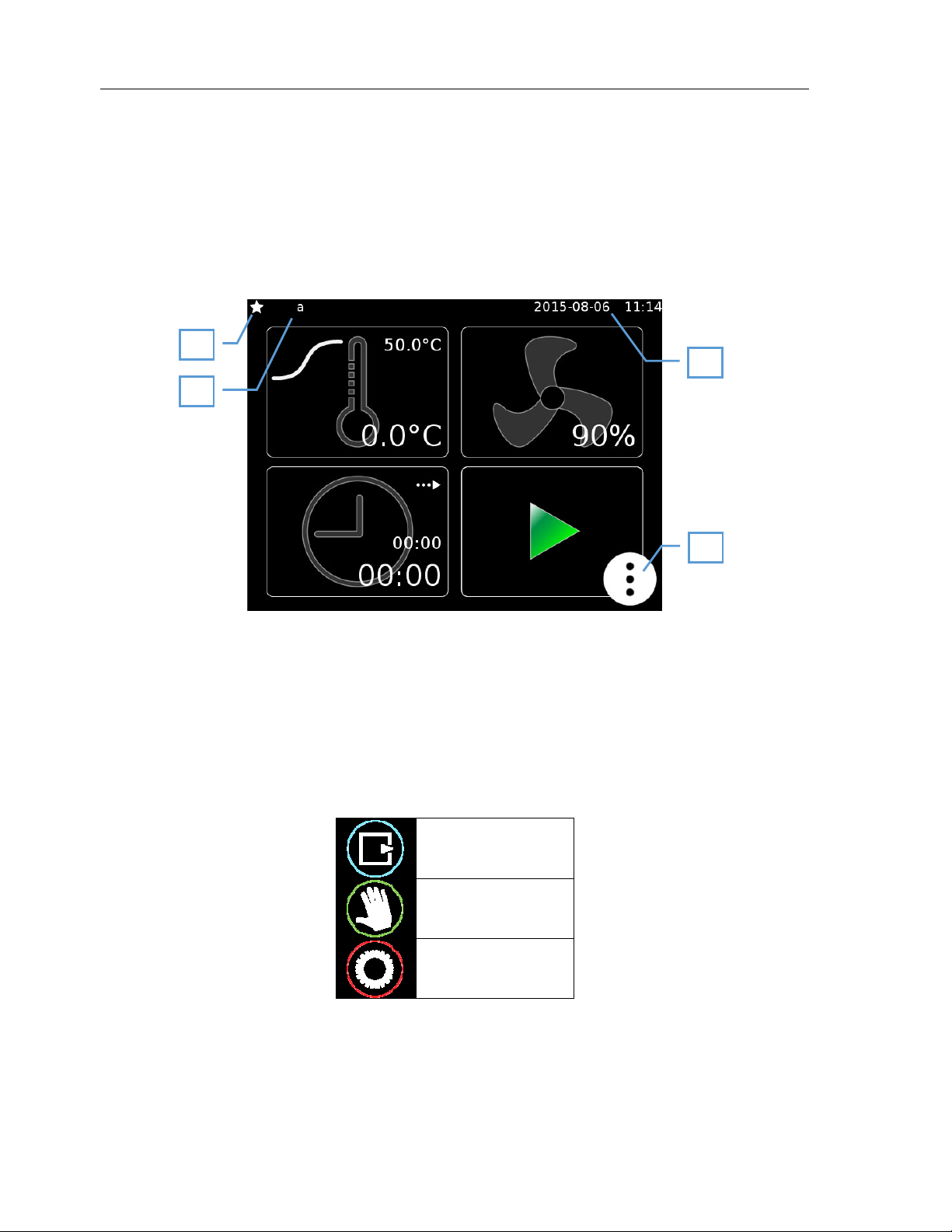
9.1 Startup screen
The device starts in manual mode. The settings available in this mode are described in chapter 10.
Program mode is described in chapter 11.
1 User level
2 Logged on users
3 Date and time display
4 Open menu
9.2 Menu
Pressing the tool button [4] opens the device menu.
Program mode (11)
Manual mode (10)
Settings (12)
- 15
Copyright© SalvisLab / Edition 30062016_2.0
Salvislab Thermocenter TC40/100 User Manual
1
3
4
2
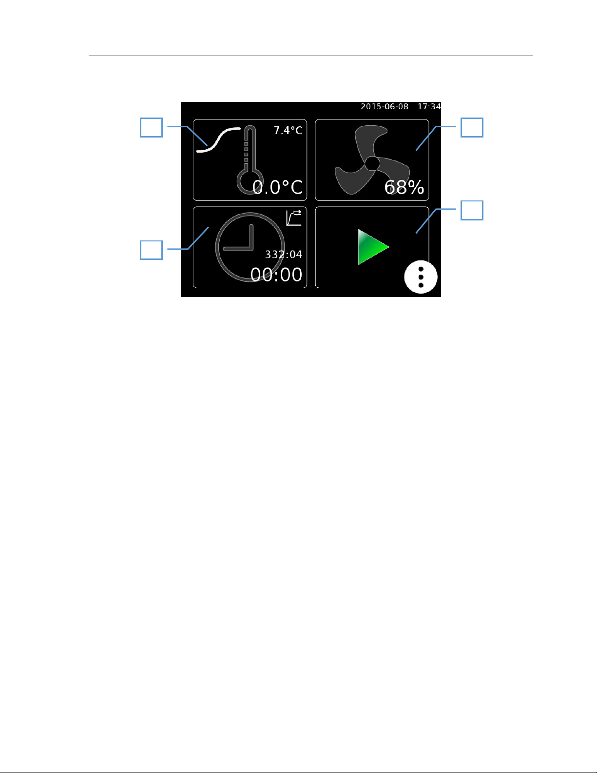
10 Manual mode
1 Temperature settings (10.1)
2 Device-specific settings (10.2)
3 Time settings (10.3)
4 Play button, starts the warming process using the selected settings.
- 16
Copyright© SalvisLab / Edition 30062016_2.0
Salvislab Thermocenter TC40/100 User Manual
1
5
4
3
2
6
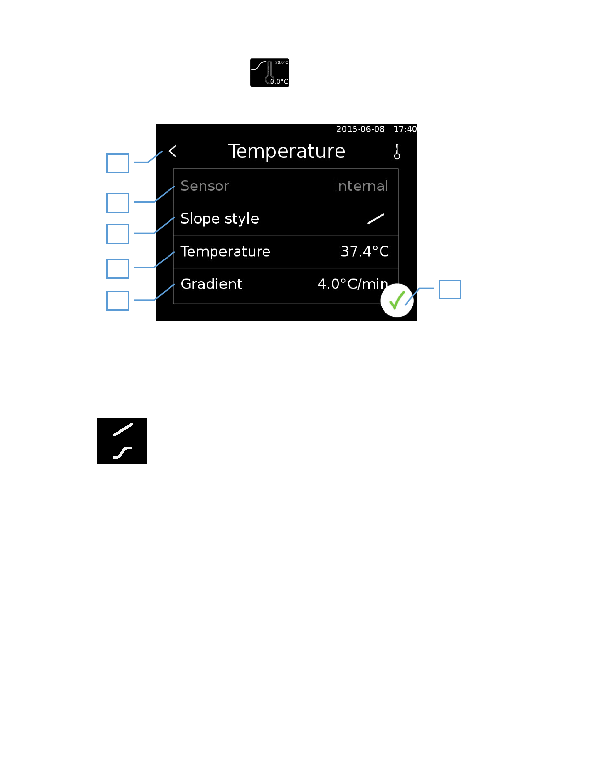
10.1 Temperature settings
This menu contains all settings in relation to the internal temperature of the device.
1 Back to main screen
2
3 Select the type of heating curve.
4 Target temperature
5 Gradient (for linear heating processes only)
6 Confirm input
Sensor selection for temperature measurement.
Internal: the internal sensor is located inside the device.
External: the external sensor is inserted into a port on the device and can be placed at the
point where the set temperature should be reached (optional).
Linear heating using the set gradients
Exponential heating, the target temperature is approached with the largest
possible gradient.
- 17
Copyright© SalvisLab / Edition 30062016_2.0
Salvislab Thermocenter TC40/100 User Manual
1
2
3
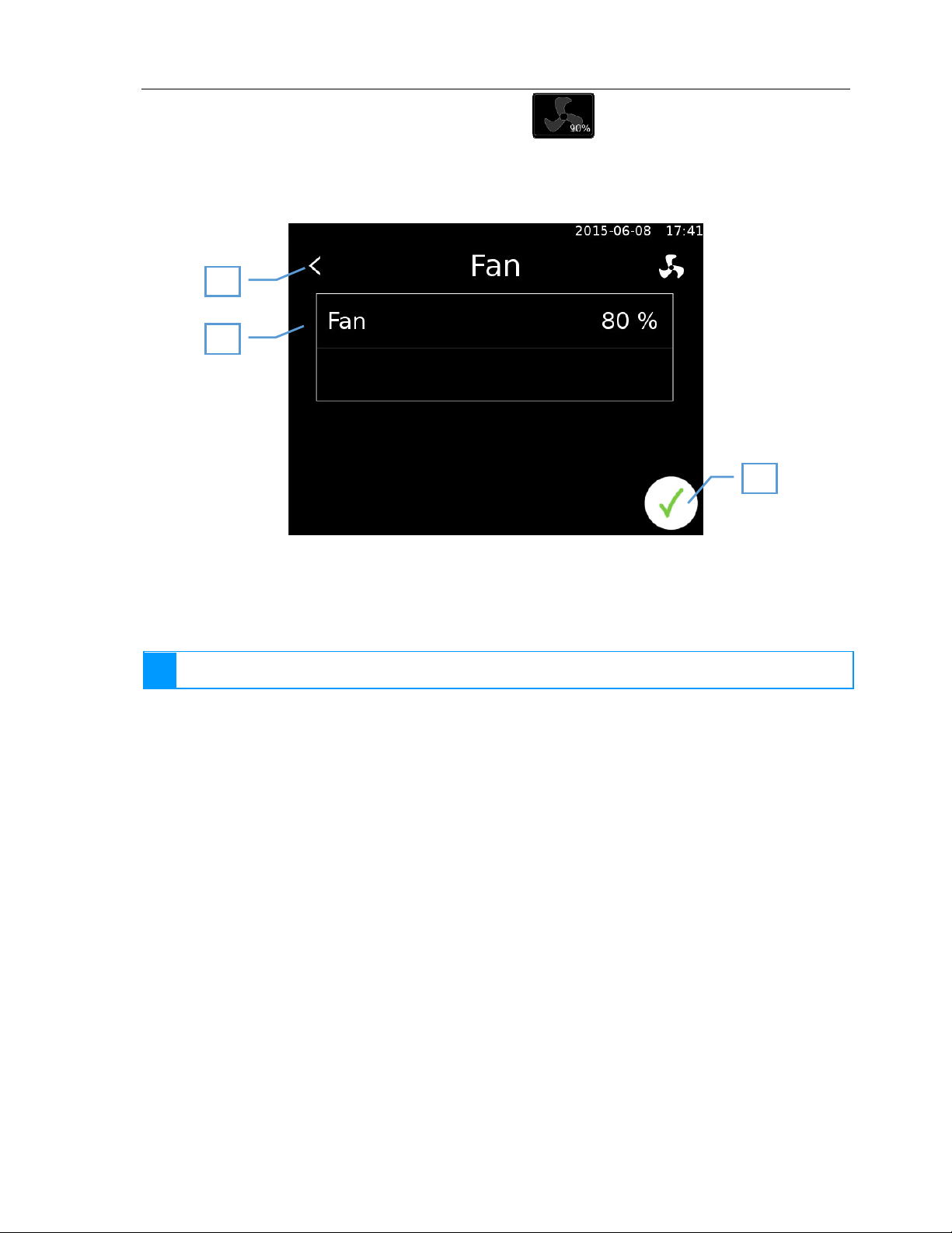
10.2 Device-specific setting options
10.2.1 Fan settings
This menu provides options for controlling the fan.
1 Back
2 Fan rotation speed. The fan speed can be set between 60 - 100%.
3 Confirm input
The fan is always required to ensure even internal heating. The speed can therefore be reduced, but
i
the fan cannot be turned off completely.
- 18
Copyright© SalvisLab / Edition 30062016_2.0
Salvislab Thermocenter TC40/100 User Manual
i
1
2
3
4
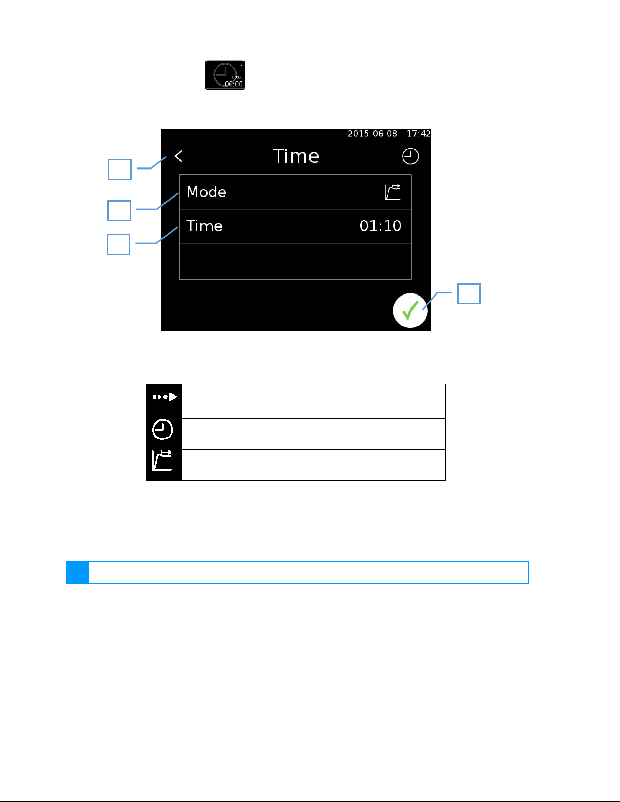
10.3 Time settings
The time menu provides options for configuring start and stop times.
1 Back to main screen
2 Select start mode
Start in: Start delay (10.3.1)
Start at: Start at specified time (10.3.2)
Hold for: Heat up and hold for specified time (10.3.3)
3 Time settings, dependent on selected mode
4 Confirm input
10.3.1 Start in
Start of the heating process is delayed by the set time.
A time of 000:00 indicates an immediate start.
- 19
Copyright© SalvisLab / Edition 30062016_2.0
Salvislab Thermocenter TC40/100 User Manual
1
2
1
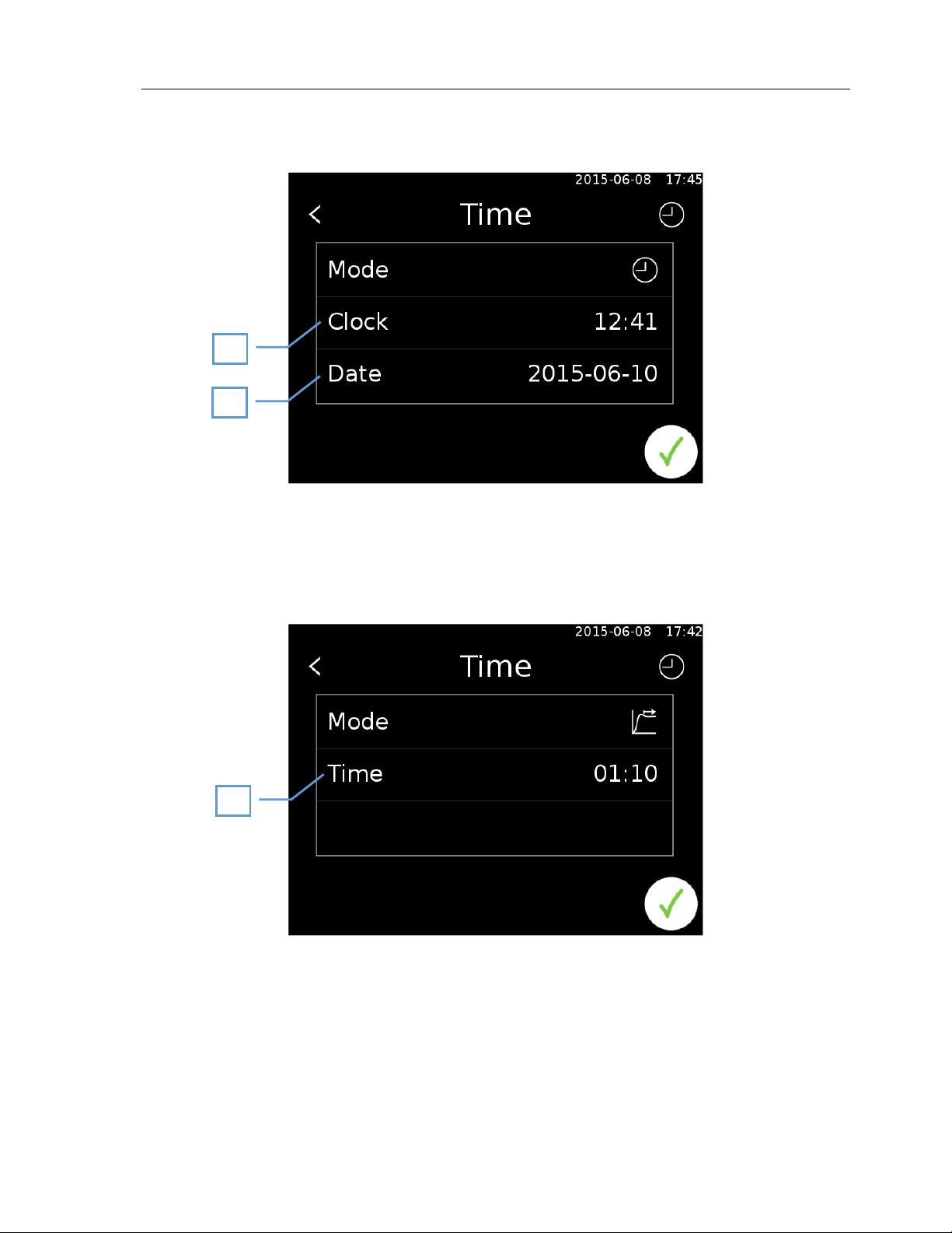
10.3.2 Start at
The date and time to start the process is selected.
1 Time
2 Date
10.3.3 Hold for
Hold the target temperature for a specific length of time. The hold time begins once the target temperature
has been reached.
1 Time for which the target temperature should be held.
- 20
Copyright© SalvisLab / Edition 30062016_2.0
Salvislab Thermocenter TC40/100 User Manual
i
1
2
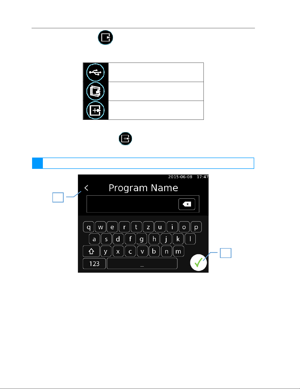
11 Program mode
If the user presses the program mode symbol in the menu, then the second level of the menu opens. This
provides the user with the following menu options:
Load a program from a USB stick (11.3)
Program list (11.2)
Create new program (11.1)
Existing programs can be modified once they have been loaded (11.5).
11.1 Create new program
To create a new program you first need to enter a name for it.
The name you enter cannot be changed later.
1 Back to main screen
2 Confirm input
- 21
Copyright© SalvisLab / Edition 30062016_2.0

Salvislab Thermocenter TC40/100 User Manual
1
2
2
1
3
4
After the name has been confirmed, the user is asked to create the first program step.
1 Edit / create program (11.5)
2 Menu
11.2 Program list
This screen contains a list of all existing programs on the device.
1 Back
2 Program list
3 Save program as (11.2.2)
4 Load program from device (11.2.1)
- 22
Copyright© SalvisLab / Edition 30062016_2.0

Salvislab Thermocenter TC40/100 User Manual
1
2
3
4
6
5
11.2.1 Load program from device
Open the selected program for editing or other actions.
11.2.2 Save program as
The selected program will be stored on the device with a new name. Therefor the keyboard (13.1) appears.
11.3 Load a program from a USB stick
If you have programs on a USB stick, then it is possible to load these onto the device. Insert the USB stick in
to the device and select "Load from USB" from the menu.
11.4 Program options
An overview of the program is displayed once it has been loaded. Several actions are available.
1 Program name
2 Start
3 Terminate (11.6)
4 Edit (11.5)
5 Export (11.7)
6 Delete (11.8)
- 23
Copyright© SalvisLab / Edition 30062016_2.0

Salvislab Thermocenter TC40/100 User Manual
1
3
4
5
8
7
9
2
6
11.5 Edit program
1 Current program step
2 Temperature / general step settings (11.5.2)
3 Fan settings (10.2.1)
4 Previous program step
5 Insert new program step before current step (11.5.1)
6 Delete program step
7 Next program step
8 Insert new program step after current step (11.5.1)
9 Finish editing
- 24
Copyright© SalvisLab / Edition 30062016_2.0

Salvislab Thermocenter TC40/100 User Manual
Symbol
Mode
Description
11.5.1 Create new program step
The user can choose between four different step types. Touching the symbols on the screen switches
through the different program steps. The following table describes the four program steps.
Fast
Linear The set temperature is approached linearly
Hold
Repeat The program jumps to a selected program step
The set temperature will be reached as quickly as
possible
The current temperature is held for a set period of
time
- 25
Copyright© SalvisLab / Edition 30062016_2.0

Salvislab Thermocenter TC40/100 User Manual
Symbol
Settings
1
2
3
4
11.5.2 Temperature / general step settings
Setting options for individual steps vary depending on the type of the step.
Temperature: The user selects the desired target temperature.
Temperature: The user selects the desired target temperature.
Gradient: Specifies the temperature change per minute.
Time:
Jump to: The step to which the program should jump.
Repeat:
How long to hold the temperature from the previous program
step.
How often should this step be repeated when reaching this
program step.
11.6 Schedule program
A selected program can be terminated. The user has the option of setting a program to start at a defined
date and time.
Programs can also be set to be regularly repeated. Only one individual program can be scheduled.
1 Back
2 Program name
3 Repetition type
+
Daily (11.6.1)
+
Weekly (11.6.2)
+
Never (no repetition)
4 Confirm input
- 26
Copyright© SalvisLab / Edition 30062016_2.0

Salvislab Thermocenter TC40/100 User Manual
1
2
1
2
If a specific time is set for the program to run then the scheduler is automatically started.
1 Execution time display
2 Cancel scheduler
11.6.1 Daily repetition
1 Execution time
2 Confirm input
- 27
Copyright© SalvisLab / Edition 30062016_2.0

Salvislab Thermocenter TC40/100 User Manual
1
2
3
11.6.2 Weekly repetition
1 Execution time
2 Selected weekday (11.6.2.1)
3 Confirm input
11.6.2.1 Select day
The corresponding buttons are used to the select the desired days for the program to be started.
- 28
Copyright© SalvisLab / Edition 30062016_2.0

Salvislab Thermocenter TC40/100 User Manual
2
3
1
11.7 Export program
The selected program can be exported to a USB stick. A program can only be exported after a USB stick has
been inserted into the device.
1 Back
2 Export target
3 Export
You are informed via an information bar after the program has been successfully exported or if an error
occurred during the export process.
- 29
Copyright© SalvisLab / Edition 30062016_2.0

Salvislab Thermocenter TC40/100 User Manual
1
2
11.8 Delete program
The loaded program can be deleted from the device. This action must then be confirmed.
1 Back
2 Confirm deletion
- 30
Copyright© SalvisLab / Edition 30062016_2.0

Salvislab Thermocenter TC40/100 User Manual
12 Settings
Information (12.1)
Language (12.2)
Users (12.3)
General settings (12.6)
Logging (12.7)
- 31
Copyright© SalvisLab / Edition 30062016_2.0

Salvislab Thermocenter TC40/100 User Manual
8
9
1
2
3
4
5
6
7
12.1 Information
All important product information as well as the address of the manufacturer are displayed in an information
window. The info screen also contains a QR code that can be scanned to directly access the manufacturer's
website.
1 Back
2 Device type
3 Serial number
4 RU serial number
5 DU serial number
6 Control unit software version
7 Regulator firmware version
8 Manufacturer address
9 QR code, contains link to manufacturer´s website
- 32
Copyright© SalvisLab / Edition 30062016_2.0

Salvislab Thermocenter TC40/100 User Manual
12.2 Language
The user can select the interface language by pressing on the flag for the desired language.
The language setting is applied after pressing the OK button.
- 33
Copyright© SalvisLab / Edition 30062016_2.0

Salvislab Thermocenter TC40/100 User Manual
2
1
3
4
5
6
7
12.3 Users
An administrator must be logged on to access this menu. Additional users can then be created.
Each user needs a user name, a password and an access permission type. The administrator can create
additional administrators as well as users.
The user level is indicated using stars:
User
Calibrator
Administrator
Service technician
1 Back
2 Username
3 User level
4 Log out
5 Create new user (12.3.1)
6 Delete user (12.3.2)
7 Confirm input
Copyright© SalvisLab / Edition 30062016_2.0
- 34

Salvislab Thermocenter TC40/100 User Manual
2
3
4
1
5
4
1
2
3
12.3.1 Create user
1 Back
2 Enter username
3 Enter password
4 Select role
5 Confirm input
12.3.2 Delete user
1 Back
2 User list (select a user by clicking)
3 Delete selected user
4 Back
- 35
Copyright© SalvisLab / Edition 30062016_2.0

Salvislab Thermocenter TC40/100 User Manual
1
2
3
4
5
6
12.4 Lock the screen
If the user administration option is enabled, then the currently running process can be locked by a user. This
requires the user to first log in. Once the user is logged in, they can start the oven or program in manual
mode. A small lock now appears on the display. The screen can now be locked by using your finger to drag
the lock into the circle that appears on screen.
1 User is logged on
2 Start heating process
3 Open lock appears
4 Drag lock
5 Circle appears
6 Drag lock into circle, the oven is
now locked
- 36
Copyright© SalvisLab / Edition 30062016_2.0

Salvislab Thermocenter TC40/100 User Manual
12.4.1 Unlock screen
To unlock the screen it is necessary to drag the closed lock again. As soon as you start dragging the lock, a
circle appears. Dragging the lock into the circle brings up the login screen. The operator who originally
locked the oven needs to log in again here in order to unlock it.
The screen can be unlocked at any time by an administrator or service technician. Other users
i
cannot unlock the oven.
12.5 Screen saver
A screensaver appears after 30 minutes of standby time. This screen will only be activated, if no regulation is
in progress. Touch the display on any position to deactivate the screensaver and return to the last screen.
- 37
Copyright© SalvisLab / Edition 30062016_2.0

Salvislab Thermocenter TC40/100 User Manual
4
1
2
3
12.6 General settings
1 Back
2 List of options
3 Scroll
4 Back
12.6.1 System restart process
This option controls the behavior of the system when restarted. Depending on the settings, the process
being worked on beforehand will be:
• stopped
• resumed
• newly restarted
12.6.2 Calibration
The internal and external temperature sensors can be calibrated with the help of this menu.
Calibration is secured using a password or can be done only by the service technician.
i
For more detailed information, please contact the manufacturer.
- 38
Copyright© SalvisLab / Edition 30062016_2.0

Salvislab Thermocenter TC40/100 User Manual
2
1
1
3
3
4
2
12.6.3 Date and time
1 Back
2 Set date
3 Set time
4 Confirm input
12.6.3.1 Set date
1 Back
2 Select date
3 Confirm input
- 39
Copyright© SalvisLab / Edition 30062016_2.0

Salvislab Thermocenter TC40/100 User Manual
1
1
6
6
2
3
5
4
12.6.4 System log
The system log can be viewed here. All important events are logged by the controller here and displayed.
The controller deletes the oldest file after a certain period of time. If you want to permanently save
!
the log data, then you will need to do a regular export operation.
You can swipe up and down to scroll through the system log.
1 Back
2 List of log files
3 Open log
4 Export log
5 Delete log
6 Back
- 40
Copyright© SalvisLab / Edition 30062016_2.0

Salvislab Thermocenter TC40/100 User Manual
12.6.5 Temperature unit
The temperature unit can be switched between Celsius and Fahrenheit.
The unit only becomes active when pressing the confirm button upon closing the general settings
!
menu.
12.6.6 Upper temperature limit
The upper temperature limit can be set between 2 and 20 degrees Celsius. If the target temperature for the
oven is set above this limit then the safety regulator is activated.
When regulating using the external sensor, the oven temperature is monitored with this value. Errors
!
may occur if the limit is too narrowly set.
The limits do not define the precision of the regulator. They define only when the safety regulator is
i
activated.
12.6.7 Lower temperature limit
The lower temperature limit can be set between 2 and 20 degrees Celsius. If the target temperature in the
oven drops lower than the set temperature then the safety regulator is turned on.
When regulating using the external sensor, the oven temperature is monitored with this value. Errors
!
may occur if the limit is too narrowly set.
The limits do not define the precision of the regulator. They define only when the safety regulator is
i
activated.
- 41
Copyright© SalvisLab / Edition 30062016_2.0

Salvislab Thermocenter TC40/100 User Manual
!
12.6.8 Reset
Administrative users are able to reset the database.
This will delete all current parameters, programs and users.
12.6.9 Test
The test screen allows all sensors and actuators to be monitored and tested. The test screen is explained in
more detail in chapter 16.2.
12.6.10 Update
The user can run a software update from here. The new software first needs to be loaded onto a USB stick.
This is then inserted into the device. For further detail please refer to chapter 16.1.
- 42
Copyright© SalvisLab / Edition 30062016_2.0

Salvislab Thermocenter TC40/100 User Manual
1
2
3
4
5
12.6.11 Network settings
This menu item allows the network address to be set. The IP address is automatically assigned by default,
whereby the controller is automatically assigned an IP address by the network. This can be manually set
using "static" mode.
12.6.11.1 Automatic
1 Back
2 Mode (change by clicking)
3 Current address (assigned by the network)
4 Current subnet mask (assign by the network)
5 Confirm input
- 43
Copyright© SalvisLab / Edition 30062016_2.0

Salvislab Thermocenter TC40/100 User Manual
1
2
3
4
5
6
12.6.11.2 Manual
1 Back
2 Mode (change by clicking)
3 Set address
4 Set subnet mask
5 Set gateway
6 Confirm input
It can take a little time for the IP address to be assigned, as the controller must first check whether
i
the set address is already in use on the network before setting the new address.
- 44
Copyright© SalvisLab / Edition 30062016_2.0

Salvislab Thermocenter TC40/100 User Manual
1
2
3
4
5
6
7
12.6.12 Buzzer delay
A warning buzzer will sound, if the door is opened whilst a process is running. The delay before the buzzer
sounds can be set between 30s and 5 minutes.
12.6.13 Sterilization
The oven can be sterilized using the sterilization option. This raises the temperature to 180°C and holds it at
this temperature for 30 minutes in accordance with WHO guidelines. Devices that can reach a maximum of
160°C are held at this temperature for 180 minutes.
If the sterilization procedure is interrupted, then it is considered as invalid. This is saved in the oven.
Successful sterilization is recorded with the date and time in the oven in order to show that the last
successful sterilization was run.
12.6.14 Product information
This menu option brings up the oven settings.
12.6.14.1 Oven data
1 Back
2 Oven type
3 Maximum temperature (operational)
4 Minimum temperature (operational)
5 Maximum temperature (calibration)
6 Scroll
7 Back
Copyright© SalvisLab / Edition 30062016_2.0
- 45

Salvislab Thermocenter TC40/100 User Manual
i
1
2
3
12.6.14.2 Options
1 Back
2 Options (sensors, actuators)
3 Scroll
12.6.15 Maximum temperature
This menu option allows the temperature to be limited. The maximum temperature is fixed by the oven, but
depending on the requirements of the process that the oven is being used for, can be lowered.
Please check all of your programs (if any) after setting the temperature. Existing programs are not
!
automatically adjusted.
12.6.16 Process log time
This allows you to set the interval for logging process data. The value can be set between 2s and 5min.
Longer sample times allow process data to be recorded over longer periods.
- 46
Copyright© SalvisLab / Edition 30062016_2.0

Salvislab Thermocenter TC40/100 User Manual
1
1
4
3
2
12.6.17 System error
This menu displays system errors which have appeared.
12.6.17.1 Appearance of an error
If an error appears, a red bar will show information error information.
The system error screen appears if the red bar is touched.
1 Information about the occurred error
12.6.17.2 System error screen
This screen can be accessed by clicking on an error popup bar or in the general settings window.
1 Back
2 Acknowledge the marked error
3 List of appeared errors
4 Scroll
If you acknowledge an error who is gone, it will be automatically deleted from the list. If the error
i
condition is still met, the error will reappear.
- 47
Copyright© SalvisLab / Edition 30062016_2.0

Salvislab Thermocenter TC40/100 User Manual
i
i
5
1
2
3
4
12.6.17.3 Alarm contact
The potential free contact is used for the alarm contact. This contact is closed in an error-free condition. If
an error appears, the contact is opened. The contact will stay open as long as the user acknowledges all
errors in the list.
This feature is only available with the corresponding option.
12.6.18 DAC
The device has two analogue outputs. They can be mapped to the system sensors.
The following options are possible:
Sensor Formula
Temperature internal Voltage [V] = temperature [°C] * 30 +1V
Temperature external Voltage [V] = temperature [°C] * 30 +1V
Temperature ambient Voltage [V] = temperature [°C] * 30 +1V
Fan speed Voltage [V] = fan speed [%] / 10
Only available with the corresponding option.
12.7 Logs
Users have the option to export or delete logged process data.
1 Back
2 List of process logs
3 Delete selected process data
4 Export selected process data
5 Back
- 48
Copyright© SalvisLab / Edition 30062016_2.0

Salvislab Thermocenter TC40/100 User Manual
4
1
2
3
4
1
2
3
13 Keyboard
The keyboard can be switched between text (QWERTZ) and number input.
13.1 QWERTZ
1 Back
2 Switch to numeric keyboard
3 Delete last character
4 Confirm input
13.2 Numeric
1 Back
2 Delete last character
3 Switch to QWERTZ keyboard
4 Confirm input
- 49
Copyright© SalvisLab / Edition 30062016_2.0

Salvislab Thermocenter TC40/100 User Manual
1
2
4
3
8
7
6
5
13.3 Special input errors
All settings such as temperature, fan speed, etc. are set in their corresponding screen using a unified user
interface.
The respective maximum and minimum values cannot be exceeded.
13.3.1 Input using number keys
1 Back
2 Increase the respective digit
3 Clicking on a number opens up the keyboard input (13.3.2)
4 Lower the respective digit
5 Name of the value to set
6 Decimal point, position varies depending on value/value range
7 Unit
8 Confirm input
- 50
Copyright© SalvisLab / Edition 30062016_2.0

Salvislab Thermocenter TC40/100 User Manual
1
4
3
2
13.3.2 Keyboard input
This input method allows the value to be entered directly.
Input uses a fixed decimal point location. This means, for example, to set a temperature of 120°C, you need
to press [1], [2], [0], [0].
1 Back
2 Name of the value to set
3 Delete last digit
4 Confirm input
If an invalid value is entered, then the user is prompted to enter a valid value.
- 51
Copyright© SalvisLab / Edition 30062016_2.0

Salvislab Thermocenter TC40/100 User Manual
i
14 USB
14.1 Export/Import with USB-Stick
The controller allows data to be exported to and imported from a USB stick. It is necessary for the USB to be
detected by the controller for this to be done.
The controller determines for itself if a USB stick is available. A message is provided on an information bar if
a suitable stick is detected:
It is possible that not all USB sticks will be recognized by the controller. Please contact the
i
manufacturer to determine a suitable type.
15 Ethernet
The current status of the device can be called up over the Ethernet interface. A TCP/IP connection with the
following properties is created for this:
Port: 1234
IP: IP address of the device
More detailed information can be found in document [Host Interface Specification].
- 52
Copyright© SalvisLab / Edition 30062016_2.0

Salvislab Thermocenter TC40/100 User Manual
i
!
!
1
2
3
16 Admin features
The features described in this chapter can only be used with the admin user. For further informations
!
please contact your dealer.
16.1 SW Update
1 Back
2 List of which software version and firmware is installed.
3 Check for updates
Insert USB stick to continue
It is possible that not all USB sticks will be recognized by the controller. Please contact the
i
manufacturer to determine a suitable type.
Clicking on the button [3] searches the USB stick for the appropriate files. This may take a moment. The file
can then be selected and the update starts.
The pre-set file name of the update may not be changed on the computer.
An update may take several minutes. The controller will restart during the update. Please ensure to
!
follow all instructions on the screen and never turn off the device.
Only remove the USB stick once the update has completed and the device has restarted.
- 53
Copyright© SalvisLab / Edition 30062016_2.0

Salvislab Thermocenter TC40/100 User Manual
!
!
16.1.1 Unlock options
Options can be installed via the software update. The corresponding file needs to be saved on the USB and
selected and to do this.
The pre-set file name of the update may not be changed on the computer.
An update may take several minutes. The controller will restart during the update. Please ensure to
!
follow all instruction on the screen and never turn off the device.
Only remove the USB stick once the update has completed and the device has restarted.
16.2 Test screen
The test screen allows all features and sensors of the device to be checked.
- 54
Copyright© SalvisLab / Edition 30062016_2.0

Salvislab Thermocenter TC40/100 User Manual
Appendix A
Graphs of temperature limits, gradient and program run
Temperature limiter & safety controlling
Thermal levels of a Thermocenter unit.
ID Color ID Param.
1 TB Mechanical temperature limiter 260
2 TWB Electronical temperature limiter ≤200
3 Tsp Set point temperature (Tr - TWB]
4 T
5 T
Electronical over-temperature protection [Tsp ; Tsp+10]
WW, max
Electronical under-temperature protection [Tsp-10 ; Tsp]
WW, min
Description
Typ. value
[°C]
- 55
Copyright© SalvisLab / Edition 30062016_2.0

Salvislab Thermocenter TC40/100 User Manual
Range of allowable heating gradients
1. Lower gradient range. No working points allowed
2. Gradient can be set in this range
3. Upper gradient range. No working points allowed
Graphical presentation of a program run
This example shows a custom user program defined in the custom programs section with 4 steps and a preset calendar start date/time. For further detail please refer to chapter 11 “Program mode”.
- 56
Copyright© SalvisLab / Edition 30062016_2.0

Salvislab Thermocenter TC40/100 User Manual
0 Timeframe of the start date/time
1 Step 1: start of custom program
2 Step 2: new parameters setting where used
3 Step 3: new parameters setting where used
4 Step 4: repeat step 2 with auto-adjusted parameters setting (after end of step 4 program ends)
Program step 0 can be set through calendar. Program steps 1-3 can be set up in relation to the following
parameters: Set temperature, gradient, hold time. Program step 4 repeats program step 2.
The program steps 1-4 contain respectively:
A Positive gradient (adjustable)
1
B Hold time (adjustable)
C Positive gradient (adjustable)
2
D Hold time (adjustable)
E Positive gradient (adjustable)
3
F Hold time (adjustable)
G Negative gradient (given)
4
H Hold time (according to program step 2)
- 57
Copyright© SalvisLab / Edition 30062016_2.0

Salvislab Thermocenter TC40/100 User Manual
Appendix B
Wiring diagram TC40/100
ID Description
PI Power inlet
S Device main switch (power on/off)
PE Protective earthing
OMF Over-temperature melting fuse
H Heating element
PF Potential free contact
DS Door switch
FA Fan
AO Analog output
I1 PT100 temperature probe
I2 Redundant PT100 temperature probe
EX External connector
Standard device wiring up
- - - - - - Optional device wiring up
Wiring diagram Salvislab Thermocenter TC40/100
- 58
Copyright© SalvisLab / Edition 30062016_2.0

Salvislab Thermocenter TC40/100 User Manual
Appendix C
SalvisTEQ RU printed board
ID Description
D9 Power indicator
D10 Command processing
F1 Main fuse 115/230V = T10AL 250V AC
F2 24V Power supply protection T2AL 250V AC
F3 Sensors / 24V T2AL 250V AC
J1 Connection to display unit
J3 PT100 temperature probe
J4 Connection for pressure transducer
J5 Redundant PT100 temperature probe
J7 Connection for door switch
J8 Vacuum valve
J9 External connector
J11 Connection for ventilation valve
J14 External connector, analogue output
J15 Potential free contact
J16 Connection for main switch
P1 Connection for heating, fan
Q1 Power stage heater
Q4 Power stage fan
U1 Voltage converter
U4 Hardware controller/microprocessor
RU Printed board - 2D layout
RU Printed board - 3D view
Copyright© SalvisLab / Edition 30062016_2.0
- 59

Salvislab Thermocenter TC40/100 User Manual
Appendix D
SalvisTEQ DU printed board
ID Description
P2 Connection to regulation unit
J2 Power supply
B1 Battery 3V 225 mAh
P1 SD card slot
J1 Display connection
J3 Power supply
P3 USB Port
J5 Ethernet Port
P4 USB extension
J6 LAN extension
DU Printed board - 2D Layout
DU Printed board - 3D view
- 60
Copyright© SalvisLab / Edition 30062016_2.0

Salvislab Thermocenter TC40/100 User Manual
Appendix E
Legend
Wiring diagram
main elements
PE Protective earthing x
OMF Over-temperature melting fuse x
H Heating element x
PF Potential free contact x
DS Door switch x
FA Fan x
AO Analog output o
I1 PT100 temperature probe x
I2 Redundant PT100 temperature probe o
EX External connector o
RU Main
outputs
F1 Main fuse 115/230V = T10AL 250V AC - F2 24V Power supply protection T2AL 250V AC - F3 Sensors / 24V T2AL 250V AC - J1 Connection to display unit - J3 PT100 temperature probe - J4 Connection for pressure transducer - J5 Redundant PT100 temperature probe - J7 Connection for door switch - J8 Vacuum valve - J9 External connector - J11 Connection for ventilation valve - J14 External connector, analogue output - J15 Potential free contact - J16 Connection for main switch - P1 Connection for heating, fan - Q1 Power stage heater - Q4 Power stage fan - U1 Voltage converter - U4 Hardware controller/microprocessor - -
DU Main
outputs
ID Description Standard Optional
PI Power inlet x
S Device main switch (power on/off) x
ID Description Standard Optional
D9 Power indicator - -
D10
ID Description Standard Optional
P2 Connection to regulation unit - -
J2 Power supply - B1 Battery 3V 225 mAh - P1 SD card slot - -
J1 Display connection - -
J3 Power supply - P3 USB Port - -
J5 Ethernet Port - P4 USB extension - -
J6 LAN extension - -
Command processing (on while command is
executed)
- 61
- -
Copyright© SalvisLab / Edition 30062016_2.0

Salvislab Thermocenter TC40/100 User Manual
Appendix F
Drawing Salvislab Thermocenter TC40
* Renggli AG / SalvisLab reserves the right to change technical specifications and dimensions without prior notice.
- 62
Copyright© SalvisLab / Edition 30062016_2.0

Salvislab Thermocenter TC40/100 User Manual
Appendix G
Drawing Salvislab Thermocenter TC100
* Renggli AG / SalvisLab reserves the right to change technical specifications and dimensions without prior notice.
- 63
Copyright© SalvisLab / Edition 30062016_2.0

Salvislab Thermocenter TC40/100 User Manual
Appendix H
Drawing spare parts TC40
- 64
Copyright© SalvisLab / Edition 30062016_2.0

Salvislab Thermocenter TC40/100 User Manual
Appendix I
Drawing spare parts TC100
- 65
Copyright© SalvisLab / Edition 30062016_2.0

Salvislab Thermocenter TC40/100 User Manual
Appendix J
Drawing spare parts panel TC40/100
- 66
Copyright© SalvisLab / Edition 30062016_2.0

Salvislab Thermocenter TC40/100 User Manual
Appendix K
Spare parts and optionals
Position Part number Description Standard Optional
1 31W04810075 Panel complete TC40/100 x
2 31W04144182 PCB RU SalvisTEQ x
3 31W04144189 PCB RU - PCB DU cable x
4 31W04142008 Air inlet protection cover x
5 31W04144013 Power cable clamp x
6 31W04144022 Exhaust turning knob x
7 31W04144014 Door handle x
31W04141031 Door complete TC40 115V x
8
9 31W04144015 Locking bolt spring x
10 31W04144016 Locking bolt x
11 31W04144017 Exhaust U-insulation x
12
13 31W04144026 Mounting strap heating element x
14 31W04960700 Door switch x
15 31W04144128 PT100 temperature sensor 4-wires circuit x
16
17 31W04144002 Door hinge x
18 31W04144009 Heating element insulation x
19 31W04962509 Over-temperature melting fuse x
20
31W04141030 Door complete TC40 230V x
31W04141025 Door complete TC100 115V x
31W04141024 Door complete TC100 230V x
31W04143019 Fan 230V x
31W04143053 Fan 115V x
31W04140002 Door inner case TC40 x
31W04140000 Door inner case TC100 x
31W04144110 Heating element 115V x
31W04144012 Heating element 230V x
21
22
23 31W04144184 Display SalvisTEQ x
24 31W04141006 Panel TC40/100 x
25 31W04144183 PCB DU SalvisTEQ x
31W04143107 Air ventilation plate TC40 x
31W04143108 Air ventilation plate TC100 x
31W04943203 Door gasket TC40 1.5m x
31W04943203 Door gasket TC100 2.0m x
- 67
Copyright© SalvisLab / Edition 30062016_2.0

Salvislab Thermocenter TC40/100 User Manual
Position Part number Description Standard Optional
26 31W04144185 PCB DU - Display cable x
27 31W04142015 Main switch x
28 31F04008 Wire shelf TC40 x(1) o
29 31F04010 Wire shelf TC100 x(1) o
30 31F04005 Shelf stainless steel TC40 o
31 31F04006 Shelf stainless steel TC100 o
32 31F04007 Shelf perforated, stainless steel, TC40 o
33 31F04009 Shelf perforated, stainless steel, TC100 o
34 31F04029 Stacking adapter o
35 31F04020 Wall bracket o
36 31F04030 Fresh air filter o
37 31F04015 Exhaust air adapter TC40 o
38 31F04016 Exhaust air adapter TC100 o
39 31F04700 Program and user software upgrade o
40 31F04701 Process graph software upgrade o
41 31F04702
42 31F04703
Product temperature controller software upgrade
and interface
Product temperature probe PT100 with special
connector
o
o
43 31F04706 LAN interface software upgrade o
44 31F04707 Redundant PT100 temperature probe o
45 31F04713 Analog output programmable o
46 31F04717 Potential free contact o
47 31F04025 Entry port 20mm o
48 31F04026 Entry port 40mm o
49 31F04714 Internal memory upgrade up to 32 GB (micro SD) o
50 31F04715
51 31F04716
Calibration certificate for one desired temperature
and point (1st certificate)
Additional calibration certificate for one desired
temperature and point (2nd to 10th certificate)
o
o
52 31F04750 IQ/OQ draft paper, 3 hard copies o
- 68
Copyright© SalvisLab / Edition 30062016_2.0

Salvislab Thermocenter TC40/100 User Manual
Glossary
ID Variable
Description Unit Typ. value
1 ϕ Relative humidity % 40-60
2 TB Mechanical temperature limit °C 260
3 Tr Standard room temperature °C 25
3 Tsp Set point Temperature °C (Tr - TWB]
4 TWB Electronical temperature limit °C ≤200
5 T
6 T
Electronical over-temperature limit °C [Tsp ; Tsp+10]
WW, max
Electronical under-temperature limit °C [Tsp-10 ; Tsp]
WW, min
- 69
Copyright© SalvisLab / Edition 30062016_2.0

Renggli AG / Salvislab
Industrie-Ost
CH-6343 Rotkreuz
Switzerland
T +41 (0)41 798 14 14
F +41 (0)41 798 14 40
www.salvislab.com
salvislab@renggli.com
 Loading...