


SALVIS Combi‐Steamer
623 611 1011 T
611 621 1011 1021 QT
2011 2021 QT
CUCINAr Easy
r
CUCINA
Pro
Installation instructions

Table of contents page
1. User information 3.............................................................
1.1 Information about the instructions for the appliance 3..........................
1.2 Symbols in front of the text 3...............................................
1.3 Warning signs, danger symbols and information symbols 3.....................
1.4 Documenting the type plate data 4..........................................
2. Safety instructions 4...........................................................
3. Transport, Setup 5.............................................................
3.1 Inspection for transport damages 5..........................................
3.2 Transport 5..............................................................
3.3 Setup 5..................................................................
3.3.1 Observe the setup regulations 5.............................................
3.3.2 Choosing the setup location 6...............................................
3.3.3 Maintain clearances 6......................................................
3.3.4 Setup on tables and support structures 7.....................................
3.3.6 Setup of the upright appliances, e.g. Type 2011 8..............................
3.3.7 Installing the compensation frame for Type 2011/2021 (option) 8.................
3.3.8 Apply the safety sticker ”Max. shelf level for liquid cooking products” 9............
4. Water connection 9............................................................
4.1 Information for water connection 9...........................................
4.2 Choice of water softening device / water filter / water treatment 10................
4.2.1 Water treatment systems 10.................................................
4.2.2 Do not use these systems. 10................................................
4.2.3 Water hardness conversion table by country 10.................................
4.2.4 Requirements on the soft‐ and cold‐water connection 11.........................
4.3 Connection of soft‐ and cold water 12.........................................
5. Connecting water drainage – connection examples 13............................
6. Electrical connection 14........................................................
6.1 Connection to an energy optimisation unit (option) 15...........................
6.2 Connection to a load shedding unit 15........................................
7. Initial commissioning 15........................................................
8. Dimensions, connections, technical data 16......................................
8.1 Dimensions and connections 623T, 611T, 1011T 16..........................
2 / 24
8.2 Dimensions and connections 611/621QT, 1011/1021QT 17....................
8.3 Dimensions and connections 2011/2021QT 18................................
8.4 Technical data: 623T, 611T, 1011T 19......................................
8.5 Technical data: 611/621QT, 1011/1021QT 19................................
8.6 Technical data: 2011/2021QT 20............................................
8.7 Technical specifications condensation cover (optional) 20.......................

Translation of the original installation instructions
1. User information
1.1 Information about the instructions for the appliance
These installation instructions contain technical data, information on transport, setup, installation and ad
justment of the appliance. Hand the installation instructions to the installing assemblers. Make sure that
during the installation of the appliance the installation instructions are followed meticulously. This will pro
tect you and prevent damages to your appliance.
Refer to the operating instructions for information about operating the appliance.
Read the operating‐ and installation instructions carefully before starting to use the appliance.
The owner of the appliance must ensure that the instructions are accessible to the staff employed to oper
ate the appliance.
Always keep the documents accompanying the appliance close to hand and pass these on with the appli
ance to any new owner.
Installation instructions
1.2 Symbols in front of the text
. You are requested to carry out an action.
− Enumeration and listing
D Notes, operational sequences
Text without symbols: Descriptions or explanations after a heading.
Text in italics – refers to another chapter
1.3 Warning signs, danger symbols and information symbols
DANGER! High voltage! Risk of electric shock that may result in serious injury or death!
WARNING! Risk of injury, risk of damage! Warning of possible injury, a health risk or dam
age to property! Wear protective clothing, protective gloves and safety goggles! Exercise
appropriate caution!
Information! Notes containing particularly useful information and tips.
3 / 24

Installation instructions
1.4 Documenting the type plate data
623T, 611T, 1011T
Type plate in the
appliance on the bottom
of the unit
Type plate on the side
panel and front
611QT, 1011QT, 2011QT
Type plate
behind the
control panel
Type plate on the
side panel and front
. Enter the type plate data below before setting up
the appliance.
. Please quote these data when you require
after‐sales service for the appliance. This will
speed up the response to your questions.
Model:
Year of manufacture:
Serial‐number (S.No.):
2. Safety instructions
D Note the safety information in the operating‐ and installation instructions.
D Caution! Before opening the appliance, switch it off at the mains and safeguard it against being
switched back on.
D Wrong electrical‐ installation can lead to serious injuries or death. Electrical connections may be made
only by an electrical‐specialist!
D Incorrect setup, settings, modifications or neglected service work on the appliance may cause damage
to the unit or personal injuries.
D The water supply‐ and drain connections may be made only be skilled persons or the authorised cus
tomer service!
D The appliance may not be operated without water connection! Otherwise overheating and cut‐out
through the control system.
D Damages caused by ignoring installation instructions are exempt from the warranty.
D Damaged devices must not be connected or used any more!
D The appliance may no longer be operated when the glazing in the door, on the cooking chamber light
ing or on the control panel is damaged!
D Repair‐ and service tasks may be performed only by authorised and trained service personnel.
4 / 24

3. Transport, Setup
3.1 Inspection for transport damages
. Check the packaging and appliance for transport damages.
. If transport damages are suspected, notify your freight carrier or the factory without delay!
3.2 Transport
D If the appliance must be transported outdoors at freezing temperatures, the water‐carrying systems in
the appliance must first be drained by authorised customer service. Otherwise the water in the com
ponents will freeze and damage the appliance.
D Accessories are secured inside the cooking chamber by the factory for transport. If these transport
braces are removed, you should transport the appliance only while emptied and cleared.
Installation instructions
. Note the weight of the appliance when transporting it by hand. Use the appropriate number of persons
and suitable aids, such as carrying devices and protective gloves. For dimensions and weight informa
tion, see from page 16, Chapter 8.
. Transport on lift truck only on a pallet. Do not raise the lift truck against the appliance since this may
damage components.
. Secure the appliance against tipping over during transport!
. Remove all protective foils from the appliance before the final setup. Remove residual adhesive with
cleaner's naphtha.
3.3 Setup
D Setup and orientation of the appliances must be performed by authorised customer service!
D To improve accessibility for service work, we recommend carrying out the water‐ and electrical connec
tions in a flexible manner.
D The safety temperature limiter cuts off at freezing temperatures. Once the safety temperature limiter
has been sufficiently warmed again from the room temperature, it activates itself automatically.
D No casters or wheels may be installed on the appliance!
D Special precautions must be taken when setting up the unit on mobile tables or racks! See page 7
Chapter 3.3.4!
. All cartons, packaging material, documents and accessories need to be removed from the cooking
chamber.
3.3.1 Observe the setup regulations
D Please observe the local kitchen regulations.
D Installation work must be carried out in accordance with the manufacturer's installation instructions and
in accordance with accepted technical regulations.
D Observe the work‐safety information supplied by the employers' liability insurance association.
5 / 24

Installation instructions
3.3.2 Choosing the setup location
D Set up the appliance safe against frost. The ambient temperature at the installation site may not fall
below freezing. Otherwise the water in the components will freeze and damage the appliance.
D No heat‐ or steam sources may be located underneath or next to the appliance.
D The device must not be able to directly intake cold supply air from outside the building. If the tempera
ture of the air supply is too low, error messages and malfunctions can occur.
D The environment at the location of installation must always be ventilated and heated in such a manner
that humidity or steam cannot condense in the device. Damages caused by this are not subject to the
manufacturer's warranty obligation.
D Do not set up the appliance next to deep fryers! Water from the pull‐out shower must not enter the
deep fryer (observe the safety regulations)!
D Setup under exhaust hoods according to VDI 2052 guidelines (room air systems for kitchens).
D Set up the appliance so that the cooking chamber door cannot hit against any objects when opening it,
such as wall or devices (risk of breakage of glazing).
3.3.3 Maintain clearances
5 cm /
2 inches
D The clearance of the appliance to the wall at the
left, right and rear must be at least
5 cm / 2 inches.
D Only with types QT: Because the main service
duties take place at the left side of the appliance,
we recommend maintaining a larger distance at
this side, e. g. greater than 80 cm / 32 inches.
D Provide distances to heat‐ or steam sources or
install shields to prevent any steam as well as
warm or moist air to enter the appliance. If the
Clearances for type:
T = 5 cm / 2 inches
QT = 5 - 80 cm / 2 - 32 inches
D Allow sufficient manoeuvring space for the operating personnel (hazard from accidentally bumping into
persons)!
D Do not block the supply and exhaust‐air openings on the appliance.
D The environment on the vent pipe for the cooking chamber must be resistant to steam and hot air!
D Hot air or steam exists from the exhaust openings. For this reason, do not store any objects, e.g. on
wall shelves, above the appliance.
D No base or pedestal blinds may be installed on the appliance
623T, 611T, 1011T, 611QT, 1011QT, 2011QT
Supply air/exhaust air for cooking chamber
5‐10 cm /
2‐4 inches
ambient temperature above, below or to the left of
the appliance is too high, this may trip the safety
cut‐out of the appliance.
Supply air/exhaust air for cooking chamber
6 / 24
Supply air - control
system
Exhaust air - control system
Supply air -
control system
Exhaust air - control
system

3.3.4 Setup on tables and support structures
e
D Use only support frames approved by the appliance manufacturer.
D When setting up the appliance on countertops and work tables sufficient stability and load capacity
must be observed. Note the weight of the appliance, including the contents. For weight information, see
from page 16, Chapter 8.
D Secure support frames and setup surfaces against tipping.
Safety notes and instructions for use for units on mobile table or rack
. Setting up the unit of mobile tables or racks should be avoided for safety reasons! However, if the cu
stomer requests a mobile design, the following instructions on setup and use must be observed!
D To protect power cables, secure the mobile table or rack with a safety chain! The safety chain must be
shorter than the power cable! Fasten the safety chain accordingly short.
D The table or rack must be secured against rolling off during operation! Lock the parking brake at the
wheels! The appliance must not be moved during operation!
D Move mobile tables or racks carrying units only on level surfaces! Do not drive over inclines or steps!
D Before moving the unit remove vessels/food items from the unit, switch off the room's main switch, pull
the power plug, close the water shut-off tap, remove the water drain pipe and water supply hose, wind
up all supply lines and secure against falling down, disengage the parking brake on the wheels; caution
- danger of tipping: Move the table or rack carrying the unit carefully!
Installation instructions
D Check before each reconnection whether the electrical supply cables and hose connections are not
damaged! The unit must not be started if the supply lines are damaged!
3.3.5 Adjust screw bases, secure the appliance against movement, type 623, 611, 1011
D Set up the appliance level. Compensate minor unevenness with the adjustable bases. Attention, note
maximum extension dimension!
D Secure the appliance against movement.
Types 623T, 611T, 1011T Types 611 QT, 1011 QT
Optional
Support
base article
no. 881166
120 to max.
180 mm
Extend max. 5 mm.
Corner profile article
no. 878391
At least two items
required. Affix, for
example, diagonally
across to the table top.
Standard
The setup face of the base
is perforated in the centre.
Punch out the perforation
to place on the locking
disk.
100 to max.
130 mm
Locking disk compl. article no. 880654
At least two items required. E.g. affix to th
table top for the front bases.
7 / 24
Installation instructions
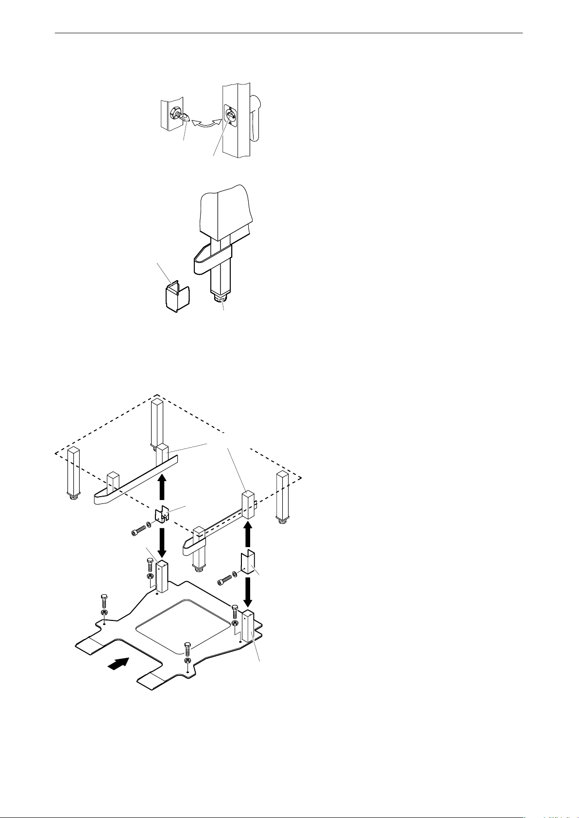
3.3.6 Setup of the upright appliances, e.g. Type 2011
. Align the appliance horizontally to ensure that
. Check after aligning the unit whether the door
Door catch
Door closing
mechanism
Base clamp
D Risk of damage If not set correctly, the door
. Install washers on the wheel attachments of the
D The rack trolley must not brush against the seals
D The seal area of the rack trolley must lie flush
. Secure the appliance against movement.
water is optimally drained from the cooking cham
ber.
closing mechanism properly engages with the
door catch.
closing mechanism may hit the tip of the door
catch and damage it.
rack trolley to align the trolley flush with the coo
king chamber.
of the cooking chamber, and must have a uniform
distance on all sides.
against the lower door seal to ensure closure.
Extend screw base max.
55 mm.
. Secure the front screw bases with the foot
clamps against turning.
3.3.7 Installing the compensation frame for Type 2011/2021 (option)
The compensation frame is required in order to com
pensate for the unevenness of the ground and to
ensure parallel entry into the cooking chamber.
Up to approx. 25 mm unevenness of the ground can
be compensated.
Kit compensating frame Item No. 881895: Suitable
for 881718 plate rack trolley, 880625 GN rack trolley,
879482 BN rack trolley.
Installing compensating frame
. Use the screw feet and align the appliance hori
zontally
1. Remove the Allen screws from the clamps.
2. Push the clamps downwards over the retaining
tube.
1./5.
Square tube
5.
4.
2.
Retaining tube
Clamp, left
1./5.
4.
Clamp,
right
2.
8 / 24
3. Compensation frame not placed beneath the
5.
Square tube
3.
appliance.
4. Push the clamps upwards over the retaining tube.
5. Use an Allen screw to fully tighten the clamps.
6. Horizontally align the compensation frame with
hexagon-headed bolts and lock using hexagon
nuts.
. Check to make sure that the rack trolley can be
moved in parallel to the edge of the cooking
chamber.
Installation instructions
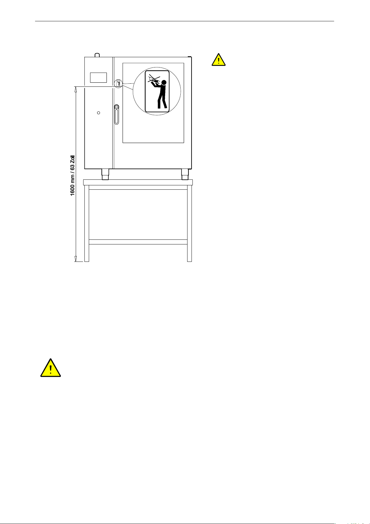
3.3.8 Apply the safety sticker ”Max. shelf level for liquid cooking products”
D WARNING! Scald hazard! Containers
with liquids or products to be boiled, becoming
liquid during the cooking process, may only be
pushed into the slot that can be easily viewed by
the operating personnel.
D Slopping may cause scalding when removing li
quid cooked products!
D For appliance where the top slot for containers is
placed higher than 1.60 m / 63 inches, the sticker
”Max. shelf level for containers with liquid” must
be affixed.
. Affix the sticker at a level of 1.60 m / 63 inches.
Clean the area where the sticker will be affixed
before applying t.
4. Water connection
4.1 Information for water connection
D Obtain information from your local water utility company on the water quality, water pressure and water
hardness.
D Observe the regional regulations and the ”Technical Rules for Drinking Water‐Installations EN 1717”!
D The appliance may only be connected to tap water that corresponds to the potable water regulations.
D There must be no connecting pipes made from galvanized iron or similar material between the water
softening device and the appliance (otherwise risk of rust forming)!
D Observe the installation‐ and user manuals for the water softener.
9 / 24

Installation instructions
4.2 Choice of water softening device / water filter / water treatment
4.2.1 Water treatment systems
D The manufacturers of water softening devices offer systems provided specifically for hot circulating‐air
steamers/combi‐steamers. They may also be combined with particle‐/fine‐ and active carbon filters. We
recommend, for example, the water softener from Brita Co.
D Do not connect the water softener to previously softened water.
D Reverse‐ or osmosis‐systems may generally constitute an economic alternative to full and/or partial
desalination via filtering systems. Osmosis systems remove nearly all hardness‐forming ingredients
and non‐hardened minerals from the water. These systems are also required to remove high chloride‐
and silicate concentrations.
D Particle‐/fine filters with filter grades 5‐15 µm filter, for example, contaminations such as deposits from
water pipes, sand, iron particles or suspended matter. Choose sufficient flow capacity of the fine filter to
prevent any pressure loss and to ensure an adequate flow rate.
D Active carbon filters remove excessive chlorine contents.
4.2.2 Do not use these systems.
D Sodium ion exchangers (as customary with dish washers) are not permitted for these appliances.
Glazing may become dull and irreparable damage may occur in the cooking chamber.
D Systems with phosphate‐ and silicate dosing may not be used. They may cause malfunctions in appli
ance parts and deposits in the cooking chamber.
D Systems based on electromagnetic fields do not provide protection against scale formation with this
type of appliance.
4.2.3 Water hardness conversion table by country
Conversion for the units of water hardness
°dH °e °fH ppm mval/l mmol/l
German degrees 1 °dH = 1 1,253 1,78 17,8 0,357 0,1783
British degrees 1 °e = 0,798 1 1,43 14,3 0,285 0,142
10 / 24
French degrees 1 °fH = 0,560 0,702 1 10 0,2 0,1
ppm CaCO3 (U.S.) 1 ppm = 0,056 0,07 0,1 1 0,02 0,01
mval/l earthy‐base ions 1 mval/l = 2,8 3,51 5 50 1 0,50
mval/l earthy‐base ions 1 mmol/l = 5,6 7,02 10,00 100,0 2,00 1
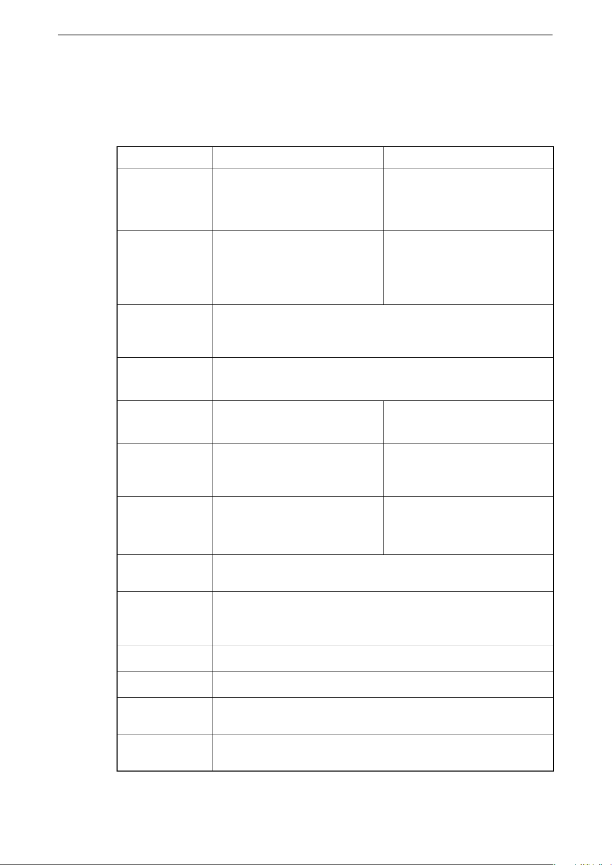
4.2.4 Requirements on the soft‐ and cold‐water connection
D The steam generation in the appliances is carried out as fresh steam, that means, the water is directly
introduced into the cooking chamber.
D The water must conform to the Drinking Water Regulations.
D In order to prevent damage to the appliance, the following requirements must be observed.
Soft water Cold water
Installation instructions
Application For steam generation and automatic
cleaning.
A backflow preventer is installed in
the water supply line.
Water temperature Max. 50°C Cold water (max. 20°C)
Min. water
pressure
Max. water
pressure
Water hardness
°dH
Carbonate
hardness
°dH
A booster pump must be installed if the water pressure is too low. Check the dy
namic water pressure, e.g. with the pull‐out shower opened.
A pressure reducer must be installed if the water pressure is too high.
Total hardness maximal 5°dH
(0.89 mmol/l)
Max. 2°dH
200 kPa = 2 bar (dynamic / flow pressure)
600 kPa = 6 bar (static)
For the steam relief and pull‐out
shower
A backflow preventer is installed in
the water supply line.
Do not connect to hot water due to
excessive water consumption or poor
function of the steam relief (steam
condensation)!
Total hardness maximal 10°dH
(1.783 mmol/l)
Sulphate
SO
4
Chlorine /Chlorine
dioxide content
Chloride Max. 50 mg/l (50 ppm)
Iron Max. 0.1 mg
pH value 6.5 - 7.5
Conductivity
value
Contaminations Install a water filter grade 5‐15 µm to remove, e.g. water pipe deposits, sand, iron
Install a reverse osmosis system
above 10 mg/l; otherwise there is a
risk of damage from glazing corro
sion.
At a chlorine content above 0.1 mg/l (corresponds to 0.1 ppm) an active carbon
filter needs to be installed.
Above 50 mg/l (50 ppm) a reverse osmosis system needs to be installed;
otherwise strongly increased risk of corrosion.
Max. conductivity value 200 µS/cm (micro Siemens)
particles or suspended matter.
11 / 24

Installation instructions
4.3 Connection of soft‐ and cold water
Risk of damage The appliance may not be operated without water connection! A water connection is re
quired even if the appliance is only used for baking!
623T, 611T, 1011T
Cold water
connection
611QT, 1011QT, 2011QT
Cold water
connection
Soft water
connection
Soft water
connection
D The connection requires using a pressure‐resist
ant flexible DVGW‐tested hose with a diameter of
at least 1/2 inch and union of 3/4 inch. Provide a
hose of adequate length to allow the appliance to
be moved during service tasks.
D The appliance are factory‐equipped with a soft‐
and cold water connection. Use the connecting
piece only if you cannot provide separate water
supplies and the specifications for the cold and
soft‐water connections are ensured.
. Rinse through the water pipes in the building sys
tem and supply hoses before connecting.
. Connect the appliance to an easily accessible
water stopcock.
Connection
G3/4 inches
Dirt screen
item‐No. 249688
Water connection
G3/4 inches
Dirt screen
item‐No. 249688
Sealing ring
(included in
connecting piece)
Connecting piece
Item No.: 878801
(cannot be used for
Type T)
D The supply hose may not be kinked or deformed!
. Check that all connections are watertight.
Connection with connecting piece
The connecting piece may be used only if the water
corresponds to the requirements for soft water.
For requirements on the cold‐ and soft water connec
tion, see page 11 Chapter 4.2.4
12 / 24

Installation instructions
5. Connecting water drainage – connection examples
1. Siphon with drain funnel
Device
rear
Siphon with
overflow
At least 2 cm / 1 inch
Open drain funnel
≥ 50 mm
On-site siphon
2. Floor drain with siphon
Recommended for models 2011, 2021 and doubl
rack designs QT
Device
rear
Siphon with
overflow
D It is preferable to use the first or second connec
tion examples!
D The waste water system must be designed ac
cording to DIN 1986‐100 and DIN EN 12056‐1.
D Use steam temperature‐resistant and flame‐retar
dant drain pipe (HT pipe).
D Do not reduce the pipe diameter.
D The diameter of the on‐site drainage pipe must
be at least 50 mm.
D Do not place open drain funnel and water drain in
substructures or under the unit! Condensate may
form from escaping steam! Escaping steam must
be able to move away unhindered and must not
be able to enter electric appliances!
D The manufacturer does not assume any liability
for consequential damages due to incorrect
connection!
D The slope from the appliance to the waste water
connection must be at least 10%!
. To prevent water pouches from forming in waste
water pipes routed freely of extended distances,
the waste water pipe should be fastened at
shorter distances.
. Fill the siphon with water.
3. Wall connection with on-site siphon and vent pipe
We recommend installing a vent pipe when fitting with an
automatic cleaning system and direct connection.
Vent pipe protruding
above top of device
Device
rear
Siphon with overflow
At least
25 cm / 10 inch
On-site siphon
≥ 50 mm
4. Wall mounting (not for Switzerland)
Get authorized Customer Service to install
an odour trap in the appliance: Locate and
attach the hose from the drip plate to the
appliance siphon so that it creates an
odour trap.
Siphon with overflow
Device
rear
≥ 50 mm
13 / 24

Installation instructions
6. Electrical connection
DANGER! Electrical voltage! Risk of electric shock that may result in serious injury or death! Installation,
service and repair tasks may only be carried out by authorised Customer Service.
D If the appliance was transported in a cold environment, it must be stored at least for two hours in a
warm and dry room before making the electrical connection. This prevents condensation of moisture on
the electrical components and their subsequent damage.
D Electrical connection must be carried out by a qualified electrician‐
− according to the applicable VDE 0100 regulations and
− the regulations of the power supply company concerned.
D An electrical main switch must be installed upstream with easy access. The switch must effectively
disconnect the appliance at all poles from the mains. The contact opening must be at least 3 mm.
D Instruct the owner and the operating personnel where the main switch provided in the kitchen for the
appliance is located so that the appliance may be switched off without danger in the event of hazards
to the user.
D Install ground fault circuit interrupter for safety reasons.
623T, 611T, 1011T
Electrical
supply
cable
611QT, 1011QT, 2011QT
Equipotential bonding
Equipotential
bonding
D Comply with the circuit diagram included with the
appliance!
D Table units are supplied with a power cable as
series equipment. If the connecting cables must
be replaced, for example, due to the building
structure, a mains cable of the type H07RNF
according to VDEstandard must be used.
D Observe the data on the type plate when making
the electrical connection.
The appliance must be connected to the equi
potential bonding system (earth connection). Its effi
ciency must be checked in accordance with
VDE0190.
Electrical‐supply cable
14 / 24

6.1 Connection to an energy optimisation unit (option)
Installation instructions
Circuit diagram example
PCB control assembly
6.2 Connection to a load shedding unit
− Load shedding units switch off the consumers in the event of power peaks.
− In the event of switching off by the load shedding unit, the cooking chamber heating is switched off.
− Thereby, heating-up and cooking processes currently being carried out are not taken into considera
tion.
Connection
D A load shedding unit must only be connected by an electrical technician or the authorised customer
service.
D When purchasing the "Connection energy optim
isation" option, the appliance is equipped by the
factory with the necessary interface (ABCD inter
face).
− A = Appliance switched on
− B = Appliance is heating
− C = Requirement (energy optimisation unit)
− D = Neutral conductor (N)
D An energy optimisation unit may be connected
only by an electrical technician or the authorised
customer service.
D Connection, see circuit diagram!
Important:
− For example, if the phases L2 and L3 are switched off by the load shedding unit, the fused power path
(fuse F4) must be reconnected to L1.
− Observe the circuit diagram!
D If connection to L1 is not correct, operation is not possible. An error message is emitted.
7. Initial commissioning
. Remove cartons, foils, accessories, grilles and containers from the cooking chamber.
. Clean outside of the appliance.
. Clean the cooking chamber.
D If a heating process is not possible after transport in cold environments: The safety temperature limiter
cuts off at freezing temperatures. Once the safety temperature limiter has been sufficiently warmed
again from the room temperature, it activates itself automatically.
. Before initial commissioning or after extended operating breaks, fill approx. 5 litres of water into the
cooking compartment drain (overheating protection/(odour trap).
Only for appliances with automatic cleaning system, not for Types 2011:
. Before initial commissioning or after extended operating breaks, fill approx. 5 litres of water into the
cooking chamber drain (overheating protection/odour trap).
D If no water is filled (fault number 4003), this results in destruction of the pumps in the drain system!
Description of cleaning process, see chapter in the operating instructions:
− Connection of the cleaning‐ and rinse‐aid canisters for automatic cleaning (optional)
− Cleaning the appliance and the cooking chamber
15 / 24

Installation instructions
8. Dimensions, connections, technical data
8.1 Dimensions and connections 623T, 611T, 1011T
Width:
623T
611T = 809 mm
1011T = 809 mm
Cooking chamber supply air
38 mm
Cooking chamber
exhaust air
38 mm
Length:
Height:
623T = 764 mm
611T = 764 mm
1011T = 1,004 mm
Electrical connection
Rinse‐aid (blue)
Cleaner (red)
Equipotential bonding
Network connection (LAN)
Cold water 3/4 inches
Soft water 3/4
inches
Drain pipe
dia. 40 mm
623T = 435 mm
611T = 615 mm
1011T = 615 mm
16 / 24
We reserve the right to make technical changes

Installation instructions
8.2 Dimensions and connections 611/621QT, 1011/1021QT
Width:
Length:
795 mm
980 mm
Cooking chamber exhaust air
35 mm
Cooking chamber supply air
Height with bases
611QT = 840 mm
1011QT = 1,120 mm
Cold water 3/4 inches
55
145
75
Soft water 3/4 inches
Equipotential bonding
Rinse‐aid
(blue)
Network
connection (LAN)
63 mm
710
Cleaner
(red)
Electrical
connection
Drain pipe diameter 40 mm
Rear of
appliance
We reserve the right to make technical changes
17 / 24
Installation instructions
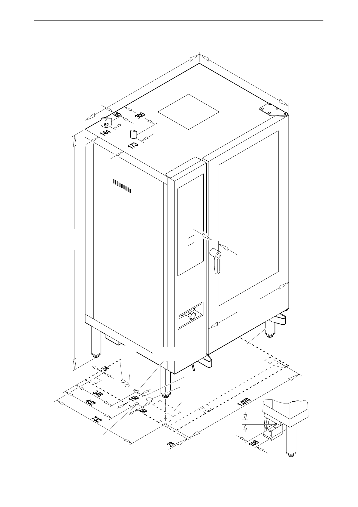
8.3 Dimensions and connections 2011/2021QT
Cooking chamber
exhaust air
Height with
bases
1930 mm
Length:
1115 mm
Width:
880 mm
Cooking
chamber
supply air
63 mm
Cleaner
(red)
Rinse‐aid
(blue)
Soft water 3/4 inches
We reserve the right to make technical changes
Cold water
3/4 inches
Air filter
Width:
785 mm
Base
52x52 mm
Potential equalisation
Electrical
connection
Rear of device
92
Drain pipe diameter 50 mm
18 / 24

8.4 Technical data: 623T, 611T, 1011T
Installation instructions
Technical specifica
tions
623 T 611 T 1011 T
Cooking chamber size 6 x GN 2/3 6 x GN 1/1 10 x GN 1/1
Voltage
Connected load
Fuse
Thermal output, sensi
tive
Thermal output, latent
Steam output
Degree of protection
against water
Appliance noise level
400V 3N 50/60Hz
*)
230V 1N 50/60Hz /
*)
3.8 kW / 6.3 KW 8.6 kW 11.0 kW
3 x 16A
*)
1x16A
0.76 kW
*)
0.46 kW
1.134 kW
*)
0.684 kW
1.67 kg/h
*)
1.01 kg/h
400V 3N 50/60Hz 400V 3N 50/60Hz
3 x 16 A 3 x 16 A
1.03 kW 1.32 kW
1.548 kW 1.98 kW
2.28 kg/h 2.92 kg/h
IPX4 IPX4 IPX4
x70 dB (A) x70 dB (A) x70 dB (A)
Empty weight Approx. 84 kg Approx. 93 kg Approx. 107 kg
8.5 Technical data: 611/621QT, 1011/1021QT
Technical specifica
tions
Cooking chamber size 6 x GN 1/1 10 x GN 1/1 7 x GN 2/1 11 x GN 2/1
Voltage 400V 3N
Connected load 11,0 KW 16.4 kW 18,6 KW 25,5 / 30,7 / 33,5
Fuse 3 x 16A 3 x 25 A 3 x 32 A
Thermal output, sensi
tive
Thermal output, latent 1.98 kW 2.96 kW 3,35 kW 6,03 kW
Steam output 2.92 kg/h 4.35 kg/h 4,93 kg/h 8,87 kg/h
Degree of protection
against water
611 QT 1011 QT 621 QT 1021 QT
400V 3N
50/60Hz
50/60Hz
1.32 kW 1.97 kW 2,23 kW 4,02 kW
IPX5 IPX5 IPX5 IPX5
400V 3N
50/60Hz
*)
230V 3
50/60Hz
*)
3 x 50 A
400V 3 / 3N
50/60Hz
440V 3 50/60Hz
kW
3 x 40 A
3 x 50 A
Appliance noise level
x70 dB (A) x70 dB (A) x70 dB (A) x70 dB (A)
Empty weight Approx. 142 kg Approx. 166 kg Approx. 142 kg Approx. 166 kg
19 / 24

Installation instructions
8.6 Technical data: 2011/2021QT
Technical data 2011 QT 2021 QT
Cooking chamber size 20 x GN 1/1 20 x GN 2/1
Voltage 400V 3N 50/60Hz 400V 3 / 400V 3N
Connected load 34,6 kW / 44,0 kW 51,5 kW / 67,1 kW
Fuse 3 x 63 A 3 x 80 A
Thermal output, sensitive 4,15 kW / 5,28 kW 6,18 kW / 8,05 kW
Thermal output, latent 6.228 kW / 7.92 kW 9,27 kW / 12,08 kW
Steam output 9.169 kg/h / 11.66 kg/h 13,65 kg/h / 17,78 kg/h
50/60Hz
3 x 100 A
Degree of protection against
water
Appliance noise level
Empty weight Approx. 385 kg Approx. 385 kg
IPX4 IPX4
x70 dB (A) x70 dB (A)
8.7 Technical specifications condensation cover (optional)
Technical specifications 623/611/1011 T 611/1011/621/1021 QT
Height of the condensation
cover
Fan speeds 4 4
Fan output 600 m3³/h 1200 m3³/h
Voltage
Connected load 0.06 kW 0.18 kW
Fuse Via device connection Via device connection
Connected inside the Hot air
steamer/ Combi-steamer
150 mm 170 mm
230V 1N 50/60 Hz
230V 1N 50/60 Hz
Connected inside the Hot air
steamer/ Combi-steamer
20 / 24
Appliance noise level
Weight Approx. 22 kg Approx. 40 kg
x70 dB (A) x70 dB (A)

21 / 24

22 / 24

23 / 24

Translation of the original installation instructions
878976 / 7.11 / 12.15
SALVIS AG
Nordstrasse 15
CH‐4665 Oftringen
Tel. +41 (0)62 788 18 18
Fax. +41 (0)62 788 18 98
Internet: www.salvis.ch
E‐Mail: info@salvis.ch
 Loading...