


PRODUCT COMPLIANCE
This product complies with the essential requirements of the following EC Directives:
• Electro-Magnetic Compatibility Directive 2004/108/EC
• Low Voltage Directive 2006/95/EEC
• EC Marking directive 93/68/EEC
SAFETY INFORMATION
These instructions are applicable to the Salus Controls model stated on the front cover of this manual only,
and must not be used with any other make or model.
These instructions are intended to apply in the United Kingdom only, and should be followed along with any
other statutory obligations - if you are in any doubt, please contact the Salus Controls technical helpline.
This accessory must be tted by a Competent person, and installation must comply with the guidance
provided in the current editions of BS7671 (IEE Wiring Regulations) and Part ‘P’ of the Building Regulations.
Failure to comply with the requirements of these publications could lead to prosecution. Always isolate the
AC Mains supply before opening or removing the unit from the wall or wall box.
Please leave these instructions with the end user where they should be kept in a safe place for future
reference.
PLEASE READ THIS INSTRUCTION MANUAL BEFORE USING THE EQUIPMENT.
THIS INSTRUCTION MANUAL MUST BE RETAINED FOR FUTURE REFERENCE.
iT500 User Reference Manual
2

CONTENTS
4 INTRODUCTION
4 Features
5 GETTING STARTED
5 In the Box
5 Optional Equipment
6 INSTALLATION
6 Introduction
10 Installing the iT500RX Receiver
18 Installing the iT500 Thermostat
20 Pairing the iT500 System Units
for the First Time
21 Installing the iTG500 Gateway
22 Installing an iT300
Temperature Sensor
Transmitter (optional)
23 CONTROLS AND DISPLAY
23 iT500 Thermostat Keypad and
Display
25 iT500RX Receiver Controls
26 INSTALLATION
PROGRAMMING
26 Installation Setup Mode
26 Entering Installation Setup
Mode
27 Selecting the System
Conguration
28 Select Heating or Cooling
Mode
29 Select Temperature Units
29 Set the Time Zone
31 Turning Daylight Saving Time
On or O
33 PAIRING THE iT500 AND
iT300 WITH THE iT500RX
33 Pairing the iT500 Thermostat
with the iT500RX Receiver
35 Pairing an iT300 with the
iT500RX Receiver (optional)
37 Registering your iT500 Online
40 Download the Smartphone
App
43 USER PROGRAMMING
43 Program Times and Setpoint
Temperatures
45 Default Program Schedules
46 Control using the PC or
Smartphone App
51 Local Control using the
iT500TR Thermostat
59 Override Central Heating Zone
Settings
61 Override Hot Water Settings
64 Other Overrides
65 Frost Protection
65 Lock and Unlock the Keypad
66 OTHER INFORMATION
66 Low Battery Indication
66 Battery Installation or
Replacement
67 Resetting the iT500
Thermostat
68 Firmware Updates
69 TECHNICAL SPECIFICATIONS
69 Operating Environment
69 iT500 Central Thermostat
70 iT500RX Thermostat Receiver
70 iTG500 Gateway
71 iT300 Temperature Sensor
Transmitter
iT500 User Reference Manual
3

INTRODUCTION
Thank you for choosing the Salus iT500 Series of Internet enabled programmable heating/cooling controls.
We hope that your purchase will give you many years of active and trouble-free service.
This equipment can replace an existing domestic central heating and hot water programmable controller and
thermostat or can control a completely new installation.
It is estimated that using a programmable thermostat can save up to 20% of the energy used by a traditional
installation.
The equipment can be used without the Gateway unit. In this case the battery powered central Thermostat
unit will communicate only with the Thermostat Receiver and cannot be accessed remotely.
Features
• Access and control your heating and hot water system via the internet using a smartphone or computer
• Programmable using your smartphone or computer
• Secure and energy ecient
• Three system and display congurations
iT500 User Reference Manual
4

GETTING STARTED
In the Box
Optional Equipment
The iT500 Thermostat - replaces your xed hardwired thermostat and
also the timer or programmable part of your heating controller. This unit
communicates with the iT500RX Receiver. It can be located anywhere in your
home as it is portable and battery powered.
Includes: 2 x AA Alkaline Batteries.
The iT500RX Receiver - replaces the switching part of your timer or heating
controller that is hardwired to your boiler, pump and 3-way valve. It allows for
manual override in the event of failure of your iT500 Thermostat unit.
The iTG500 Gateway - connects to your router and enables you to control
your central heating and hot water controls from outside of your home, via a
smartphone or computer.
Includes: 12V Power Supply and Ethernet Cable
The iT300TX Temperature Sensor Transmitter - replaces the second
hardwired thermostat in a two zone heating system. It can be located in
any part of the zone as it is portable and battery powered, can also be wall
mounted.
Purchased separately.
iT500 User Reference Manual
5

INSTALLATION
Introduction
The iT500 Thermostat and the iT500RX Receiver are designed to replace the programmer and wired
thermostat in a traditional domestic heating arrangement.
The equipment can be congured to control the following arrangements:
• Heating only, 1 zone
• Heating only, 2 zones
• Heating plus hot water
The system can be remotely controlled, via the internet, by connecting the system to your wireless router.
iT500 User Reference Manual
6
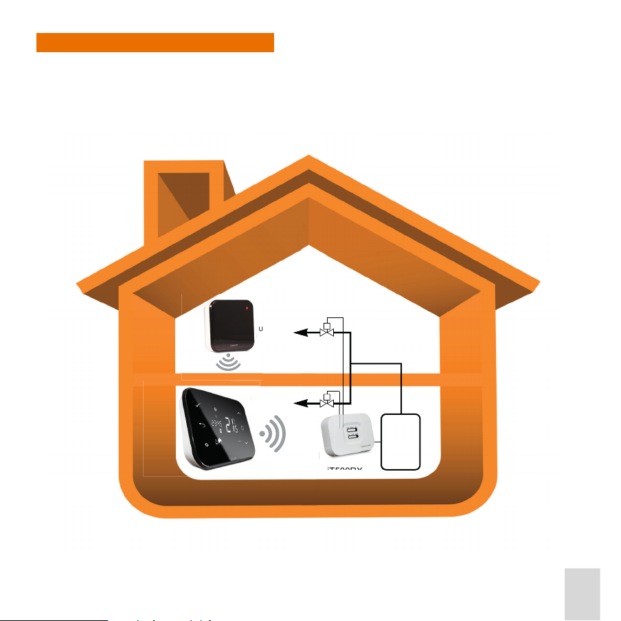
Two Heating Zone Arrangement
R
DO
A
30
0
U
1
In this arrangement, the two outputs on the iT500 Thermostat Receiver are used to control two zone heating
valves.
The temperature in Zone 2 is controlled by the addition of an iT300 Temperature Sensor Transmitter, placed
in the zone.
Zone 2
UPSTAIRS
RADIATORS
iT300TX
T
TX
DOWNSTAIRS
RADIATORS
R
Boiler
Zone 1
iT500TR
iT500T
iT500RX
iT500 User Reference Manual
7
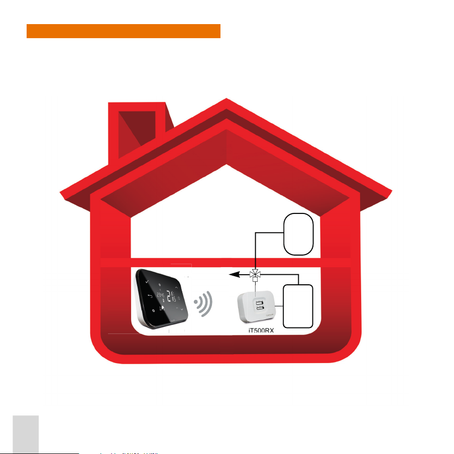
Heating plus Hot Water Arrangement
Hot
Water
Tank
Boiler
iT500
iT500RX
ALL RADIATORS
iT5
00
L
This is the arrangement for installing an iT500 based control system with a single heating zone and hot water.
The iT500RX Receiver is hardwired to the heating and water system components.
The iT500 Thermostat is connected wirelessly to the iT500RX Receiver.
iT500 User Reference Manual
8

Connection to the Internet
i
To control the system via your smartphone or a remote computer, the system can optionally be connected to
the Internet. The iT500 Thermostat is connected to your existing broadband router, using the iTG500
Gateway.
iTG500
TG500
Router
Internet
iT500
iT500 User Reference Manual
9
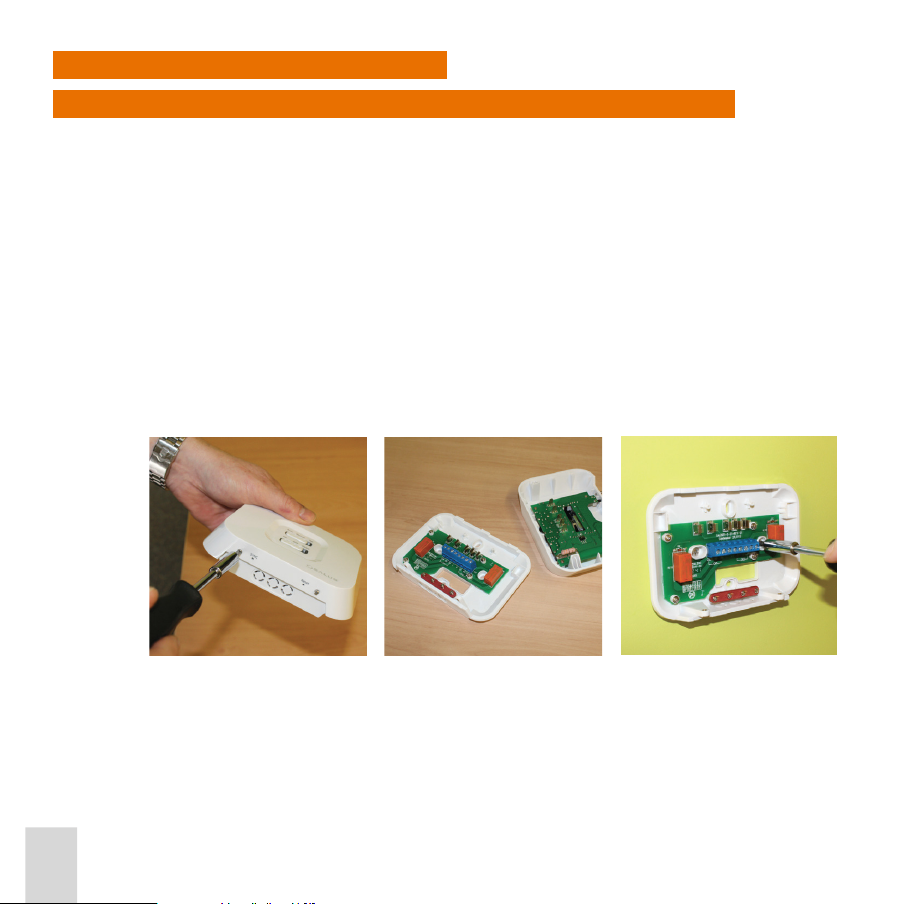
Installing the iT500RX Receiver
Replacing an Existing Programmable Controller with the iT500RX Receiver
1. Turn o the electrical power to your appliance.
Caution: Ensure that the electrical supply to the appliance has been isolated. Failure to completely
Remove the cover from the existing programmable controller.
2. Note down the wiring sequence and the cable colours connected to the terminals within the electrical
box.
3. Disconnect the wires from the existing programmable controller terminals and remove.
Note: Providing the existing programmable controller was mounted using a standard electrical box, the
4. Loosen the screws at the bottom of the receiver unit, unclip the front of the unit and t the back of the
receiver unit to the wall using the ttings supplied.
isolate the appliance could cause personal injury by electric shock and possible damage
to equipment.
iT500RX Receiver will nally mount back onto this.
iT500 User Reference Manual
10
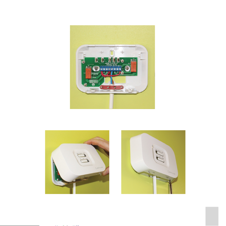
5. Connect the wires in the electrical box to the terminals of the iT500RX Receiver in the correct sequence.
See the wiring diagram later on in this section.
6. Once the wiring has been completed, position the iT500RX Receiver over the electrical box xing holes.
Carefully position any wiring back into the electrical box and secure the iT500RX Receiver using the
existing screws.
iT500 User Reference Manual
11
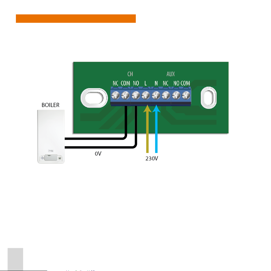
Installing in a New Heating Installation
Install a new electrical box and connect the wires as detailed in the wiring diagrams below.
Volt Free - Combination Boiler
iT500 User Reference Manual
12
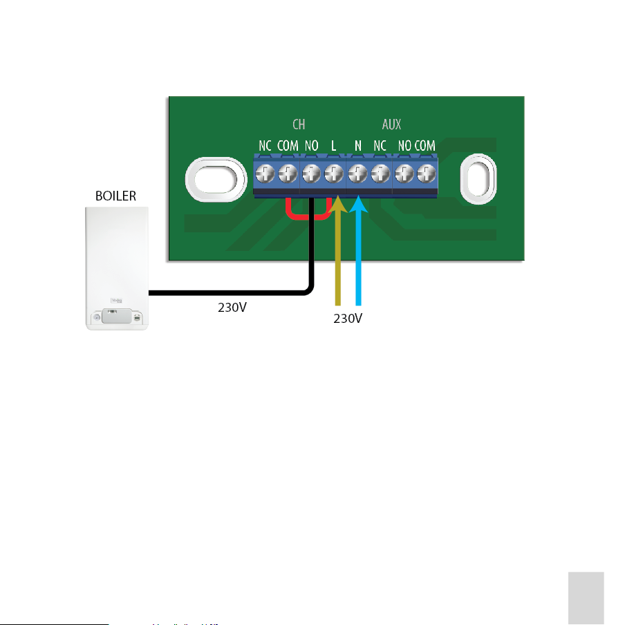
230V Switching - Combination Boiler
iT500 User Reference Manual
13
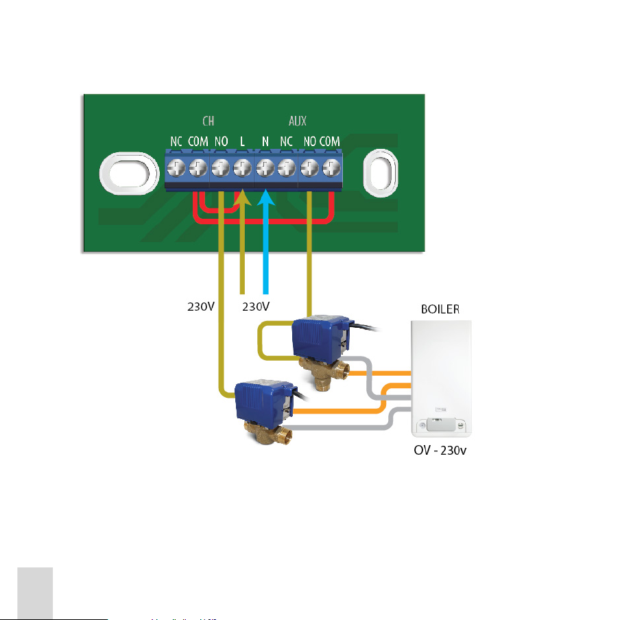
2 x CH Zones - Volt Free Combination Boiler
iT500 User Reference Manual
14
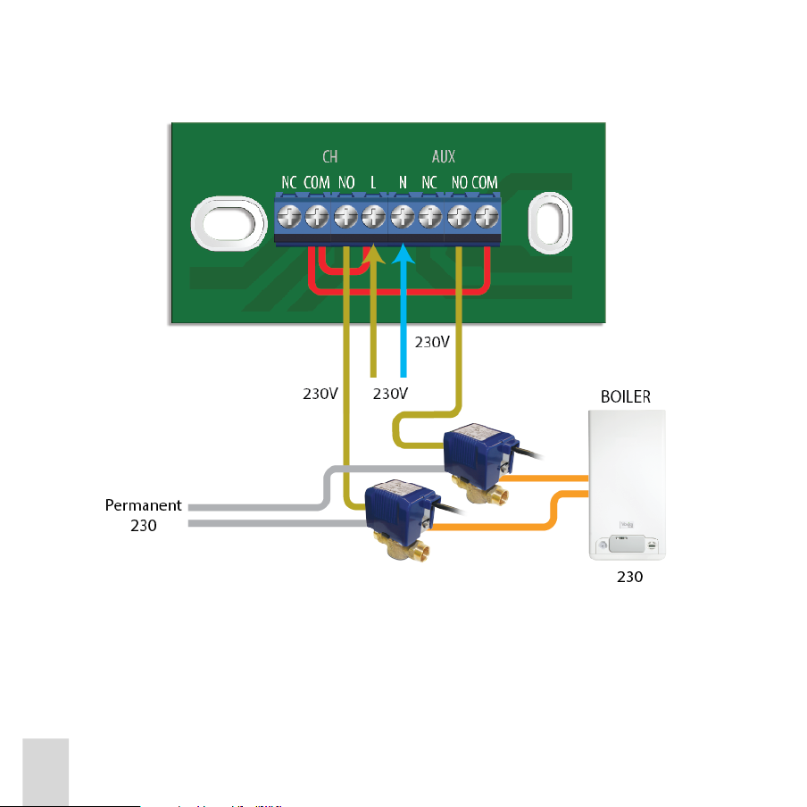
230 V Switching - S Plan
230V
230V
230V
230 V Switching - S Plan
BOILER
Permanent
230V
2C
iT500 User Reference Manual
15
2 x CH Zones - 230 V Switching Combination Boiler
iT500 User Reference Manual
16
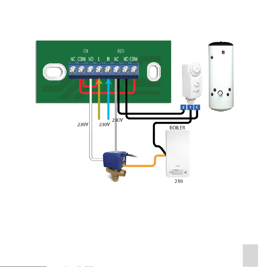
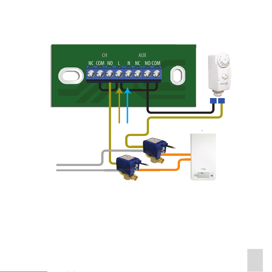
230 V Switching - Y Plan
iT500 User Reference Manual
17

Installing the iT500TR Thermostat
The iT500 Thermostat is portable and can be located anywhere, providing it is within range of the iT500RX
Receiver.
If necessary, install the batteries in the iT500 Thermostat (see Battery Replacement).
Fit the wall mounting bracket and clip the Thermostat to the wall, as follows:
1. Attach the wall mounting bracket to a suitable wall using the ttings supplied and the built in level.
Note: For best results mount the iT500 Thermostat 1.5m from ground level.
2. After rst ensuring that the bracket is secure, clip the iT500 Thermostat into place by aligning the recess
on the back of the unit to the bracket and clipping into place.
3. Once clipped into place, ensure the unit is securely seated on the bracket.
iT500 User Reference Manual
18
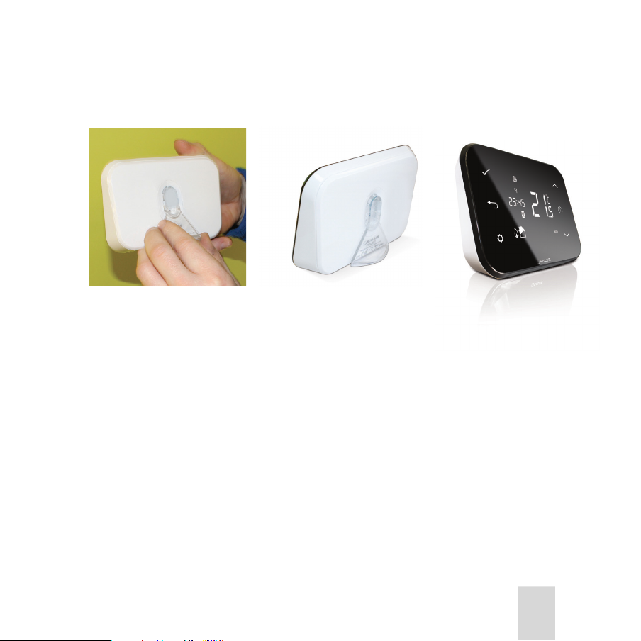
Alternatively, position the iT500 Thermostat on a at surface, using the stand provided.
Simply clip the clear stand supplied separately into the back of the unit.
iT500 User Reference Manual
19
Pairing the iT500 System Units for the First Time
Once the iT500 Thermostat and the iT500RX Receiver are physically installed, the two units need to be ‘paired’.
Pairing allows the two devices to recognise each other and to communicate wirelessly.
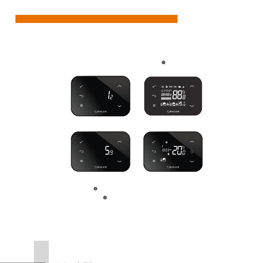
When powering on the iT500TR Thermostat for the rst time, the Thermostat will go through the sequence
of screens shown below and automatically try and pair by searching for the strongest signal from an iTG500
Gateway.
The units attempt to pair for 10 minutes and during this time, the
approximately 20 seconds.
icon will ash. Pairing should take
OTA (Over the Air) Software
Revision Number
iT500 Software Revision
Number
If the pairing is successful, the
If the pairing fails or times out, the
iT500 User Reference Manual
20
icon is turned on all the time.
All Display Icons
Home Screen
icon will disappear and the system will retry later.
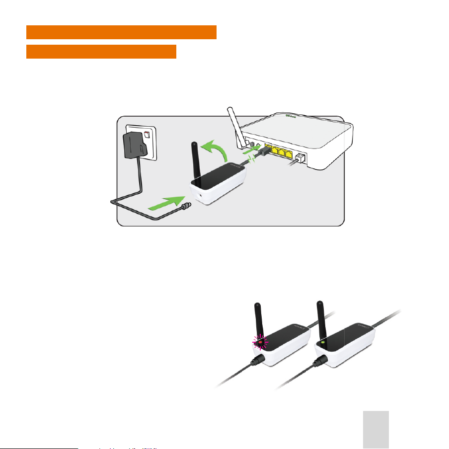
Installing the iTG500 Gateway
Connecting to your Router
Using an RJ45 cable, connect the Gateway to your router (connected to the internet), connect the supplied
power cable to the Gateway and plug it into the 230V power supply. When all the connections are completed,
turn on the power supply. This is the rst step in enabling you to control your central heating from outside of
your home using your mobile phone or a remote computer.
The light on the router will ash red when it is rst connected and setting up. When connected to the SALUS
Controls Server it will display a constant green light.
Note: Check that your router is allowing the gateway access to both incoming and outgoing connections.
See your router’s operation manual for details on security and TCP/UDP port settings.
1. The gateway requires a xed IP address.
2. You require port 80 and 2165 UDP open.
3. Estimated use per month is 20mb.
iT500 User Reference Manual
21
Installing an iT300TX Temperature Sensor Transmitter (optional)
The iT300TX Temperature Sensor Transmitter is purchased separately. It is only used if your system supports
two central heating zones. The unit is portable and should be located in the area of your home heated by the
Zone 2 radiators.
1. Remove the battery cover on the back of the iT300TX.
2. Insert the 2x AAA batteries supplied into the iT300TX.
3. Replace the battery cover.
4. Attach the wall mounting bracket to a suitable wall using the ttings supplied.
5. Align the grooves on the back of the iT300TX and slide onto the bracket.
6. Once in place, ensure the unit is securely seated on the bracket.
iT500 User Reference Manual
22

CONTROLS AND DISPLAY
iT500TR Thermostat Keypad and Display
Keypad
The Thermostat keypad provides six keys for conguring and setting your heating and hot water system.
These are virtual keys, areas of the capacitive screen. An internal reset key is also provided for resetting the
unit.
Short press to conrm selection
Display ON
Short press to return to previous
screen or previous item. In Program
Mode, long press to return to home
screen without saving. In Manual
Override Mode, long press to return to
Auto Mode. In Auto Mode, long press to
enter OUT mode.
Scroll up/down a menu.
Increase/decrease a setting
value. Single press advances
value by a single digit. Holding
rolls value sequentially..
Long press to enter Setting Mode.
In Setting Mode, short press to make
changes or save changes.
Reset Key (internal) Restores factory presets. In Setting
Mode, press and hold to cycle through current settings.
iT500 User Reference Manual
23

Display
Indicates
unit is in Setting
Mode.
Days of the week, current day only
displayed
Clock, with 12/24 hour clock indication.
Program number, active program displayed
Zone 1 Heating indicator
Heating on indicator
Cooling on indicator
Indicates
internet
connection is
active.
Indicates
wireless
communication
is active,
transmitting or
receiving.
Zone 2 Heating indicator
Heating on indicator
Cooling on indicator
Low battery
warning symbol.
If ashing, very
low battery.
ON Continuously on
1 On once a day from program 1 ON to program 3 OFF
AUTO Running in auto
OFF Continuously o
Indicates
that the Holiday
override is
active.
active, heating is on.
Temperature indicator, current
ambient temperature displayed
Operation indicator
Hot Water indicator
Hot Water on indicator - qualied below:
Indicates that
the keypad is
locked. Press
and together
to unlock.
Indicates Frost Protection is
Notes:
• Indicators change during programming, becoming displays of selectable options or setpoint indicators.
• The
and icons are not used on this model.
iT500 User Reference Manual
24

iT500RX Thermostat Receiver Controls
The iT500RX provides manual control of the system in the event that the wireless connection fails.
Auto - Manual - O - switches
Auto -system controlled by
programs in iT500TR Control
Thermostat
Manual - system continuously on
O - system continuously o
Ch - Aux - Ch/Aux - switches
Should be set to match controlled
system i.e.:
Ch -heating only, 1 zone
Aux - heating only, 2 zones
Ch/Aux - heating (1 zone) plus
hot water
Auto Manual Off
Ch Aux Ch/Aux
iT500 User Reference Manual
25

INSTALLATION PROGRAMMING
Installation Setup Mode
The following installation setup options can be set:
1. System Conguration – One Central Heating Zone, Two Central Heating Zones or One Central Heating
Zone plus Hot Water.
2. Heating Mode or Cooling mode for the selected System Conguration.
3. Whether temperature is to be displayed in Centigrade or Fahrenheit.
4. The Time Zone setting, for example GMT, GMT+1 etc.
5. Whether or not Daylight Saving is on.
The default settings that the iT500 comes with are:
• One Central Heating Zone, Heating Mode, temperature in Centigrade, GMT, and DST turned on.)
Entering Installation Setup Mode
Unless the display is already on, press the Display ON button . The display then switches on with the Home
screen displayed.
Press and hold down both the Settings button
iT500 will then go into Installation Setup mode.
The rst setting to be specied is the system conguration. While in Installation Setup mode, if this or any
other setting is already set the way you want, just press the Conrm button
to the next setup option.
For example, if the system conguration is already set to the required option, press the Conrm button
step through to the Heating or Cooling mode selection option.
Press and hold
iT500 User Reference Manual
26
and the Increase button together for two seconds. The
to accept that setting and go
to
to exit Installation Setup Mode and return to Normal mode at any time.

Selecting the System Conguration
The rst step is to select the system conguration, as follows:
1. When the iT500TX enters Installation Setup mode, the display changes to show the Zone 1
and Hot Water
2. Press the
3. Press the
icons ashing:
button. The display then changes to show the ashing Zone 1 icon only:
This is the indicator for the single central heating zone system
conguration. If this is the system conguration you want, press the
button again.
and buttons to cycle through the three dierent system congurations.
This is the indicator for the two central heating zones system
conguration. Press the button to select this system
conguration.
This is the indicator for the single central heating zone plus hot
water system conguration. Press the Conrm button to select
this system conguration.
, Zone 2
Once the required system conguration has been selected, other installation options may be selected, as
described next.
iT500 User Reference Manual
27

Select Heating or Cooling Mode
You can now select whether heating or cooling is required for the system conguration you selected
previously.
1. Once a system conguration has been specied, the system conguration icon is displayed again, but this
time with the Heating mode indicator
or or
next to each icon:
This indicates that heating mode is selected. Press
2. If Cooling mode is required, press the
displayed with the Cooling mode icon
Press
iT500 User Reference Manual
28
if this is the mode that you require.
button instead. The system conguration icons are then
next to them:
or or
to select Cooling mode.

Select Temperature Units
After Heating or Cooling mode has been selected, you can select the units that temperatures will be
displayed in: (°C) or (°F). The screen displays the Centigrade unit by default:
Press
If you prefer Fahrenheit press
if Centigrade is your preferred choice.
or . The screen then displays the Fahrenheit unit:
Press .
Set the Time Zone
After the temperature units have been selected, you can select the appropriate time zone for your location
(see European Time Zones, below).
The display shows the default time zone (0):
or to select the required time zone.
Press
• Press
• Press
Press
to select 0, 1, 2, 3, in sequence.
to select 0, -1
.
iT500 User Reference Manual
29

European Time Zones
iT500 User Reference Manual
30

GMT GMT +1 Hour GMT +2 Hours GMT +3 Hours
UK AUSTRIA BELARUS* RUSSIA *
IRELAND BELGIUM BULGARIA
PORTUGAL BOSNIA CYPRUS
ICELAND* CROATIA ESTONIA
CZECH REPUBLIC FINLAND
DENMARK GREECE
FRANCE LATVIA
GERMANY LITHUANIA
HOLLAND MOLDOVA
ITALY ROMANIA
LUXEMBOURG RUSSIA
MA LTA TURKEY
NORWAY UKRAINE
POLAND
SERBIA
SLOVENIA
SPAIN
SWEDEN
SWITZERLAND
Note: The countries marked with * do not observe Daylight Saving Time.
iT500 User Reference Manual
31

Turning Daylight Saving Time On or O
After the time zone has been selected, you may choose to turn Daylight Saving Time (DST) on or o.
The screen displays the default DST setting (ON):To set DST on, press
To turn DST o, press the
Press
iT500 User Reference Manual
32
to set DST o.
.
or buttons once. The screen then displays as follows:

PAIRING THE iT500TX WITH THE iT500RX and iT300
Pairing the iT500 Thermostat with the iT500RX Receiver
For the iT500 Thermostat and the iT500RX Receiver
to communicate wirelessly, they must be “paired” as
follows:
When the iT500TR Thermostat in Normal mode press
and together for two seconds.
The
then ashes and then press .
Display shows the number “10”. This is the time in
minutes that the iT500TR transmits its wireless signal.
Press to return to home screen.
iT500 User Reference Manual
33

Pairing the iT500 Thermostat with the iT500RX Receiver
Using a paper clip, insert into the hole marked SYNC at the
bottom of the iT500RX Receiver.
The bottom switch will show a constant red light when the
iT500RX. Receiver is ready to pair.
When the iT500RX Receiver and the iT500 Thermostat are
powered and paired then the light will be green.
iT500 User Reference Manual
34

Flashing blue light indicates a heat call/Hot water call.
FAILSAFE MODE: In the event of RF signal loss, your system
will be switched on for 4 minutes, then o for 11 minutes. If
you want to disable FAILSAFE MODE when RF link has been
lost then move the slide switch on the iT500RX to either the
manual or o position.
NOTE: Please go through pairing sequence again if the
switch goes orange.
iT500 User Reference Manual
35

Pairing an iT300 with the iT500RX Receiver (optional)
The iT300 is purchased separately. It is only be used if your system supports two central heating zones.
To pair the iT300 to the receiver, insert a paperclip or similar object into
the hole on the left hand side of the iT300 for 2 seconds.
A red light will ash in the top right hand corner of the iT300TX.
iT500 User Reference Manual
36
With the iT500 Thermostat in Normal mode press
two seconds. The following will be displayed.
Press to start sync. count down.
The units will be paired once the count down has nished.
and together for

Registering your iT500TR Online
Before your IT500TR Thermostat can be controlled remotely, it must be registered on the SALUS website.
1. To register your iT500 online, go to the SALUS controls website. www.salus-controls.com .
2. Select your country:
3. Click on the register your iT500 icon on the left hand side of the country’s website:
iT500 User Reference Manual
37

4. Click on REGISTER, then complete the form that is displayed and click REGISTER again.
5. The screen below will then be displayed and a conrmation e-mail will be sent to the e-mail address you
entered in the form.
iT500 User Reference Manual
38

6. Now use your username and password to log in, then enter the STA number ( found in the battery
compartment on the iT500) and press REGISTER.
7. Your iT500TR will appear as below and is now ready to be controlled or viewed via your PC or
Smartphone. Just click on the iT500 icon on your PC.
iT500 User Reference Manual
39

Download the Smartphone App
Once you have registered your iT500 online you can download the smartphone App from the iPhone App
Store or the Android App Store, depending on which kind of Smartphone you are using. Find the iT500 App
on the App Store and click download. The App will automatically download to your Smartphone. Once it is
downloaded, you can start controlling your iT500TR Thermostat using the App.
1. Go to the SALUS controls website: www.salus-controls.com.
2. Click on the relevant App Store Icon:
3. Find the SALUS iT500 App in the selected store and download it.
iT500 User Reference Manual
40

Adding or Renaming the iT500 in your Device List
Enter your user ID and password.
Press LOGIN.
When you rst open the iT500 App
your iT500TR will appear in the device
list and you can start controlling it
with your Smartphone.
iT500 User Reference Manual
41

If you add more than one iT500 to your
device list, you may wish to rename the
iT500 to “DOWNSTAIRS” for example. Click
on RENAME and enter a new name.
If you forget your password, follow
the onscreen instructions.
iT500 User Reference Manual
42

USER PROGRAMMING
Using the PC or Smartphone App remotely, or the iT500 Thermostat unit locally, you can programme in your
central heating and hot water settings as required.
Before doing this, you should identify your system conguration, as described next.
Identify your System Conguration
There are three possible system congurations:
• One Central Heating Zone
• Two Central Heating Zones
• One Central Heating Zone plus Hot Water
iT500 User Reference Manual
43

Note: The system conguration is specied by your installer and should only subsequently be changed
by the installer.
Once you have identied your system type, you can use your PC or smartphone to fully control your iT500.
This can be done using your PC or Smartphone app, or locally on the iT500.
Program Times and Setpoint Temperatures
You can specify from which times heating may come on and what temperatures will trigger this (or use the
deafult settings described next).
For the One Central Heating Zone and Two Central Heating Zone system congurations you have the
following options:
• Number of programs per day:
For each day or day group up to 6 programs can be dened. A program consists of a start time and a
temperature setpoint. Start times must be set sequentially, i.e. start time for program 2 must be later
than start time for program 1. Failure to set the start times sequentially will result in conicts and the
conicting start times will have to be re-set.
• Temperature setpoint can be set for each program time period.
• Days the programs apply to:
Days are numbered 1 to 7 where 1 is Monday and 7 is Sunday.
Days can be programmed individually or in groups. Groups are as follows; 1-2-3-4-5 (weekdays) plus 6-7
(weekends), or 1-2-3-4-5-6-7 (whole week).
In other words you can set up dierent programs for the weekend compared to weekdays, or have the
same programs for the whole week, or have the dierent programs for every day of the week.
For One Central Heating Zone plus Hot Water you have the same program options as above for the central
heating zone. For the hot water you have the following options:
• Number of programs per day:
For each day or group of days (weeks, weekdays and weekends) up to 3 program ON/OFF times can be
set. These must be set sequentially, i.e. the OFF time for program 1 must be later than the ON time for
program 1, the OFF time for program 3 must be later than the ON time for program 3.
Failure to set programs sequentially will result in conicts which will have to be re-set.
• Days the programs apply to:
Same as for above.
iT500 User Reference Manual
44

Default Program Schedules
Your iT500 Thermostat comes pre-set with these default program schedules. These can be easily changed via
the PC or Smartphone App, or locally using the iT500 Thermostat unit if required.
Central Heating
PROGRAM WEEKDAY (1 to 5) WEEKDAY (6 to 7)
1 Time 6:00am
2 Time 8:00am
3 Time 11:00am
4 Time 1:00pm
5 Time 4:00pm
6 Time 9:00pm
Setpoint Temp 21ºC. ON
Setpoint Temp 14ºC. OFF
Setpoint Temp 21ºC. ON
Setpoint Temp 14ºC. OFF
Setpoint Temp 21ºC. ON
Setpoint Temp 14ºC. OFF
Hot Water
PROGRAM OP WEEKDAY (1 to 5) WEEKDAY (6 to 7)
1 ON
OFF
2 ON
OFF
3 ON
OFF
6:00am
8:00am
10:00am
12:00pm
6:00pm
10:00pm
Time 6:00am
Setpoint Temp 21ºC
Time 8:00am
Setpoint Temp 14ºC
Time 11:00am
Setpoint Temp 21ºC
Time 1:00pm
Setpoint Temp 14ºC
Time 4:00pm
Setpoint Temp 21ºC
Time 9:00pm
Setpoint Temp 14ºC
6:00am
8:00am
10:00am
12:00pm
6:00pm
10:00pm
iT500 User Reference Manual
45

Control using the PC or Smartphone App
Common Settings and Indicators
The interface for all three system congurations for both the PC and the Smartphone app includes the
following common settings and indicators:
Energy save will use the lowest set temperature on your
daily schedule.
Will be displayed when the current program has been
manually overridden
Press AUTO to cancel the temporary override of program
temperature.
iT500 User Reference Manual
46

Follows
weekly
schedule
Energy
save
mode
Home Holiday Settings Back
Heating continu-
ously
o
Override
program
temperature*
Change/view
weekly heating
schedule
Current
program
One Central Heating Zone
The interface for the PC and the Smartphone app for the One Central Heating Zone System Conguration:
iT500 User Reference Manual
47

Two Central Heating Zones
The interface for the PC and the Smartphone app for the Two Central Heating Zones System Conguration:
iT500 User Reference Manual
48

One Central Heating Zone plus Hot Water
The interface for the PC and the Smartphone app for the One Central Heating Zone plus Hot Water System
Conguration:
iT500 User Reference Manual
49

iT500 User Reference Manual
50

Local Control using the iT500TR Thermostat
Local control and user programming using the iT500 Thermostat is carried out with the iT500 in Settings
mode. Settings mode is used to:
• Set the time (hour/minutes/day/month/year/DST setting)
Note: When the iT500 is connected to the internet the time and date are set automatically.
• Set program times and setpoints
• Review programs
Entering Settings Mode
In Normal (Home) mode press for 2 seconds (long press). The unit then enters Settings mode. The icon
is displayed when the unit is in Settings mode. When you rst enter Settings mode, apart from the icon,
only the days of the week and the Zone and Hot Water icons (depending on your System Conguration) are
displayed (ashing). For example:
Setting the Time and Date
Set the time and date as follows:
1. With the unit in Settings mode, press
to enter Clock Setting mode.
Press the Conrm button .
iT500 User Reference Manual
51

2. Select 12 hour or 24 hour clock.
The display will show the current setting, 12 hr or 24 hr. If this is the
setting you want, press .
Press or to change between 12hr and 24hr. Press to
conrm the selection.
3. The current time is displayed, with the hours ashing:
Press to conrm the hour, or to change it press or until
the required hour is displayed and then press .
4. After the hour has been set and conrmed, the current time is displayed with the minutes ashing. Press
or until the required minute is displayed and then press ..
iT500 User Reference Manual
52

5. The current date is displayed in day / month format. The day of the month will be ashing:
Press to conrm the day, or to change it press or until the
required day is displayed and then press .
6. After the day has been set and conrmed, the current date is displayed, with the month ashing. Press
to conrm the month, or to change it press or until the required month is displayed and press .
7. After the month has been set and conrmed, the current year is displayed, with the year ashing. Press
to conrm the year, or to change it press until the required year is displayed and then press
.
After
is pressed the unit returns to Normal mode.
iT500 User Reference Manual
53

Setting the Program Schedule for Central Heating Zones
In Settings modes you can specify time periods and a desired temperature for each of the time periods.
1. From Normal mode, enter Settings mode by pressing
Press ..
2. If your system conguration is Two Central Heating Zones or One Central Heating Zone plus Hot Water,
you now have to select which of these you want to set the schedule for. On the screen, the Zone 1 icon
will ash.
If this the zone you want to program for press ..
If you want to program for the other zone (or for hot water),
. The Zone 2 (or hot water) icon will then ash. Press
press
..
If your system conguration is One Central Heating Zone then that zone is selected automatically.
Note: To step backwards through the programming procedure press
procedure and turn to Normal mode press and hold for 2 seconds.
for 2 seconds.
. To exit the programming
iT500 User Reference Manual
54

3. Next, you must select either the day or group of days that the programs are to be applied to. The days of
the week on the display will ash, initial the weekdays.
If you want to set up programs for the weekdays group of days,
press . Otherwise press .
The weekend day numbers will then be displayed ashing
instead. To program for these press
The day numbers for the entire week will then be displayed
ashing, To program for these press
., otherwise press .
., otherwise press .
The individual days of the week will then be displayed ashing, one after the other. Press
programs for a day, or press to go to the next day.
After you have selected which days or day to set up a program schedule for, you ready to set up program 1.
The program you are currently setting up is indicated by the number shown in the displayed under the time for example see the number 1 with the white background in the screen example above.
4. The rst stage in setting up a program is to specify the start time. The hour setting on the display will
ash. Press
and move on to minute setting.
or to increase or decrease the hour setting or press to accept the current setting
iT500 User Reference Manual
to set up
55

5. The minute setting then ashes. Adjust and conrm it in the same way as the hour setting. Each press of
or increases or decreases the minute setting by 10 minutes.
6. Next, specify the setpoint temperature. The currently programmed temperture for the program will ash.
Use the
conrm.
7. Programming for program 1 is now complete. The unit then switches to program 2, as indicated by the
displayed program number:
8. Repeat steps 4 to 6 for program 2, and then for programs 3 to 6 in turn.
9. If the weekdays group of days was selected, the unit then switches to the weekend group of days so that
you can specify the separate programs for the weekend.
iT500 User Reference Manual
56
and buttons to increase or decrease the temperature by 0.5 °C or 0.5 °F, and press to

Day numbers 6 and 7 will be shown on the display:
If the weekend group of days was selected, the unit then
switches to the weekdays group of days so that you can specify
the separate programs for the weekdays. Day numbers 1 to 5
will be shown on the display.
One the programs for both the weekdays and weekend have
been set up, the unit automatically returns to Normal mode.
If the entire week group of days was selected, the unit automatically returns to Normal mode once the 6
programs have been set up.
If individual days were selected, the unit automatically returns to Normal mode once the 6 programs for
each individual day have been set up.
Setting the Program Schedule for Hot Water
1. From Normal mode, enter Settings mode by pressing for 2 seconds. Then Press
2. On the screen, the Zone 1 icon
enter hot water programming.
3. Select the days or group of days to program for as described in step 3 above.
will ash. Press . The Hot Water icon will then ash. Press to
iT500 User Reference Manual
57

4. You can now enter the On and O times for program 1. First, enter the On time. ON is shown on the
display and the hour setting ashes. Press
accept the current setting and move on to minute setting.
5. The minute setting then ashes. Adjust and conrm it in the same way as the hour setting. Each press of
or increases or decreases the minute setting by 10 minutes.
6. OFF is then shown on the screen and the hour setting ashes again. Specify the O time hours and
minutes for program 1 in the same way as you did the On time.
or to increase or decrease hour setting or press to
7. Programming for program 1 is now complete. The unit then switches to program 2, as indicated by the
displayed program number. Repeat steps 4 to 6 for program 2, and then for program 3 in turn.
iT500 User Reference Manual
58

8. Depending on which days you selected to program for you may then be prompted to program for
another group of days or individual days as described in step 9 above. Hot water programming is then
complete and the unit automatically returns to Normal mode.
Override Central Heating Zone Settings
Override Setpoint Temperatures for a Central Heating Zone
To temporarily override the setpoint temperatures, in other words to set the central heating to come on and
maintain a temperature you choose at the time, instead of according to its current program, carry out the
following steps:
1. If your system conguration is One Central Heating Zone, or if it is Two Central Heating Zones and you
want to override the current setpoint temperature for Zone 1, or if it is One Central Heating Zone plus Hot
Water, simply press
If your system conguration is Two Central Heating Zones and you want to override the current setpoint
temperature for Zone 2, press
2. The setpoint temperature of the current program is then displayed:
or .
to switch to Zone 2, and then press or .
3. Press
Press
or . to increase or decrease the temporary setpoint temperature.
to cancel setting the override and return to the Home display.
iT500 User Reference Manual
59

4. To conrm the override, press . The Home screen is then displayed again.
Note that the “AUTO” status indicator is no longer displayed in the
bottom-right hand corner of the screen, and the icon is displayed
in the top-left corner, indicating that an override has been set.
Temporary setpoints are cancelled at the end of the program in which they have been set. To turn o an
override before then, press and hold
Turn O Central Heating for a Central Heating Zone
Central heating for a zone can be turned o, as follows:
1. If your system conguration is One Central Heating Zone, or if it is Two Central Heating Zones and you
want to turn o heating for Zone 1, or if it is One Central Heating Zone plus Hot Water, simply press
and
together.
If your system conguration is Two Central Heating Zones and you want to turn o heating for Zone 2,
to switch to Zone 2, and then press and together.
press
2. The screen then displays the icon for the selected zone, plus the AUTO indicator, which will be ashing:
iT500 User Reference Manual
60
.

3. Press or . The AUTO indicator will be replaced by the OFF indicator:
Press .
4. The Home screen will then be displayed again, with the OFF indicator displayed to show that central
heating for the zone has been turned o.
To turn programmed central heating for a zone back on, follow the above procedure, and reset the unit to
AUTO from OFF using the
or . buttons.
Override Hot Water Settings
Turn On Hot Water for Set Number of Hours
If your system conguration is One Central Heating Zone plus Hot Water you can turn on hot water at any
time, for 1 to 9 hours, overriding the hot water programming.
1. In Normal mode, press
to switch to the Hot Water settings:
iT500 User Reference Manual
61

2. Press
or . The hot water override setting is displayed:
3. By default, this will be h0, meaning 0 hours, indicating that an override has not been set. To set an
override and turn on the hot water, press
displayed. For example:
4. The hot water settings are then displayed again with the override setting shown. Note that the “AUTO”
status indicator is no longer displayed in the bottom-right hand corner of the screen, and the
displayed in the top-left corner, indicating that an override has been set.
At the end of the override period the unit returns to its program schedule.
To turn o a hot water override at any time, follow the above procedure and set the hours back to 0.
iT500 User Reference Manual
62
until the required number of hours for the override is
Press .
icon is

Turn Hot Water On Permanently, or On Once, or O
If your system conguration is One Central Heating Zone plus Hot Water, apart from turning on hot water for
a set number of hours as described above, the following program overrides may also be set:
• Turn hot water on all the time
• Turn hot water on for a single period of the day, from the ON time of program 1 to the OFF time of
Program 3
• Turn o hot water completely
To turn on any of these overrides:
1. In Normal mode, press
to switch to the Hot Water settings.
2. Press
be ashing:
3. Press
• To turn hot water on all time, scroll until the ON indicator is displayed instead of AUTO
• To turn on hot water for a single period, scroll until the 1 indicator is displayed
• To turn o hot water, scroll until the OFF indicator is displayed.
and together. The screen then displays the hot water icon, plus the AUTO indicator, which will
or . to scroll through the override settings:
iT500 User Reference Manual
63

For example:
4. When the required override is selected, press
relevant indicator displayed to show that central heating for the zone has been turned o.
To turn programmed hot water on, follow the above procedure, and reset the unit to AUTO from ON, 1 or OFF
using the
Other Overrides
Two additional types of override can be set:
• Energy Save override, which will use the lowest set temperature on your daily schedule.
• Holiday override, which for a set period of time changes the central heating setpoint to the same as the
Frost Protection setpoint (see below).
If Frost Protection is switched on, this may also result in the normal programming being overridden, as
explained below.
If the Energy Save override is on, the
If the Holiday override is on, the
Both these overrides can only be set using the Smartphone App or via the PC, however they may be turned
o locally if required.
To cancel either of these overrides, press
Press
iT500 User Reference Manual
64
to conrm switching o the override.
. The Home screen will then be displayed again, with the
or . buttons and press .
is displayed on the iT500 screen.
icon is displayed.
to de-activate the override. The relevant icon ashes.

Frost Protection
The Frost Protection function protects your home from damage due to very low temperatures, e.g. frozen
pipes. Frost protection automatically turns on heating for Central Heating when the temperature drops
below the selected setpoint temperature. Frost Protection automatically turns Central heating o when the
measured temperature is higher than the Frost Protection setpoint.
Frost Protection can only be congured and activated using the Smartphone App or via the web app.
When Frost Protection is activated, the
In frost mode, you have a range from 1.5 degrees to 9 degrees to select from using the Smartphone or web
app.
icon is displayed on the iT500 screen
Lock and Unlock the Keypad
To lock the kepypad so that the buttons are disabled, press and together. The icon is then
displayed on the screen:
To unlock the keypad, press the
and buttons together again.
iT500 User Reference Manual
65

OTHER INFORMATION
Low Battery Indication
The iT500 Thermostat is battery powered. The system monitors the battery voltage and provides a 2-stage
low battery warning system.
When the 1st stage low voltage is reached, the
When the 2nd stage low voltage is reached, the
Change the batteries as soon as possible.
icon is displayed.
icon starts to ash.
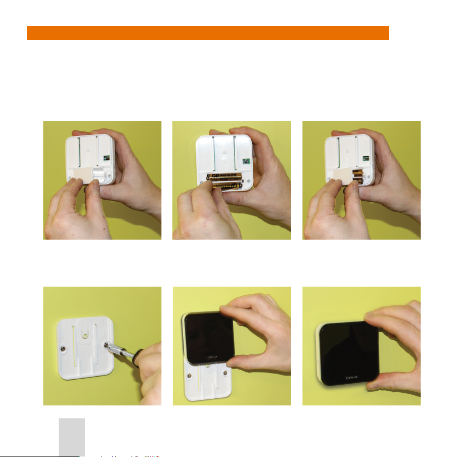
Battery Installation or Replacement
1. To install or replace the batteries in the iT500 Thermostat, remove the battery cover from the base of the
iT500 Thermostat.
Note: Dispose of replaced batteries at a suitable recycling facility.
2. With the unit face down, insert the rst battery supplied into the right hand side of the base of the iT500
Thermostat.
iT500 User Reference Manual
66

3. Insert the second battery supplied into the left hand side of the base of the iT500 Thermostat.
4. Ensure the batteries are tted securely in the base of the iT500 Thermostat.
5. Replace the battery cover to the base of the iT500 Thermostat.
Note: The serial number of the iT500 Thermostat is on a label in the back of the battery compartment.
Resetting the iT500TR Thermostat
To return your iT500 Thermostat to its factory settings insert a paper clip, or similar blunt object, into the hole
at the bottom of the stand socket on the back of the unit, for XX seconds.
<XX - HOW LONG? HAS BEEN TRIED FOR 30 SECONDS - DOES NOT REVERT TO DEFAULT>
Note: If the stand is attached this must be removed to access the reset hole.
iT500 User Reference Manual
67

Firmware Updates
Devices LogoutHome
My Account
Devices LogoutHome
My Account
The rmware used by iT500 Thermostats is periodically updated by SALUS. To install these updates on your
iT500, go to the website and follow the onscreen instructions. For example:
The rmware on your unit will then be updated using OTA (Over The Air) technology.
The display will ash 1, 2, 3, 4, 5, 6 to show that an update is in progress, starting with 1 and rising to 6:
Warning: While the update is in progres, do not exit the webpage or disconnect the device,
as this will cancel the update.
DO NOT: Remove the batteries while the update is in progress as this will result in your iT500TR
being permanantly unusable.
iT500 User Reference Manual
68

TECHNICAL SPECIFICATIONS
Operating Environment
Temperature 0 - 50 °C
Humidity 5 - 95%
iT500 Central Thermostat
Weight 170 g (not including batteries)
Dimensions 128.0 x 93.0 x 28.2mm
Mounting Flat surface or wall
Channels x 2 - Central Heating 1 and Central Heating 2
RF Module Two way 868MHz 1 Way Receiver / Transmitter
OTA Over the Air technology
Date Format Days of the week 1-2-3-4-5-6-7
Time Format 12hr/24hr – 12hr is the default
Temperature °C/°F – the default is °C
Heat Control Heating mode is default
Programmer Heating Zones 1 and 2: whole week, week-
Power Supply 2 o AA alkaline batteries LR6
/ Hot Water
-0.25 to 45.25°C range, resolution is 0.25°C
1 – 9°C Frost Protection range
In Cooling mode Frost Protection is disabled
days only, weekends only or individual days
selectable
Hot Water: On/O - days selectable as above
Frost Protection: always on
12 months life
Flashing low battery indicator
iT500 User Reference Manual
69

iT500RX Thermostat Receiver
Weight 210g
Dimensions 144.6mm x 99.5mm x 34.8mm
Mounting Flat surface
Channels x 2 - Heating Zone 1 and Heating Zone 2 / Hot
RF Module One way 868MHz Receiver
Power Supply x 2 AA alkaline batteries LR6
Water
30 meters minimum range
12 months life
Flashing low battery indicator
iTG500 Gateway
Weight 50g (not including adaptor)
Dimensions 91 x 38.5 x 25.5 mm
Mounting Flat surface
RF Module One way 868MHz Transmitter / Receiver
OTA Over the Air technology
Internet Connection RJ45 connector to router
Power Supply Input: 230VAC – 50Hz
30 meters minimum range
External Antenna
Output: 5VDC – 300mA
Cable: 1 meter (Black)
Plug: AC power
iT500 User Reference Manual
70

iT300 Temperature Sensor Transmitter
Weight 70 g (not including batteries)
Dimensions 75.5mm x 75.5 mm x 22.5 mm
Mounting Flat surface
Channels Transmits to Heating Zone 2 only
RF Module One way 868MHz Receiver
Power Supply 2 o AA alkaline batteries LR6
30 meters minimum range
12 months life
Flashing low battery indicator
iT500 User Reference Manual
71

Waste Electrical and Electronic Equipment Directive (WEEE Directive)
This symbol on the product or on its packaging indicates that this product should not be
treated as household waste. Instead it should be handed over to a suitable collection point
for the recycling of electrical and electronic equipment. By ensuring this product is disposed
of correctly, you will help prevent potential negative consequences for the environment and
human health, which could otherwise be caused by inappropriate waste handling of this
information about recycling of this product, please contact your local council oce, your household waste
disposal service or the shop where you purchased the product.
product. The recycling of materials will help to conserve natural resources. For more detailed
CE Certicate of Conformance
iT500 User Reference Manual
72

Warranty
SALUS Controls warrants that this product will be free from any defect in materials or workmanship, and
shall perform in accordance with its specication, for a period of two years from the date of installation.
SALUS Controls sole liability for breach of this warranty will be (at its option) to repair or replace the defective
product.
Customer Name: ...................................................................................................................................................................
Customer Address: ..............................................................................................................................................................
............................................................................... Post Code: ................................................................................................
Tel No: ........................................................ Email: .................................................................................................................
Engineer’s Company: ..........................................................................................................................................................
Tel No: ......................................................... Email: ................................................................................................................
Installation Date: ..................................................................................................................................................................
Engineer’s Name: ..................................................................................................................................................................
Engineer’s Signature: .........................................................................................................................................................
iT500 User Reference Manual
73

 Loading...