

Page 1
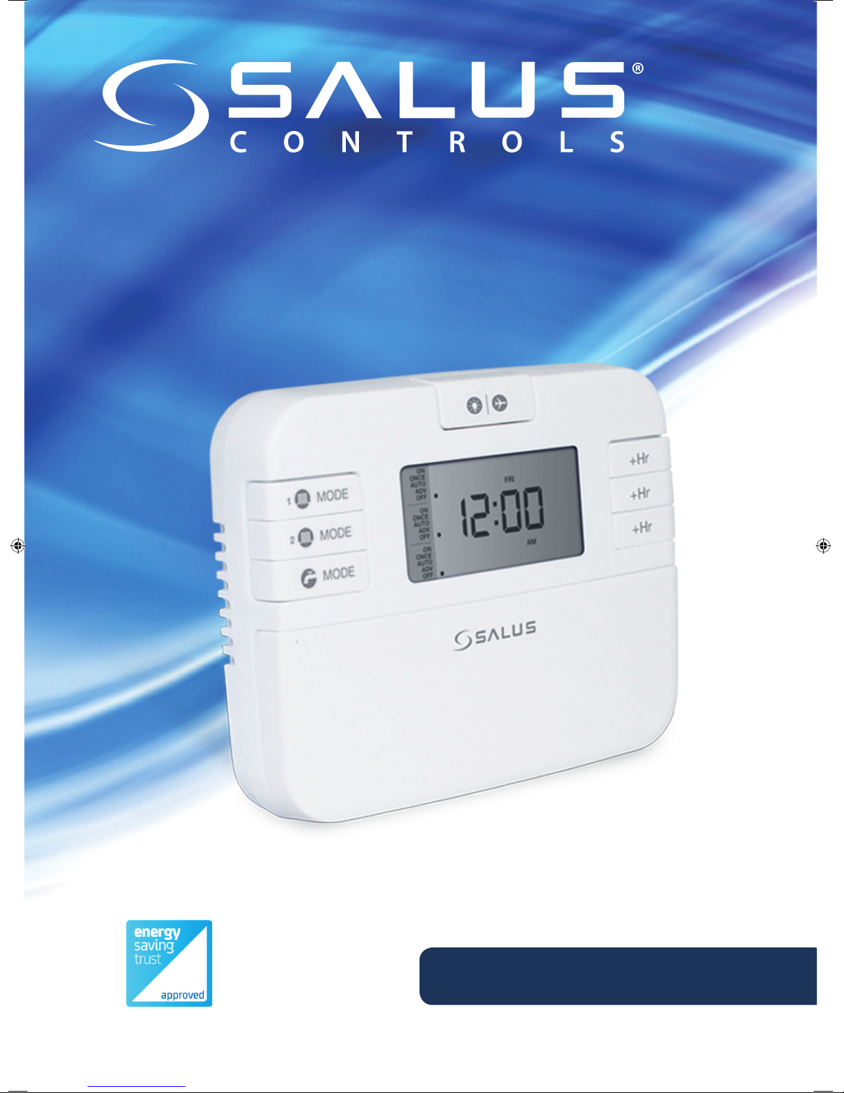
Model: EP310
Three channel programmable controller
Installation Manual
Page 2

Contents
Product Compliance ................................................................................................ 3
Safety Information .................................................................................................... 3
Box content ................................................................................................................... 3
Introduction .................................................................................................................. 4
Features ............................................................................................................................ 4
Installation ...................................................................................................................... 5
Button functions and LCD icons ...................................................................... 7
Operations ..................................................................................................................... 8
Functions ........................................................................................................................ 14
Factory Reset ................................................................................................................ 16
Technical Info ............................................................................................................... 17
Warranty .......................................................................................................................... 18
02 EP310 Installation Manual
Page 3
Product compliance
Installation
Jumper Settings
Input: 230V, 50Hz
Output: 3A/ switch terminal
1
EP110 Volt Free application only
EP110 - 230V Application Only
Note: Please remove red link wire for this application.
Terminal Description Backplate
N Mains Neutral
L Mains Live
1 Not Used
2 Not Used
3 Volt Free Connection
4 Volt Free Connection
Earth Parking
(no electrical connection)
NL1234
NL123456
Changes to the jumpers settings should only be made by the Engineer carrying
out the installation or other qualified person. The installer should select the jumper
positions required if changes need to be made to the factory default settings.
These jumpers are found on the rear of the controller.
EP110/ EP210/ EP310 Switching Bridges
Switch
Program
5-2 days programme or
24h programme
Fully pumped system(P*)
or gravity-fed hot water
system(G*)
System
Feature EP110/310 Settings
5-2
24H
24H
5-2
NA
NA
P
G
EP210 Settings
EP110/EP310 EP210
This product complies with the essential requirements and other relevant provisions of the following EU
Directives: 2014/30/EU, 2014/35/EU and 2011/65/EU. Please check www.saluslegal.com for the full information.
Safety Information
Use in accordance with the EU and national regulations. For indoor use only. Keep your device completely
dry. This product must be installed by a competent person and in accordance with all the EU and national
regulations.
Always isolate the AC Mains supply before installing or working on any components that
require 230 VAC 50Hz supply.
Box content
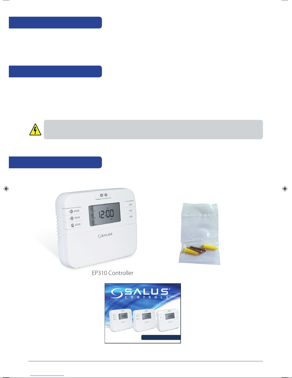
The box includes the EP310 controller, 2X screws and plugs and the Installer Manual-Quick Guide.
EP310 Controller
Model: EP110/EP210/EP310
2x screws and plugs
Quick Guide Installation
Installer Manual-Quick Guide
EP310 Installation Manual 03
Page 4

Introduction
The EP310 three channels programmable controller is a stylish wired timer that can be used for two central
heating zones and also for the hot water. Each output will control one zone, meaning that you can create
personalized schedules for each channel.
The EP310 programmable controller will switch ON and OFF your central heating system and/or hot water in
your home as needed. It works by controlling the heating boiler according to a series of programmed settings
that take effect at different times of the day.
By using the EP310 controller you can manage the commands sent to your boiler, motorized valves used in
your system or to your thermostat. You can set the EP310 programmable controller to a 12 or 24 hour format,
the Daylight saving Time (DST) being automatically enabled. The program mode is also selectable between
a 5-2 (Monday-Friday and Saturday-Sunday) or 24 hour format. For each of the programs you can create three
settings per day.
Being a complex programmable controller, the EP310 gives you the possibility to override your programs by
using the Boost function. This can be enabled for up to 9 hours.
For the periods when you are away you can use the Holiday function, which will turn off the relay. The Holiday
Mode can be set for a period of maximum 31 days.
When connected to a system with a non-programmable (digital) thermostat, it can turn the boiler ON or OFF
and control the heating and/or hot water in your system in a programmed manner.
The heating system and the hot water will be controlled with the EP310, meaning that this will send the
command of turning the relay on or off when needed, according to the programs created.
The EP310 programmable controller does not detect or adjust the temperature in your house, it is just sending
the commands to the boiler, motorized valve or the thermostat to turn ON or OFF the relay, depending on the
program settings.
The programs can be set individually for each channel, or, you can program them together if you want your
heating and hot water to be controlled in a coordinated manner.
04 EP310 Installation Manual
Page 5
Features
• Three Channel Programmer for Central Heater and Hot Water
• 12 or 24 hour clock format
• 5+2 or 24 h individual programs with 3 settings per day
• Boost function
• Holiday function
• Advance function
• Memory backup
Installation
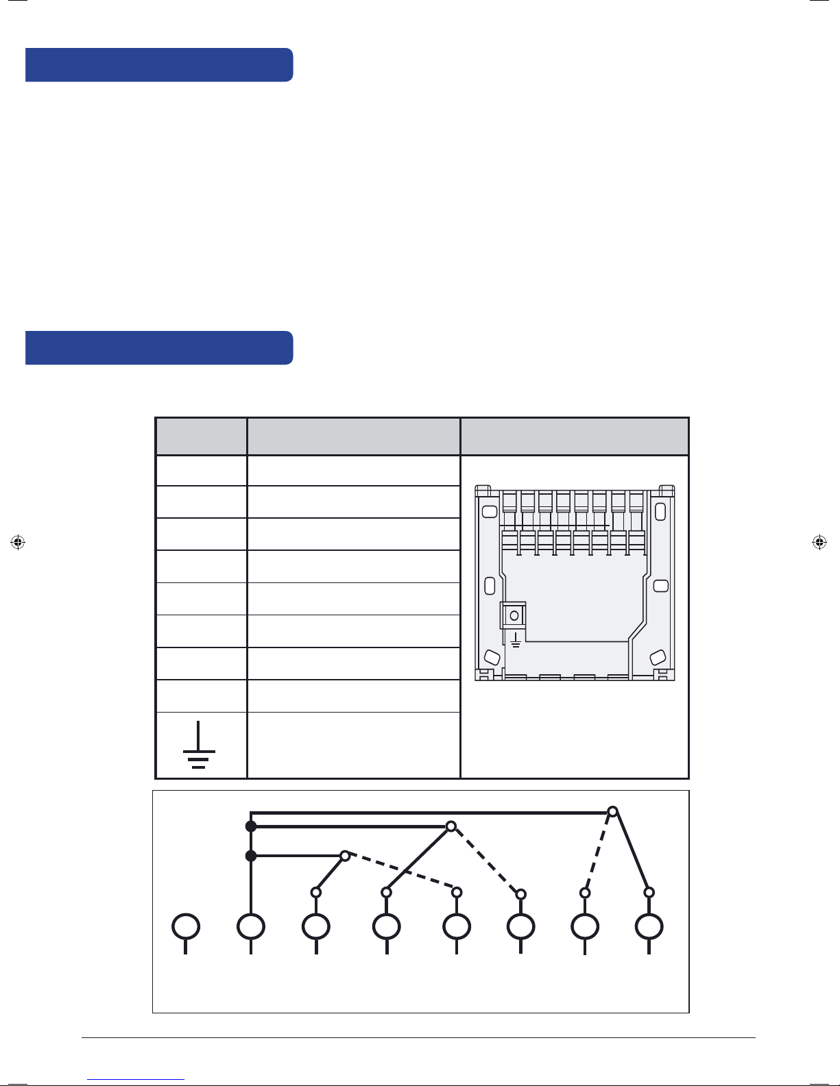
Wiring and terminal description
Terminal Description Backplate
N Mains Neutral
L Mains Live
1 Hot Water O
2 Central Heating O
3 Hot Water On
4 Central Heating 1 On
5 Central Heating 2 On
6 Central Heating 2 O
Earth Parking
(no electrical connection)
N L
N L HW CH1 HW
1
(o) (o)
2
3 4 5 6
CH1
(on) (on) (on)
CH2
EP310 Installation Manual 05
CH2
(o)
Page 6
Wall mounting
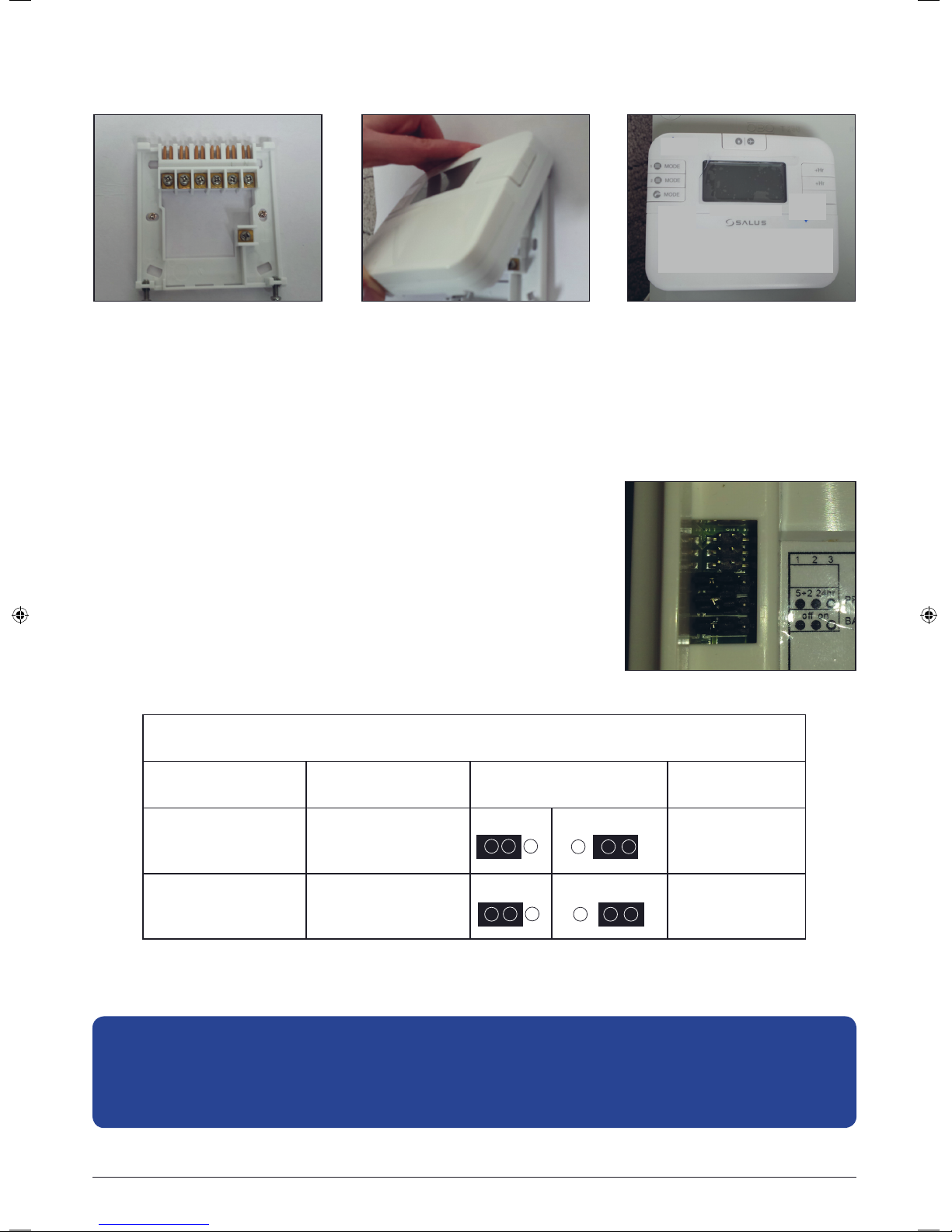
Fix the backplate to the wall. Align the front housing
at the top edge.
Jumper settings
The jumpers are found on the rear of your controller and can be used to
change the settings for the program type or internal backup memory
battery. If you want to change the position of your jumpers, please
note that you will need to reset your device. The default position for the
jumpers set a 5+2 program type and keep the internal backup battery off.
EP310 Switching Bridges
Switch Feature Setting Default
Fit the front housing.
Press lightly.
Program 5-2 days program or
Memory Backup Disable/enable the
Note: Changes to the jumper settings should only be made by the engineer carrying out the installation
or another qualified person. The installer should select the jumper positions required if changes need to
be made to the factory default settings. These jumpers are found on the rear of the controller.
06 EP310 Installation Manual
24h program
internal backup
battery
5-2 24H 5-2 days program
OFF ON Internal backup
battery disabled
Page 7
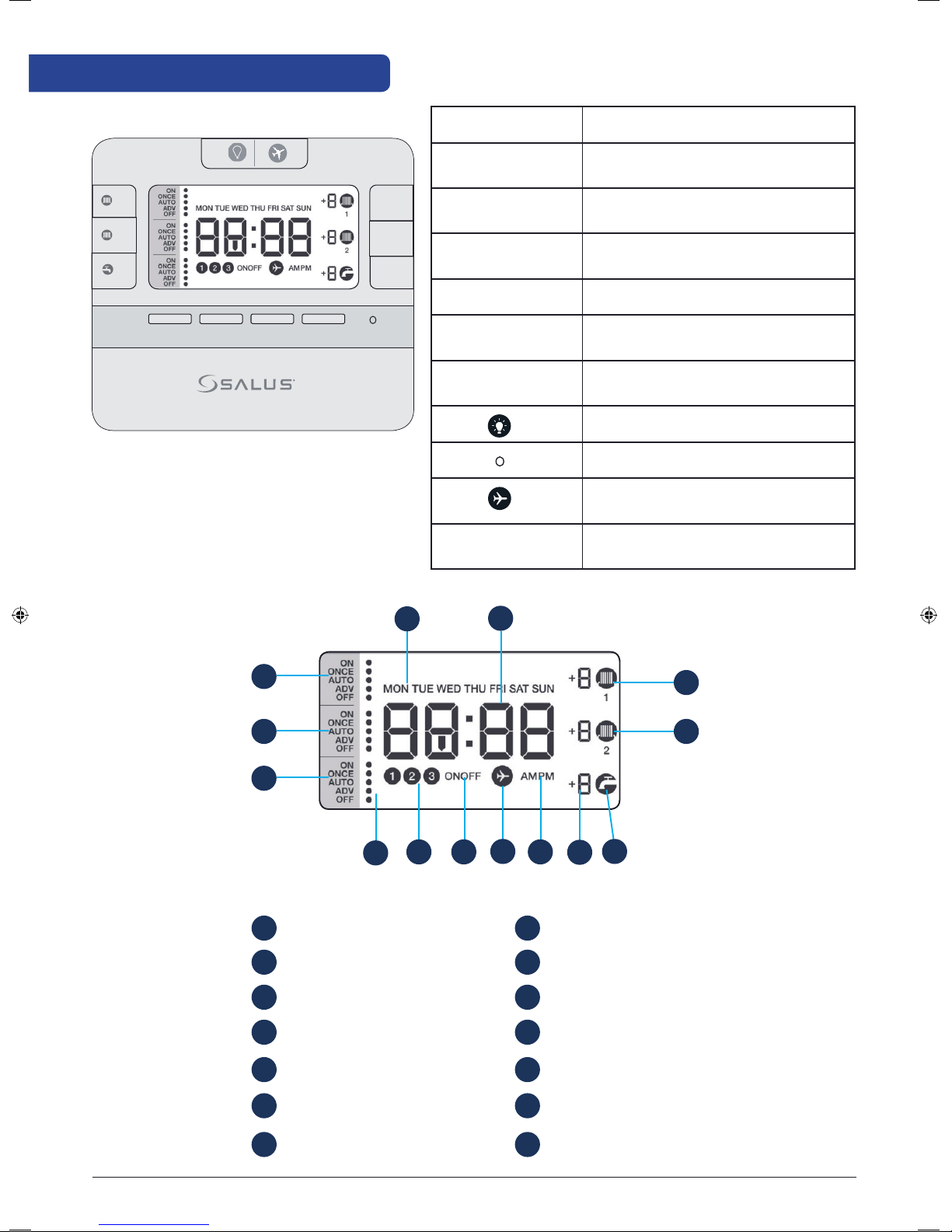
Button functions and LCD icons
1
MODE
2
MODE
MODE
<
<
SELECT SET
+Hr
+Hr
+Hr
Key Function
Mode Press to select ON/ONCE/AUTO/
ADV/OFF.
+1Hr Press to enter/cancel Boost override
function by setting Boost hours.
Select Press to select the setting of clock/
date/week day, etc.
Set Press to confirm the setting.
Up arrow Press to increase clock/day, press and
hold to enter fast advance.
Down arrow Press to decrease clock/day, press
and hold to enter fast advance.
Press to activate backlight.
Hardware reset.
Press and hold button for 3 seconds
to activate Holiday mode.
Select + Set Press and hold buttons to enter clock
setting mode.
14
13
12
1
Days of the week
2
Clock
3
Heating zone 1 On
4
Heating zone 2 On
Hot water On
5
11
1
2
3
4
8
910
7
8
Holiday Mode
9
DST On/Off
10
Program number
11
Mode Indicator
Hot Water panel
12
5
6
Boost hours
6
AM/PM
7
Heating Zone 2 panel
13
Heating Zone 1 panel
14
EP310 Installation Manual 07
Page 8
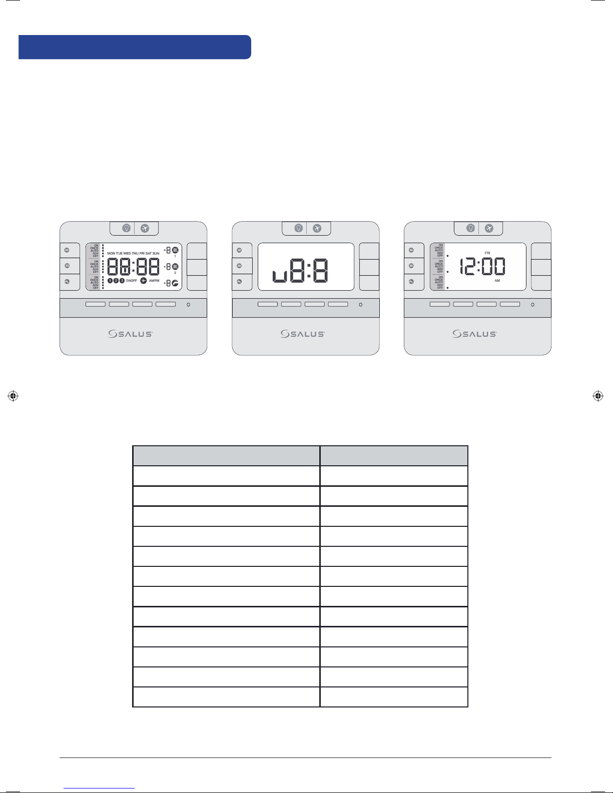
Operations
Initial power up
After power up or after RESET is pressed, the programmer is reset to factory default settings. During system
reset, all LCD icons and segments are turned on for 2 seconds and all keys are blocked. After 2 seconds and all
keys are released, the programmer is initialized. First, the software version is shown, after that, the typical reset
display is shown. The time should be 12:00am.
1
MODE
2
MODE
MODE
<
<
Default settings
SELECT SET
1
+Hr
+Hr
+Hr
MODE
2
MODE
MODE
<
<
SELECT SET
+Hr
+Hr
+Hr
1
MODE
2
MODE
MODE
Function Status after Reset
Operation Mode Normal mode
Clock 12:00 AM
AM/PM indicator AM
Date January 1, 2016
+Hr
+Hr
+Hr
<
<
SELECT SET
Daylight Saving Time(DST) On
Program Factory default 5+2
Program Number indicator Off
SET indicator Off
PROG indicator Off
Mode indicator(s) “Off“
Output Relay Off
CH/HW indicator(s) Off
08 EP310 Installation Manual
Page 9
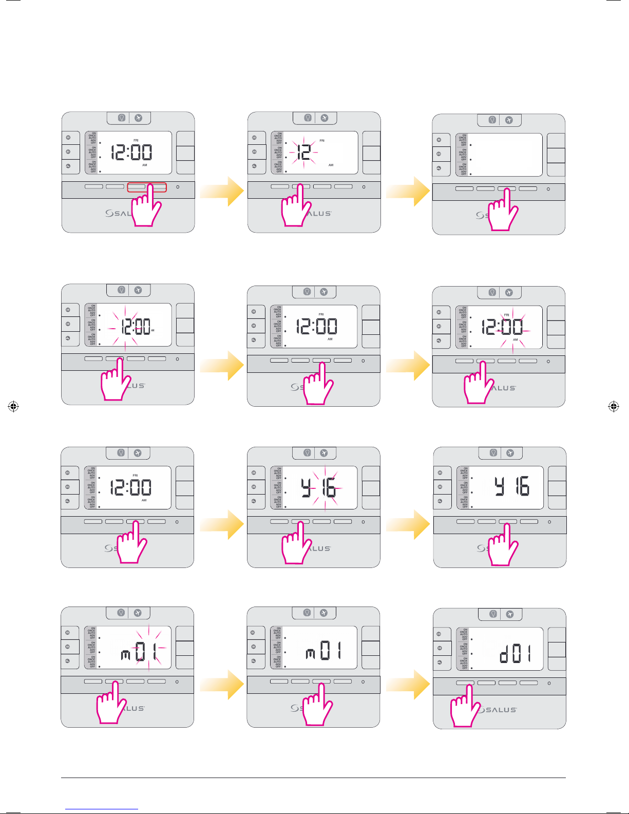
Setting time and date
The first thing you will have to do is to set the time and date on your controller. First you will need to set up
the time and then the date. To enter clock setting mode, press and hold Select and Set buttons for 3 seconds.
Please follow the instructions below.
1
MODE
2
MODE
MODE
<
<
SELECT SET
3 sec
3 sec
Press and hold the indicated
buttons together for 3 sec.
1
MODE
2
MODE
MODE
<
<
SELECT SET
Press Up or Down
to set the hour.
1
+Hr
+Hr
+Hr
MODE
2
MODE
MODE
<
12 hr
SELECT SET
<
Choose your clock format
+Hr
+Hr
+Hr
1
MODE
2
MODE
MODE
<
12 hr
SELECT SET
<
+Hr
+Hr
+Hr
Press Select to confirm.
Press Up/Down arrow
for 12/24 hr format.
+Hr
+Hr
+Hr
1
MODE
2
MODE
MODE
<
<
SELECT SET
Press Select to confirm.
+Hr
+Hr
+Hr
1
MODE
2
MODE
MODE
<
<
SELECT SET
+Hr
+Hr
+Hr
Press Up or Down
to set the minutes.
1
MODE
2
MODE
MODE
<
<
SELECT SET
Press Select to confirm.
1
MODE
2
MODE
MODE
<
<
SELECT SET
Press Up or Down
to set the month.
1
+Hr
+Hr
+Hr
MODE
2
MODE
MODE
<
<
SELECT SET
+Hr
+Hr
+Hr
Press Up or Down
1
MODE
2
MODE
MODE
<
<
SELECT SET
Press Select to confirm.
+Hr
+Hr
+Hr
to set the year.
1
+Hr
+Hr
+Hr
MODE
2
MODE
MODE
<
<
SELECT SET
Press Select to confirm. Press Up or Down
+Hr
+Hr
+Hr
1
MODE
2
MODE
MODE
<
<
SELECT SET
+Hr
+Hr
+Hr
to set the date.
EP310 Installation Manual 09
Page 10
1
MODE
2
MODE
MODE
+Hr
+Hr
+Hr
1
MODE
2
MODE
MODE
+Hr
+Hr
+Hr
1
MODE
2
MODE
MODE
+Hr
+Hr
+Hr
<
<
SELECT SET
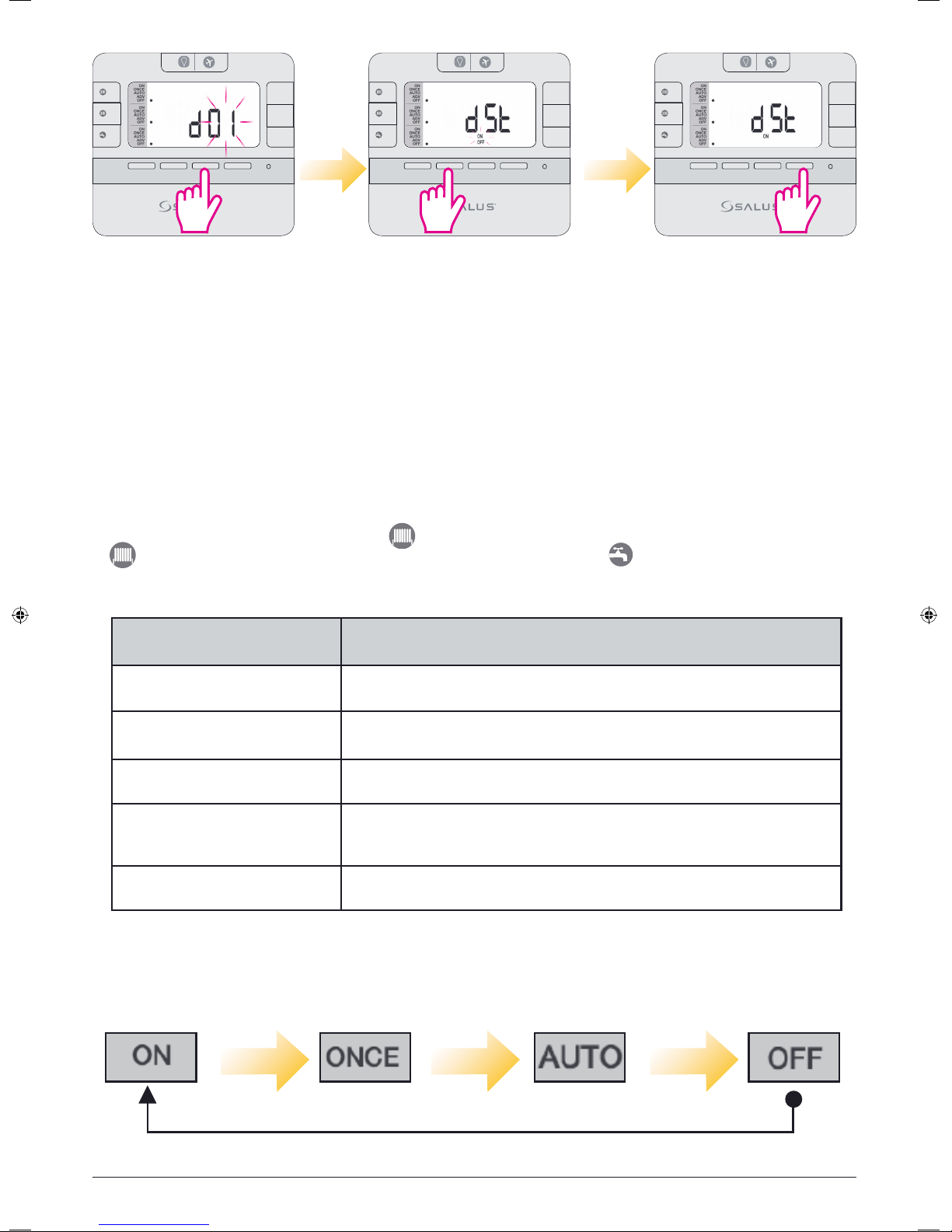
Press Select to confirm. Press Up or Down to
<
<
SELECT SET
select DST on/off.
<
<
SELECT SET
Press Set to confirm and
exit to normal mode.
When Daylight saving time is enabled, the clock will automatically change from Greenwich Mean Time (GMT)
to British Summer Time (BST) on the last Sunday in March. The clock will automatically change back to GMT
on the last Sunday in October.
Operating Modes
EP310 can operate in 5 different modes, applicable to CH1, CH2, HW or CH+HW. The operations modes are
the same for CH and HW and can be set individually, or together. If you want to choose the mode for the
CH1(central heating in zone 1), press the 1 Mode key. To control the central heating in zone 2 (CH2) press
2 Mode key. If you want to choose the mode for the HW, press the Mode Key. EP310 is a complex
controller that can control 2 different heating zones and the hot water separately.
Operation Mode Function
ON Continuously on
ONCE On for 1 period a day, from Program 1 ON to Program 3 OFF
AUTO Automatic program control
When device is in Auto or Once mode, press the MODE button for 3 sec for
ADV
OFF Continuously off
For activating the functions described above, press the MODE button. The operating mode is cycled in the
below sequence:
selecting Advance (ADV). This will move the unit into the next program. When
the ADV function ends the device will return to normal program.
10 EP310 Installation Manual
Page 11
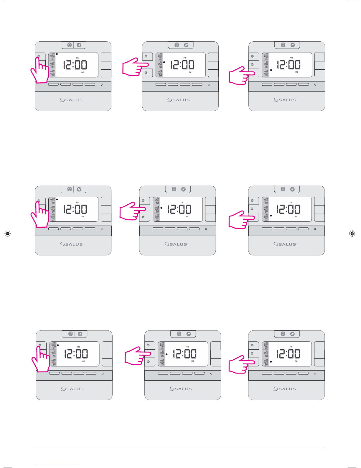
ON Mode
1
MODE
2
MODE
MODE
<
<
SELECT SET
+Hr
+Hr
+Hr
3 sec
Press for CH1. Press for HW.
1
MODE
2
MODE
MODE
<
<
SELECT SET
+Hr
+Hr
+Hr
3 sec
1
MODE
2
MODE
MODE
<
<
SELECT SET
+Hr
+Hr
+Hr
3 sec
Press for CH2.
Pressing the Mode key once activates the ON Mode. In ON mode, the controller gives the boiler the ON
command, so the heating or/and the hot water will run continuously.
Once Mode
1
MODE
2
MODE
MODE
<
<
SELECT SET
+Hr
+Hr
+Hr
1
MODE
2
MODE
MODE
<
<
SELECT SET
+Hr
+Hr
+Hr
1
MODE
2
MODE
MODE
<
<
SELECT SET
+Hr
+Hr
+Hr
3 sec
Press for CH1. Press for HW.
Press for CH2.
3 sec
3 sec
Pressing the Mode key twice activates the ONCE Mode. In ONCE mode, the controller gives the boiler the
command to run only for one period per day (from program 1 ON to program 3 OFF)
Auto Mode
1
MODE
2
MODE
MODE
<
<
SELECT SET
+Hr
+Hr
+Hr
3 sec
Press for CH1. Press for HW.
1
MODE
2
MODE
MODE
<
<
SELECT SET
+Hr
+Hr
+Hr
3 sec
1
MODE
2
MODE
MODE
<
<
SELECT SET
+Hr
+Hr
+Hr
3 sec
Press for CH2.
Pressing the Mode key 3 times activates the AUTO. In AUTO mode, the controller gives the boiler the ON/OFF
command depending on your schedule.
EP310 Installation Manual 11
Page 12
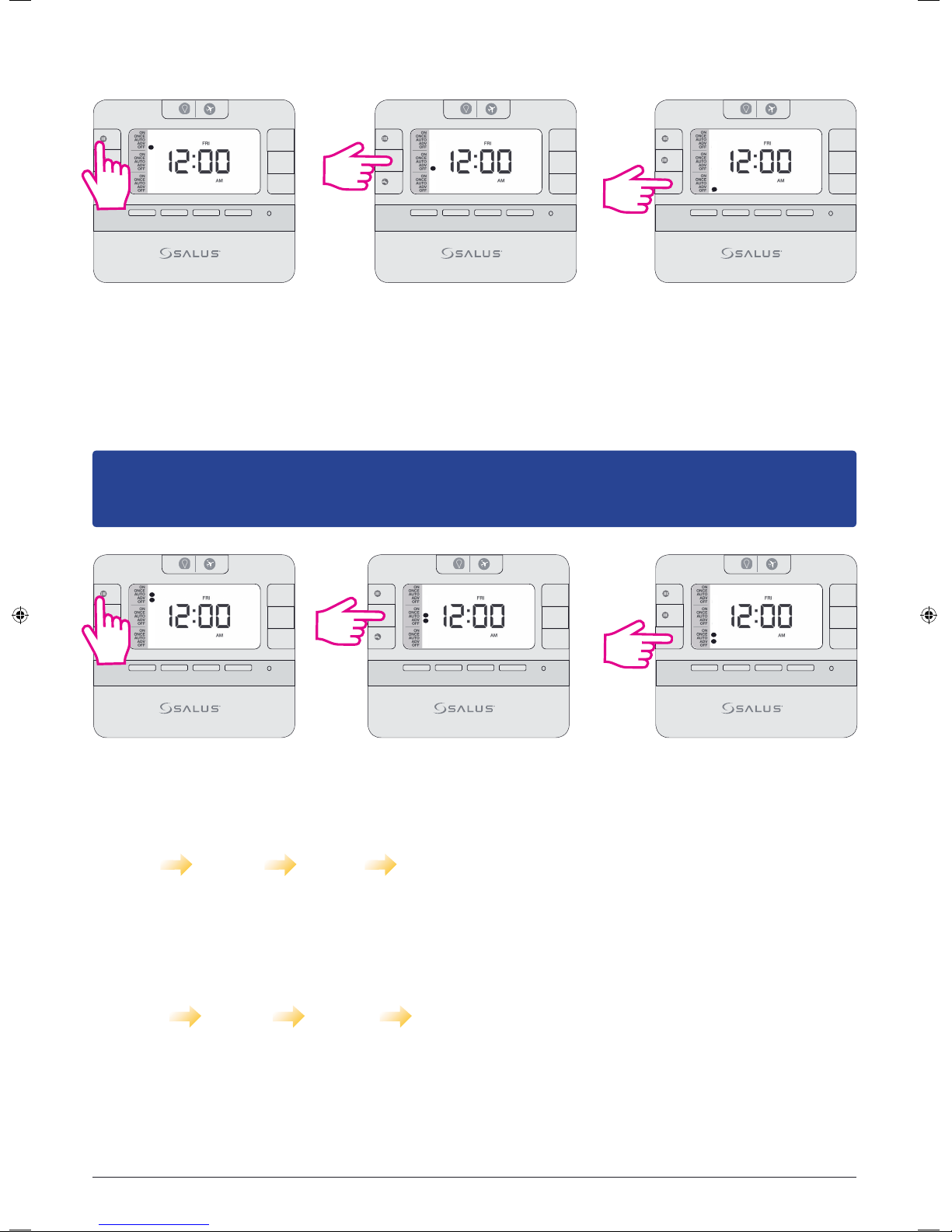
OFF Mode
1
MODE
2
MODE
MODE
<
<
SELECT SET
+Hr
+Hr
+Hr
3 sec
Press for CH1.
1
MODE
2
MODE
MODE
<
<
SELECT SET
+Hr
+Hr
+Hr
3 sec
Press for CH2.
1
MODE
2
MODE
MODE
<
<
SELECT SET
+Hr
+Hr
+Hr
3 sec
Press for HW.
Pressing the Mode key 4 times activates the OFF Mode. In OFF mode, the controller gives the boiler the OFF
command, so the heating or the hot water will be turned off.
ADV Mode
Note: In ONCE or AUTO mode, by long pressing the MODE button, the controller will switch automatically
to ADV. You can cancel the ADV by long pressing the MODE key. The device will then return to ONCE or
AUTO mode. You can’t select ADV by pressing Mode key.
1
MODE
2
MODE
MODE
<
<
SELECT SET
+Hr
+Hr
+Hr
3 sec
Press for CH1. Press for HW.
1
MODE
2
MODE
MODE
<
<
SELECT SET
+Hr
+Hr
+Hr
3 sec
1
MODE
2
MODE
MODE
<
<
SELECT SET
+Hr
+Hr
+Hr
3 sec
Press for CH2.
When in Auto mode selecting ADV, the controller will simply toggle the current auto setting (ON or OFF).
For example, if the current program is set as:
08:00 ON 09:00 OFF 10:00 ON 11:00 OFF
Selecting ADV between 8:00 and 8:59 will change the output to OFF, from 9:00 onwards back to AUTO (which
is also OFF). Selecting ADV between 9:00 and 09:59 will change the output to ON, from 10:00 onwards back to
AUTO (which is also ON). If the ADV puts the relay ON then the boost would apply immediately at the next OFF
change, if the ADV put the relay OFF then the boost would apply immediately and turn the relay ON.
08:00 OFF 10:00 ON 12:00 OFF 14:00 ON
If ADV occurs at 08:30 and the relay is ON from 08:30 to 12:00. During this period, if at 08:45 +1Hr (Boost) is
pressed, the relay will be ON from 08:30 to 12:00. Boost is applied immediately from 08:45 to 09:45. If ADV
occurred at 10:30 the relay will be ON from 10:00, OFF from 10:30 (ADV) to 14:00 if no +1Hr Override. During
ADV, if at 10:45 +1Hr (Boost) is pressed relay ON again at 10:45 (boost starts), OFF at 11:45 (Boost ends) until
ends at 14:00, then ON again at 14:00.
10 EP310 Installation Manual
Page 13
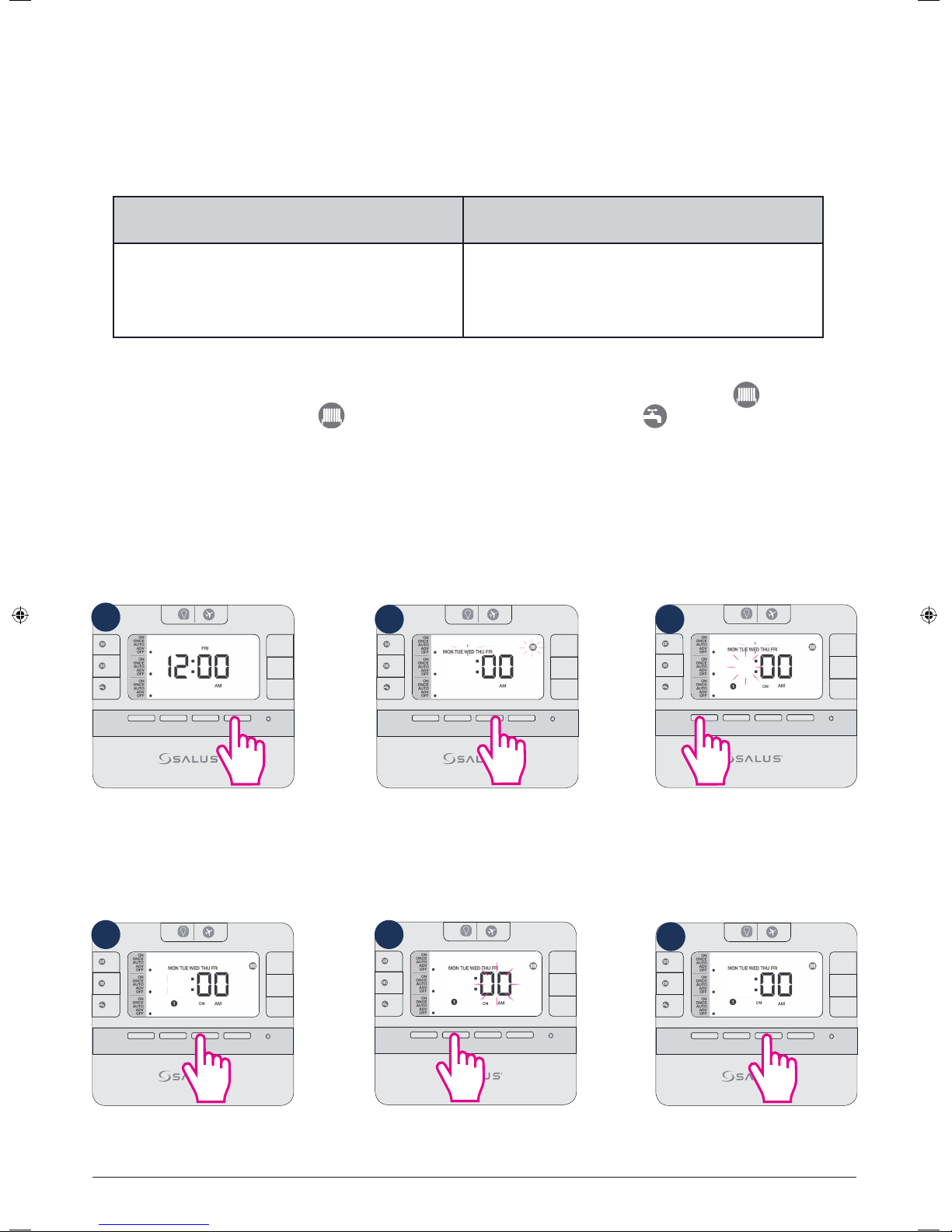
Programming the EP310
2 types of programs can be set:
• 5+2 (Mon to Fri same and Sat, Sun same)
• Different programs for each 24h.
There are 3 different time sets for each day.
5-2 Days Program Individual Days Program
Weekdays
3 sets of time/channel
3 sets of time/channel
1 Day
Weekends
3 sets of time/channel
Total: 12 settings/week
Total: 63 settings/week
EP310 is a 3 channel controller, that gives the possibility to control both Central Heating in 2 different zones
and Hot Water. You can choose which one you would like to control, by simply pressing the 1 Mode key for
Central Heating in zone 1, the 2 Mode key for Central Heating in zone 2 or Mode key for hot Water, or
you can use them together, as by your needs. You can program the schedules for these outputs individually or
for the all 3. When you program them altogether, there will be the same program time for both CH1, CH2 and
the HW. If you choose to program them individually, you can have different program times for each.
5+2 Program
Programming CH1, CH2 and HW individually
1
1
MODE
2
MODE
MODE
<
<
SELECT SET
+Hr
+Hr
+Hr
2 3
1
MODE
2
MODE
MODE
6
<
<
SELECT SET
+Hr
+Hr
+Hr
1
MODE
2
MODE
MODE
6
<
<
SELECT SET
+Hr
+Hr
+Hr
Press Set to enter
setting programs.
4 5
1
MODE
2
MODE
MODE
6
<
<
SELECT SET
+Hr
+Hr
+Hr
Press Select.
The CH1 icon and Mon-Fr will start
flashing. Press Select.
1
MODE
2
MODE
MODE
6
<
<
SELECT SET
+Hr
+Hr
+Hr
Use up/down arrows
to select minutes.
The CH icon will go steady, the
program number will appear
and you will need to select a
start time for the CH program.
Use up/down arrows.
6
1
MODE
2
MODE
MODE
6
<
<
SELECT SET
+Hr
+Hr
+Hr
Press Select.
EP310 Installation Manual 13
Page 14
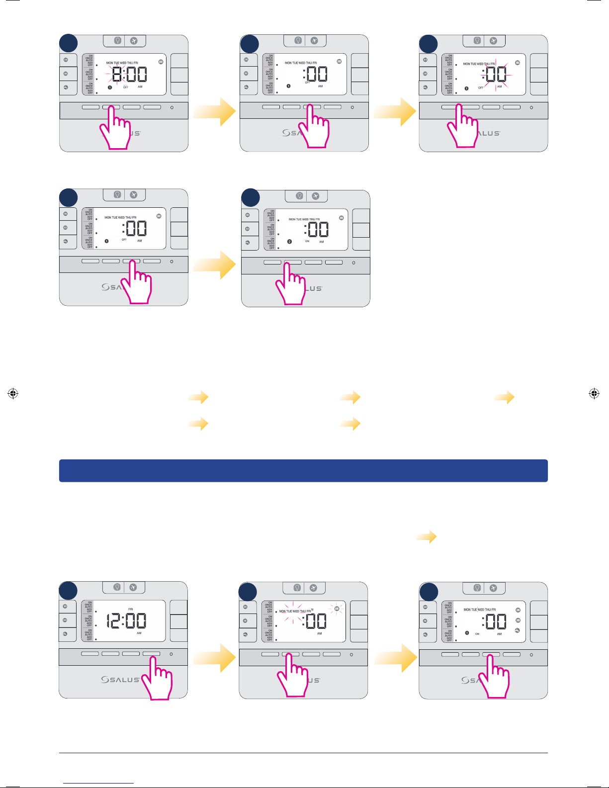
7
1
MODE
2
MODE
MODE
8
+Hr
+Hr
+Hr
8 9
1
MODE
2
MODE
MODE
8
+Hr
+Hr
+Hr
1
MODE
2
MODE
MODE
8
+Hr
+Hr
+Hr
<
<
Select an end time for
the first program.
10
1
MODE
2
MODE
MODE
8
<
<
SELECT SET
SELECT SET
<
<
SELECT SET
Press Select.
11
+Hr
+Hr
+Hr
1
MODE
2
MODE
MODE
8
<
<
SELECT SET
+Hr
+Hr
+Hr
Please continue by following the
same steps for program nr 2 and 3.
After you finish programming CH1
for weekdays, the controller will ask
you to do the same thing for the
CH2 and after that for the HW. You
<
<
SELECT SET
Use up/down arrows
to select minutes
.
can choose different or similar end/
start time.
Press Select.
Controller will now go to
program nr 2.
The sequences followed by the controller when programming CH1, CH2 and HW individually goes at
it follows:
Weekday CH1 (program 1-3) Weekday CH2 (program 1-3) Weekday HW (program 1-3)
Weekend CH1 (program 1-3) Weekend CH2 (program 1-3) Weekend HW (program 1-3) and all over
again.
Note: To save your settings and exit to home screen in normal mode, press Set at any time.
Programming CH1, CH2 and HW together
The programming principle is exactly the same, but you can only set the same Start/End time for the CH1, CH2
and HW. The programming sequence goes as it follows: Weekday CH1+CH2+HW Weekend CH1+CH2+HW
and all over again. To program them together, follow the steps:
1
1
MODE
2
MODE
MODE
<
<
SELECT SET
+Hr
+Hr
+Hr
2 3
1
MODE
2
MODE
MODE
6
<
<
SELECT SET
+Hr
+Hr
+Hr
1
MODE
2
MODE
MODE
6
<
<
SELECT SET
+Hr
+Hr
+Hr
Press Set to enter
setting programs.
14 EP310 Installation Manual
The CH1 icon and Mon-Fri
will start flashing. Press up
arrow 3 times.
All 3 icons will appear. Press Select
to start entering a start time for the
program and then follow the same
steps as above from 3-11.
Page 15
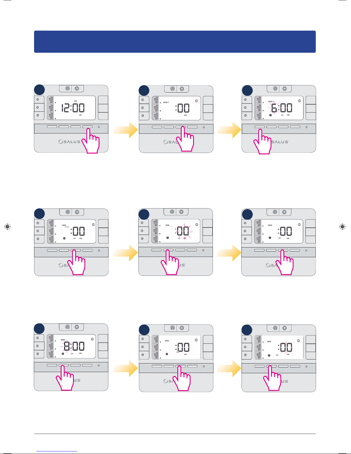
Setting dierent programs for each 24h
Note: Don’t forget to move the jumpers to 24h in order to have the individual program active. After
that please follow the same instructions as for the 5-2 days program.
Programming CH1, CH2 and HW individually
1
1
MODE
2
MODE
MODE
<
Press Set to enter
setting programs.
4
1
MODE
2
MODE
MODE
<
2 3
<
SELECT SET
+Hr
+Hr
+Hr
1
MODE
2
MODE
MODE
6
<
<
SELECT SET
+Hr
+Hr
+Hr
The CH1 icon and the Mon
will start flashing. Tap Select.
1
MODE
2
MODE
MODE
6
<
<
The CH icon will go steady, the
program number will appear
and you will need to select a
start time for the CH program.
Use up/down arrows.
5 6
1
+Hr
6 6 6
SELECT SET
<
+Hr
+Hr
MODE
2
MODE
MODE
<
<
SELECT SET
+Hr
+Hr
+Hr
1
MODE
2
MODE
MODE
<
<
+Hr
+Hr
+Hr
SELECT SET
+Hr
+Hr
+Hr
SELECT SET
Press Select.
7
1
MODE
2
MODE
MODE
8
<
<
SELECT SET
+Hr
+Hr
+Hr
Select an end time for
the first program.
Use up/down arrows
to select minutes.
8
1
MODE
2
MODE
MODE
8 8
<
<
Press Select.
SELECT SET
Press Select.
9
+Hr
+Hr
+Hr
1
MODE
2
MODE
MODE
<
<
SELECT SET
+Hr
+Hr
+Hr
Use up/down arrows
to select minutes.
EP310 Installation Manual 15
Page 16
10
1
2
11
1
MODE
MODE
MODE
8
<
<
SELECT SET
+Hr
+Hr
+Hr
MODE
2
MODE
MODE
8
<
<
SELECT SET
+Hr
+Hr
+Hr
Please continue by following the
same steps for program nr 2 and
3. After you finish programming
CH1 for Monday, the controller
will ask you to do the same thing
for the CH2 and after that for the
HW. Then it will go to Tuesday,
Wednesday etc. You can choose
different or similar end/start time.
Press Select.
Controller will now go to
program nr 2.
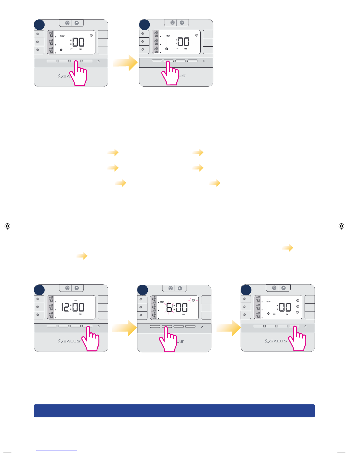
The sequences followed by the controller when programming CH1, CH2 and HW individually goes at
it follows:
Monday CH1 (program 1-3) Monday CH2 (program 1-3) Monday HW (program 1-3)
Tuesday CH1 (program 1-3) Tuesday CH2 (program 1-3) Tuesday HW (program 1-3)
Wednesday CH1 (program 1-3) Wednesday CH2 (program 1-3) Wednesday HW (program 1-3) etc
Programming CH1, CH2 and HW together
The programming principle is exactly the same, but you can only set the same Start/End time for the
CH1, CH2 and HW. The programming sequence goes as it follows: Monday CH1+CH2+HW Tuesday
CH1+CH2+HW Wednesday CH1+CH2+HW etc and all over again. To program them together,
follow the steps:
1 2 3
1
MODE
2
MODE
MODE
<
Press Set to enter
setting programs
<
SELECT SET
+Hr
+Hr
+Hr
1
MODE
2
MODE
MODE
6
<
<
SELECT SET
+Hr
+Hr
+Hr
The CH1 icon and Mon-Fri
will start flashing. Press up
arrow 3 times.
MODE
2
MODE
MODE
6
<
<
SELECT SET
All 3 icons will appear. Press
Select to start entering a start
time for the program and then
+Hr
+Hr
+Hr
1
follow the same steps as
above from 3-11
Note: To save your settings and exit to home screen in normal mode, press Set at any time.
16 EP310 Installation Manual
Page 17
Functions
Temporary Override
Boost Override (+1Hr override)
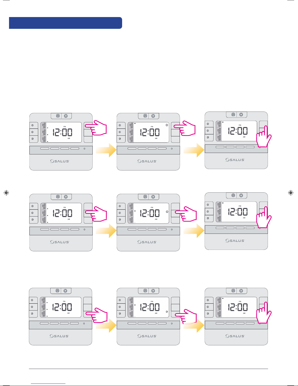
Boost Override (+1Hr override) is available in ONCE/AUTO/OFF modes. Boost mode can be activated even in
ADV mode. When boost mode is activated , ADV is canceled. Press +1Hr at current mode to activate the Boost
Override (+1Hr override) setting mode. Boost mode increases the time of the active program by 1-9 hours.
The new setting hour “+x” (x=last boost hour+1 hour) is displayed. Subsequent press of +1Hr will increase
the duration by 1 hour. Maximum duration is 9 hours. If the number rolls back to blank, this will disable
the Boost Override.
Boost Override (+1Hr override) for CH1 and CH2
1
1
MODE
2
MODE
MODE
<
<
SELECT SET
+Hr
+Hr
+Hr
1
MODE
2
MODE
MODE
<
<
SELECT SET
+Hr
+1
+Hr
+Hr
MODE
2
MODE
MODE
<
<
SELECT SET
+Hr
+Hr
+Hr
Press +1Hr to enter Boost
override for CH1.
1
MODE
2
MODE
MODE
<
<
SELECT SET
Press +1Hr to enter Boost
override for CH2.
+Hr
+Hr
+Hr
The number of boost hours for
CH1 will be displayed.
1
MODE
2
MODE
MODE
The number of boost hours for
CH2 will be displayed.
Boost Override (+1Hr override) for Hot Water
1
MODE
2
MODE
MODE
<
<
SELECT SET
+Hr
+Hr
+Hr
1
MODE
2
MODE
MODE
To exit boost override, press
mode button until number
+x disappears.
1
+Hr
+Hr
+1
+Hr
<
<
SELECT SET
MODE
2
MODE
MODE
<
<
SELECT SET
+Hr
+Hr
+Hr
To exit boost override, press
mode button until number
+x disappears.
1
+Hr
+Hr
+Hr
+1
<
<
SELECT SET
MODE
2
MODE
MODE
<
<
SELECT SET
+Hr
+Hr
+Hr
Press +1Hr to enter Boost
override for CH2.
The number of boost hours for
CH2 will be displayed.
To exit boost override, press
mode button until number
+x disappears.
EP310 Installation Manual 17
Page 18
ADV Override
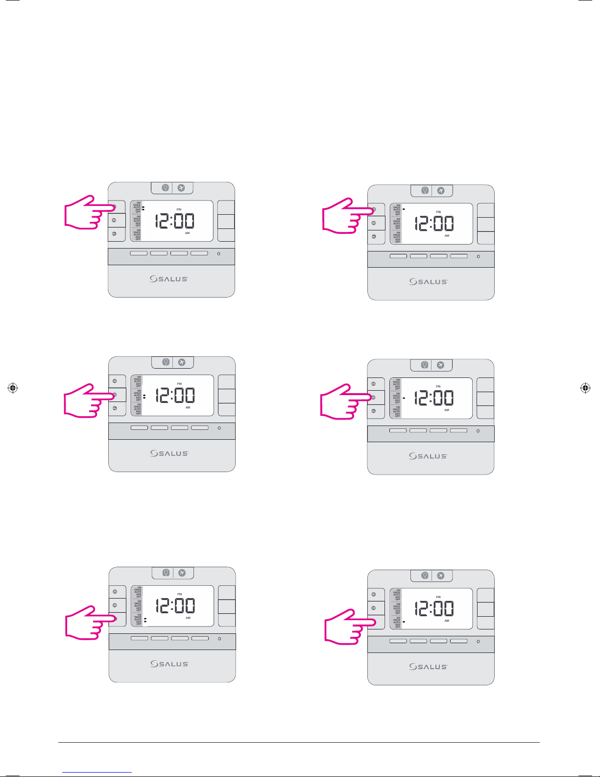
ADV only works in AUTO or ONCE mode. During ADV, press MODE once to cancel ADV and go back to AUTO
/ONCE mode after LCD backlight is turned off. +1Hr override and ADV cannot co-exist in same channel.
During ADV mode, when +1Hr is pressed, override mode will cancel ADV mode then change to Boost mode.
If +1Hr override (Boost) is running, then ADV is selected, ADV will be activated and the previous +1Hr override
will be cancelled.
ADV Override for Heating CH1, CH2
1
3 sec
MODE
2
MODE
MODE
<
<
SELECT SET
+Hr
+Hr
+Hr
1
MODE
2
MODE
MODE
<
<
SELECT SET
+Hr
+Hr
+Hr
Long press Mode while in Auto
or Once to enter ADV override
Mode for CH1.
1
MODE
2
3 sec
MODE
MODE
<
<
SELECT SET
Long press Mode while in Auto
or Once to enter ADV override
Mode for CH2.
ADV Override for Hot Water
1
MODE
2
MODE
3 sec
MODE
<
<
SELECT SET
Short press Mode while in ADV
to exit mode for CH1 back to
auto or Once.
+Hr
+Hr
+Hr
1
MODE
2
MODE
MODE
<
<
SELECT SET
+Hr
+Hr
+Hr
Short press Mode while in ADV
to exit mode for CH2 back to
auto or Once.
+Hr
+Hr
+Hr
1
MODE
2
MODE
MODE
<
<
SELECT SET
+Hr
+Hr
+Hr
Long press Mode while in
Auto or Once to enter
ADV override Mode.
18 EP310 Installation Manual
Short press Mode while in
ADV to exit mode back
to auto or Once.
Page 19
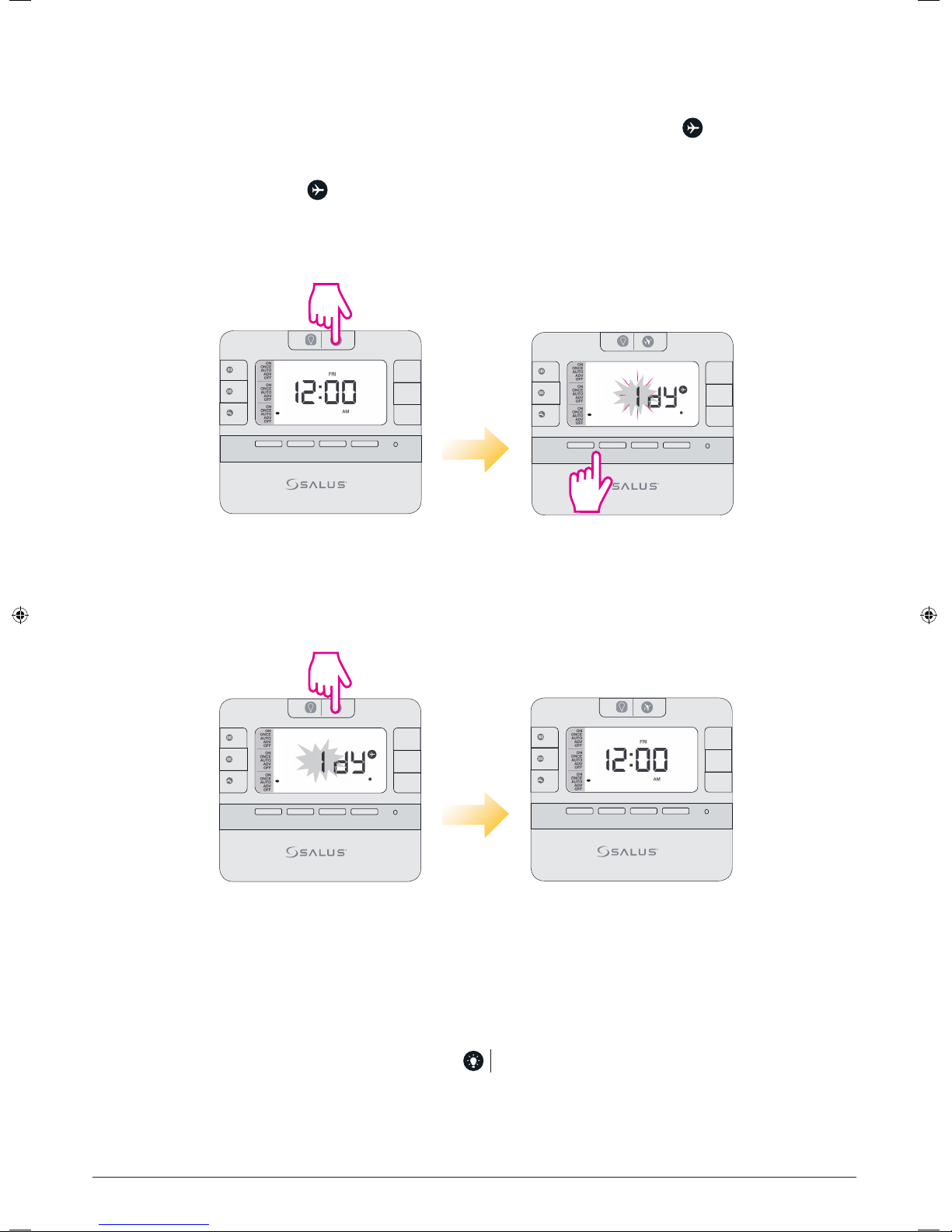
Holiday Override
During the period of holiday override, relay should be always Off. Press and hold at current mode
for 3 seconds to activate the Holiday Override setting mode. The plane icon will be displayed on the LCD and
the user’s only option will be to set the number of holiday days (up to 31). To exit Holiday Override and turn
On the relay, long press the key.
Enter Holiday Mode
3 sec
1
MODE
2
MODE
MODE
<
<
SELECT SET
+Hr
+Hr
+Hr
1
MODE
2
MODE
MODE
<
<
SELECT SET
+Hr
+Hr
+Hr
Exit Holiday Mode
LCD Backlight
Press for 3 seconds
Press Up/Down keys to select days
3 sec
1
1
MODE
2
MODE
MODE
<
<
SELECT SET
+Hr
+Hr
+Hr
MODE
2
MODE
MODE
<
Press for 3 seconds Controller in current mode
<
+Hr
+Hr
+Hr
SELECT SET
If AC is powered, LCD backlight is activated when or any key is pressed. The backlight will be turned
off in 15 seconds after all keys are released.
EP310 Installation Manual 19
Page 20
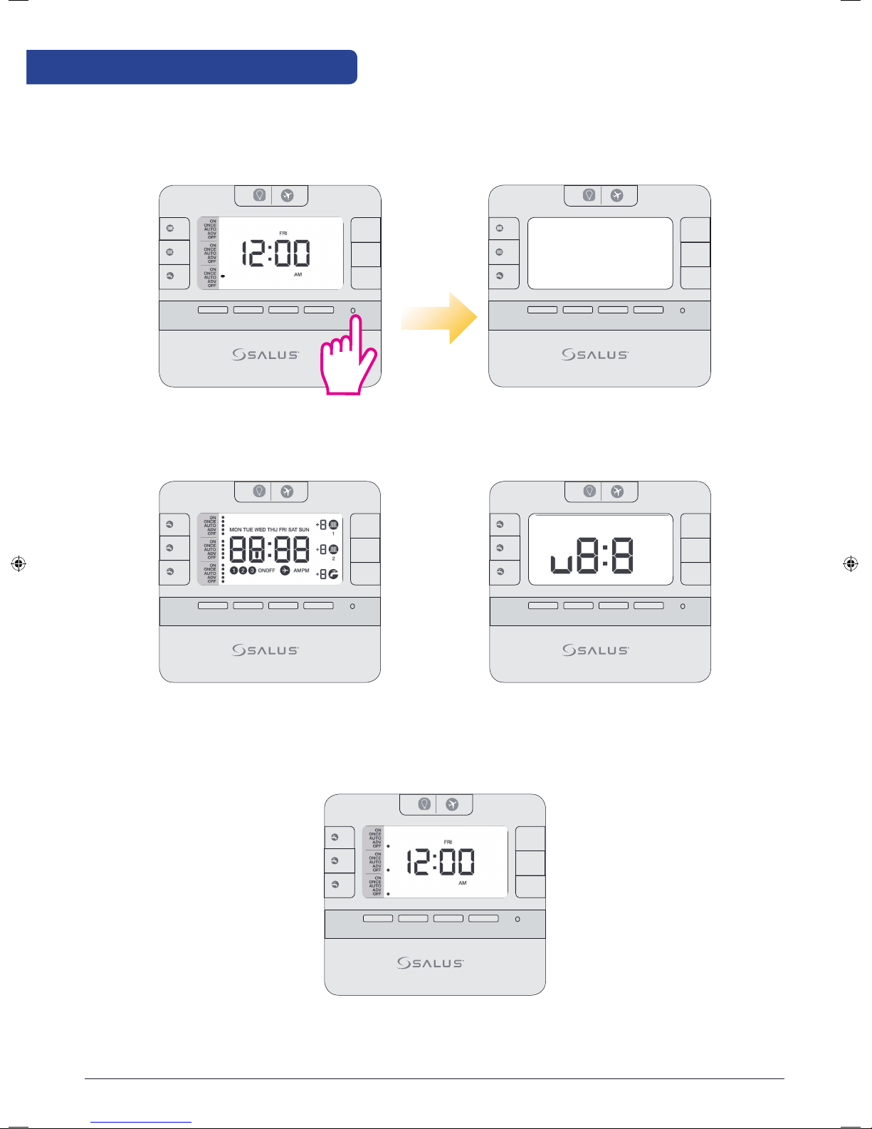
Factory Reset
If you want to return to the factory settings please press the Reset button once (use a pin for this action).
1
1
MODE
2
MODE
MODE
+Hr
+Hr
+Hr
MODE
2
MODE
MODE
+Hr
+Hr
+Hr
<
<
SELECT SET
<
<
Press reset button. LCD will turn OFF.
1
MODE
2
MODE
MODE
<
<
SELECT SET
+Hr
+Hr
+Hr
1
MODE
2
MODE
MODE
<
<
All icons will be displayed. Software version.
SELECT
SELECT SET
SET
+Hr
+Hr
+Hr
20 EP310 Installation Manual
1
MODE
2
MODE
MODE
<
<
SELECT SET
+Hr
+Hr
+Hr
Normal Mode.
Page 21
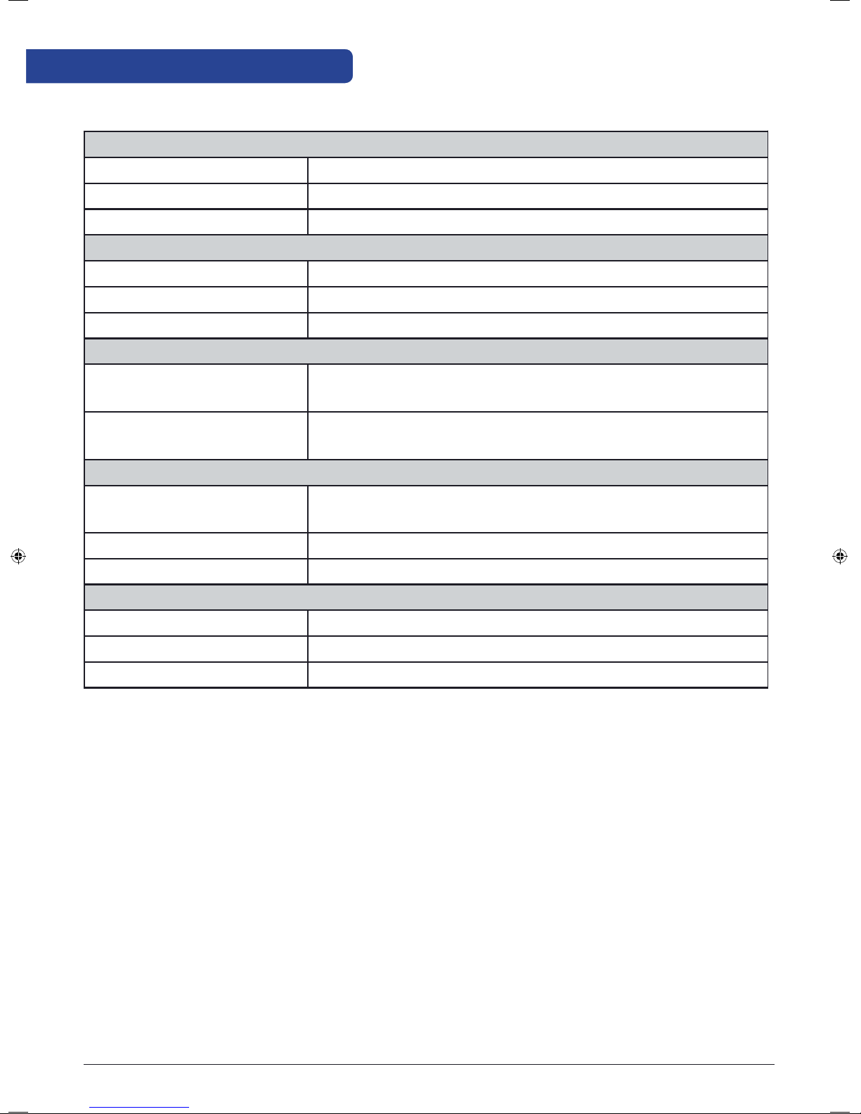
Technical Info
Product Specication
Model: EP310
Type: Surface Mounted Wired Three Channel Programmable Timer
Memory Backup Lithium battery (CR2032 x1pc)
Power control
Rating 230V/50Hz/3(1)A
Relay SPDT
Protection Rating: IP 30
Environment
Operating Temperature/
0°C ~ 50°C, 10% – 90% non-condensing
Humidity:
Storage Temperature/
-20°C~- 60°C, 10% – 90% non-condensing
Humidity
Programs
Program 5-2 or 24hr individual program (selectable by jumper),
3 settings/day, with holiday override.
Boost Override Yes, max 9 hours(selectable by software)
Holiday Override Yes, max 31 days (selectable by software)
Clock
Clock Format 12 or 24 hour (selectable by software)
Clock Accuracy +/-1 min/month
Daylight Saving Time (DST) Yes, Clock automatically adjusted if DST is enabled.
EP310 Installation Manual 21
Page 22

Warranty
SALUS Controls warrants that this product will be free from any defect in materials or workmanship, and shall
perform in accordance with its specification, for a period of two years from the date of installation. SALUS
Controls sole liability for breach of this warranty will be (at its option) to repair or replace the defective product.
Customer Name: ..................................................................................................................................................................
Customer Address: .............................................................................................................................................................
................................................................................................................ Post Code: ...............................................................
Tel No: ................................................................... Email: ......................................................................................................
Company Name: ...................................................................................................................................................................
Tel No: .................................................................. Email: ........................................................................................................
Installation Date: ...................................................................................................................................................................
Installer Name: .......................................................................................................................................................................
Installer Signature: ...............................................................................................................................................................
22 EP310 Installation Manual
Page 23

SALUS Controls PLC
SALUS House
Dodworth Business Park South,
Whinby Road, Dodworth,
Barnsley S75 3SP, UK.
Technical: T: +44 (0) 1226 323961
E: [email protected]
www.salus-controls.com
SALUS Controls is a member of the Computime Group
Maintaining a policy of continuous product development, SALUS Controls plc reserves the right to
change specification, design and materials of products listed in this brochure without prior notice.
Issue Date: April 2017, V001
 Loading...