


TM
9049 Tyler Blvd. • Mentor, Ohio 44060
Phone (440) 974-8888 • Fax (440) 974-0165
Toll-Free Fax 800-841-8003 • buyersproducts.com
Assembly Instructions
WB100B
Heavy-Duty Carbon Steel
Walk Behind Salt Spreader
WB200B
Heavy-Duty Stainless Steel
Walk Behind Salt Spreader
13
TM
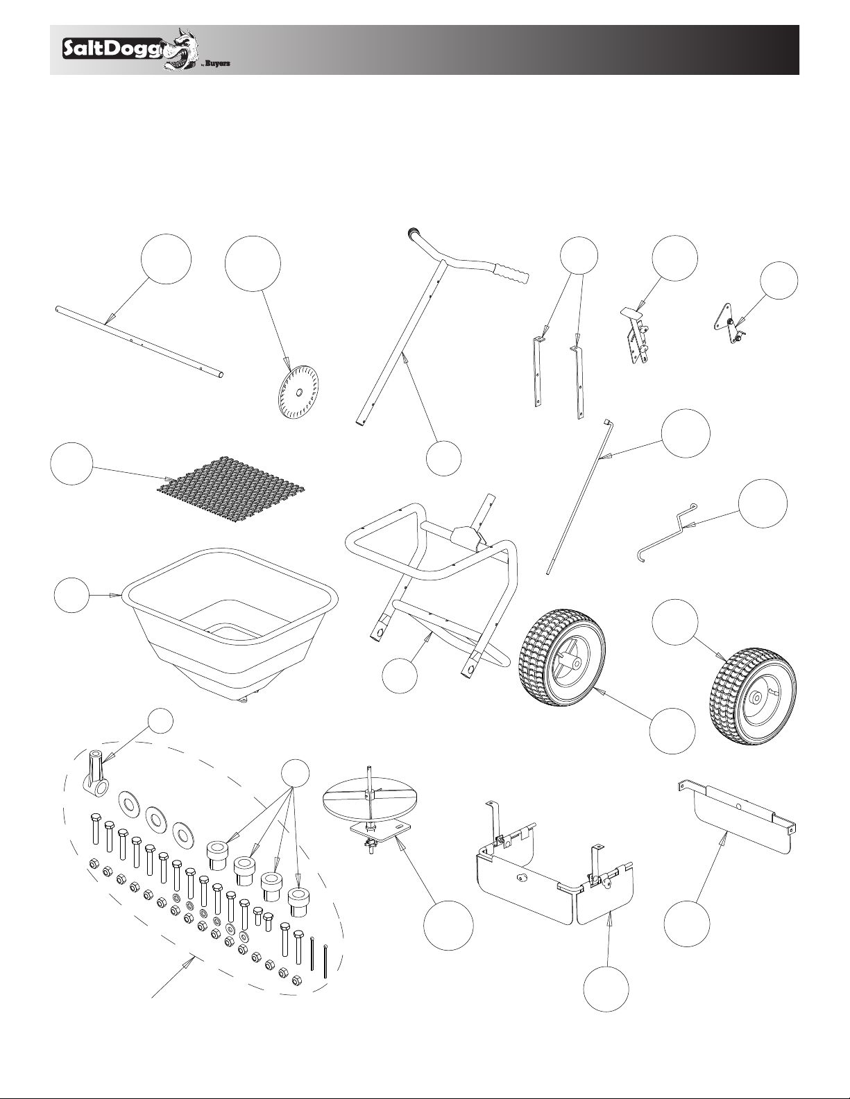
1. Check contents of box against the parts list to make
16
15
8
7
4
12
9
10
11
13
14
2
3
1
6
5
18
17
HARDWARE BAG
sure all components are included. When ordering
replacement or spare parts refer to the parts list for part
numbers.
2
TM
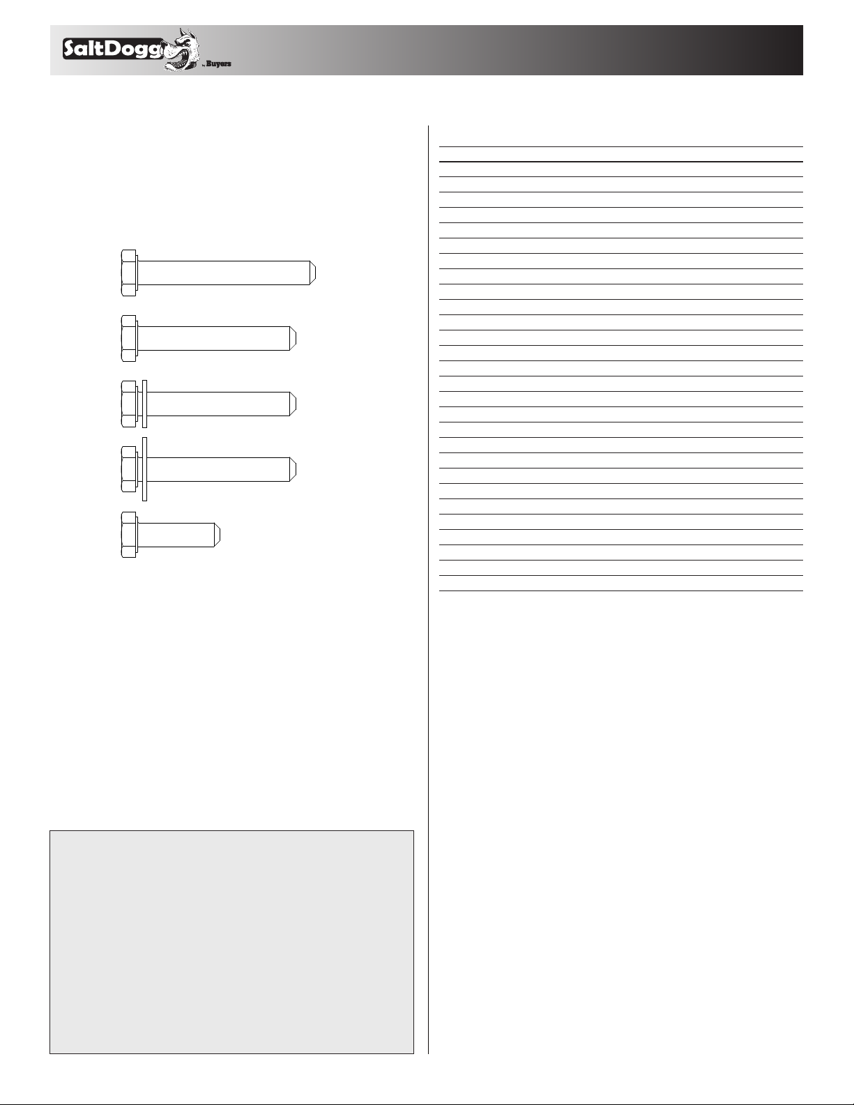
TOOLS NEEDED FOR ASSEMBLY
M6x40 (6)
M6x20 (2)
M6x45 (2)
M6x40 (2)
w/ large
washer
M6x40 (4)
w/ small
washer
• (2) 10mm Wrenches
• (2) ½" Wrenches
• (1) Pliers
Fastener Selection Guide
Parts List (for all figures)
ITEM WB100B WB200 B DESCR IPTI ON
1 3010868 3011729 Frame
2 3010874 3011730 Handle
3 3009156 3009156 Hopper Assembly
– 3009144 3009144 Hopper
– 3009162 3009162 Restrictor Plate Assembly
4 3009157 3011731 Spinner Assembly
– 3009150 3011732 Spinner Shaft
– 3007863 3007863 Spinner
– 3009157* 3011731* Support Bracket
– 3009157* 3011731* Bushing
– 3009157* 3011731* Spacer
– 3008879 3008879 Pinion Gear
5 3008142 3011733 Deflector Assembly
6 3011734 3011735 Rear Deflector Assembly
7 3009160 3011736 Control Handle Assembly
8 3010878 3011737 Linkage Plate Assembly
9 3010880 3011738 Upper Linkage
10 3010879 3011739 Lower Linkage
11 3008135 3008135 Drive Wheel
12 3007862 3007862 Coast Wheel
13 3010870 3011740 Axle
14 3008880 3008880 Drive Gear
15 3010871 3011741 Hopper Support Bracket
16 3008813 3008813 Screen
17 3008881 3008881 Spinner Shaft Support
18 3007865 3007865 Axle Bushings
– 3007993 3007993 Rain Cover
* Must Order Assembly
Manufacturer will repair, or at manufacturer’s discretion will replace
FULL ONE YEAR WARRANTY
any part of this salt spreader which proves to be defective in workmanship or material under normal use for a period of one year from
the date of delivery to the original purchaser. Any cost incurred
in returning the product to the supplier is the responsibility of the
consumer.
EXCLUSIONS
Manufacturer shall not be liable for special, incidental, or consequential damages, or for damages resulting from lack of necessary maintenance, from misuse, abuse, acts of God, or alteration of the product.
Some states do not allow the exclusion or limitation of incidental or
consequential damages, so the above limitation or exclusion may not
apply to you.
3
TM
4
18
13
14
M6x45
17
18
1
DRIVE GEAR
MOUNTING HOLE
DRIVE WHEEL
MOUNTING HOLE
COTTER
PIN
SHIM
WASHERS
COTTER PIN
MOUNTING HOLE
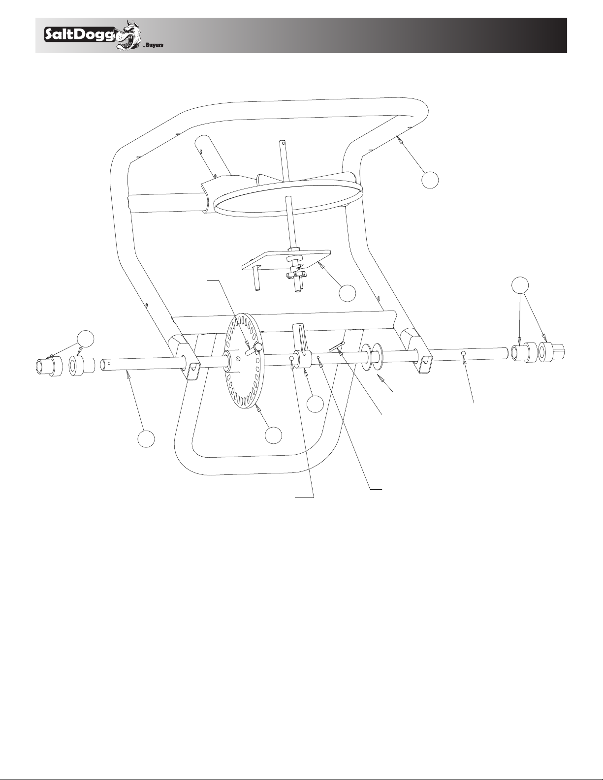
2. Loosely assemble the axle components to the
Fra me(1).
A. Position the Spinner Shaft Support(17) and orient it
as shown.
B. Add two Shim Washers as shown.
C. Add four plastic axle Bushings (18).
3. Position the Spinner Assembly(4) into the Spinner
Shaft Support(17) and assemble the parts so that the
small gear fits into the Drive Gear(14). Using a Cotter
Pin, secure the Shim Washer against the Spinner Shaft
Support as shown.
4. Loosely mount the spinner shaft mounting plate to
the Frame using the two m6x40 bolts that have larger,
flat washers pre-mounted.
4

TM
RIB SIDE MUST
FACE AWAY FROM
LARGE GEAR
SHIM WASHERS
COTTER PIN
M6x4 0
(WITH LARGE
WASHERS)
MOUNT
TO HOLES
IN FRAME
11
M6x45
Shim
Washer
Cotter Pin
M6 Nut
12
5. Mount the Drive Wheel(11) to the Axle using a m6x45
DRIVE WHEEL(11) HAS A HOLE THROUGH THE HUB
USED TO MOUNT TO THE AXLE WITH A M6x45 BOLT
bolt. Mount the Coast Wheel(12) using shim washers
and a cotter pin. Tighten the entire axle assembly as
shown.
A. Make sure the Bushings are fully seated against
the Frame
B. The Coast Wheel side should have only a small
gap between the outside Shim Washer and the
Cotter Pin
5

TM
DRIVE WHEEL NOT
SHOWN FOR CLARITY
3
5
15
15
(4X) M6x40
WITH SMALL
WASHERS
(2X) M6x40
SPINNER
SHAFT
6. Use two m6x40 bolts to fasten the lower part of
the Hopper Support Brackets to the Frame. Position
the Spinner Shaft Straight and then using four m6x40
bolts with smaller washers, loosely assemble the
Hopper Assembly(3), the Deflector Assembly(5), and
the Hopper Support Brackets(15) to the Frame. The
Spinner Shaft will go through a hole in the bottom of
the Hopper Assembly.
6

TM
MAKE SURE PINION IS MESHED WITH LARGE DRIVE GEAR AND TIGHTEN BOLTS
DEFLECTOR'S WINGNUTS SHOULD BE OUTSIDE
OF FLAPS(AWAY FROM SPINNER)
DEFLECTOR NUTS
MAY NEED TIGHTENED
7. Fully tighten the Hopper Assembly to the Frame.
8. Check that the Axle rotates freely, the gears interface
well and tighten the Support Bracket to the Frame.
7

TM
Slide Handle Onto Frame
And Line Up Holes
Deflectors Not Shown for Clarity
Insert Lower Linkage
Into Restrictor Plate
Attach Control
Plate Assembly To Frame
Using M6x40 Bolts
2
8
10
Insert Other End of
Lower Linkage Into
Control Plate Assembly
Secure Bolts & Nuts Snug
Against Washers. Controls
Must Still Be Able to Pivot.
9. Slide the Handle(2) onto the Frame & line up the holes.
10. Insert the Lower Linkage(10) into the Restrictor
Plate pre-attached to the bottom of the Hopper
11. Insert the other end of the Lower Linkage into the
Linkage Plate Assembly(8) as shown.
12. Attach the Linkage Plate Assembly to the Frame
using m6x40 bolts. Secure pivot bolts so nuts are snug
(but not tight) against washers. Controls must be able
to pivot freely.
8

TM
Attach Control Handle
Assembly to Frame Using
M6x40 Bolts
Thread First Jam Nut onto Upper
Linkage and Insert Linkage into
Control Plate Assembly
Secure Linkage with Second Jam Nut and Tighten
Remove Control Handle
from Assembly, Insert
Upper Linkage into
Control Handle, Reattach
Control Handle
Set the Restrictor Plate Fully Open and the
Control Handle to "30" (as shown)
9
9
7
First Jam Nut
13. Attach the Control Handle Assembly(7) to the
Frame using m6x40 bolts.
14. Insert Upper Linkage(9) into the Control Handle.
15. Set the controls by first adjusting the Restrictor
Plate so it is fully open. Next remove the Second Jam
Nut from the Upper Linkage and insert the Upper
Linkage into the small bracket of the Linkage Plate
Assembly. Next set the Control Handle to “30” and
adjust the First Jam Nut so it is flush against the small
bracket. Now reattach the Second Jam Nut and tighten
with two 1/2" wrenches.
9

TM
M6x20 BOLTS
6
16. Using two m6x20 bolts, attach the Rear Deflector
Assembly(6) to the Hopper Support Brackets(as shown)
10

TM
17. Double check that all hardware is tight and the
16
drive system turns properly (it should feel a bit snug).
18. Place the screen(16) inside the hopper.
Operation
1. Before filling Hopper, ensure that the Restrictor Plate
is fully closed and the Screen is in place.
2. Move and tighten the stop bolt to the desired setting.
3. Add material and place rain cover over hopper if
desired.
4. Begin moving forward with the spreader.
5. Pull the Control Handle back to the stop bolt to open
Restrictor Plate and allow material to flow.
6. Before stopping, push the Control Handle fully forward to stop flow.
Maintenance
1. The Hopper and Spinner should be completely emptied and cleaned before storage.
2. The Spreader should be washed and dried before
storage.
3. Check that the Restrictor Plate and Linkage move
freely. Clear out any debris between the Restrictor Plate
and the Hopper.
4. Check that there is no debris in the Gears and that
they move freely.
5. Check torque of all fasteners on a monthly basis.
Operation Notes:
1. The spreader is designed to be operated at a brisk
walking pace. Walking slower or faster will alter the
distribution pattern and amount of the material, as will
the moisture content of the material and other environmental factors.
2. Grease may be applied to the Pinion and Large Drive
Gear as desired.
CAUTION
When filling hopper, make certain there are no
large objects within the material. Objects larger
than the openings in the Screen may cause the
spreader to clog or even damage the drive system.
Never leave material in the hopper when not in use.
11

TM
9049 Tyler Blvd. • Mentor, Ohio 44060
Phone (440) 974-8888 • Fax (440) 974-0165
Toll-Free Fax 800-841-8003 • buyersproducts.com
12
3011655 Rev B
 Loading...