

TM
Phone (440) 974-8888 • Fax (440) 974-0165
Toll-Free Fax 800-841-8003 • saltdogg.com
Installation Instructions
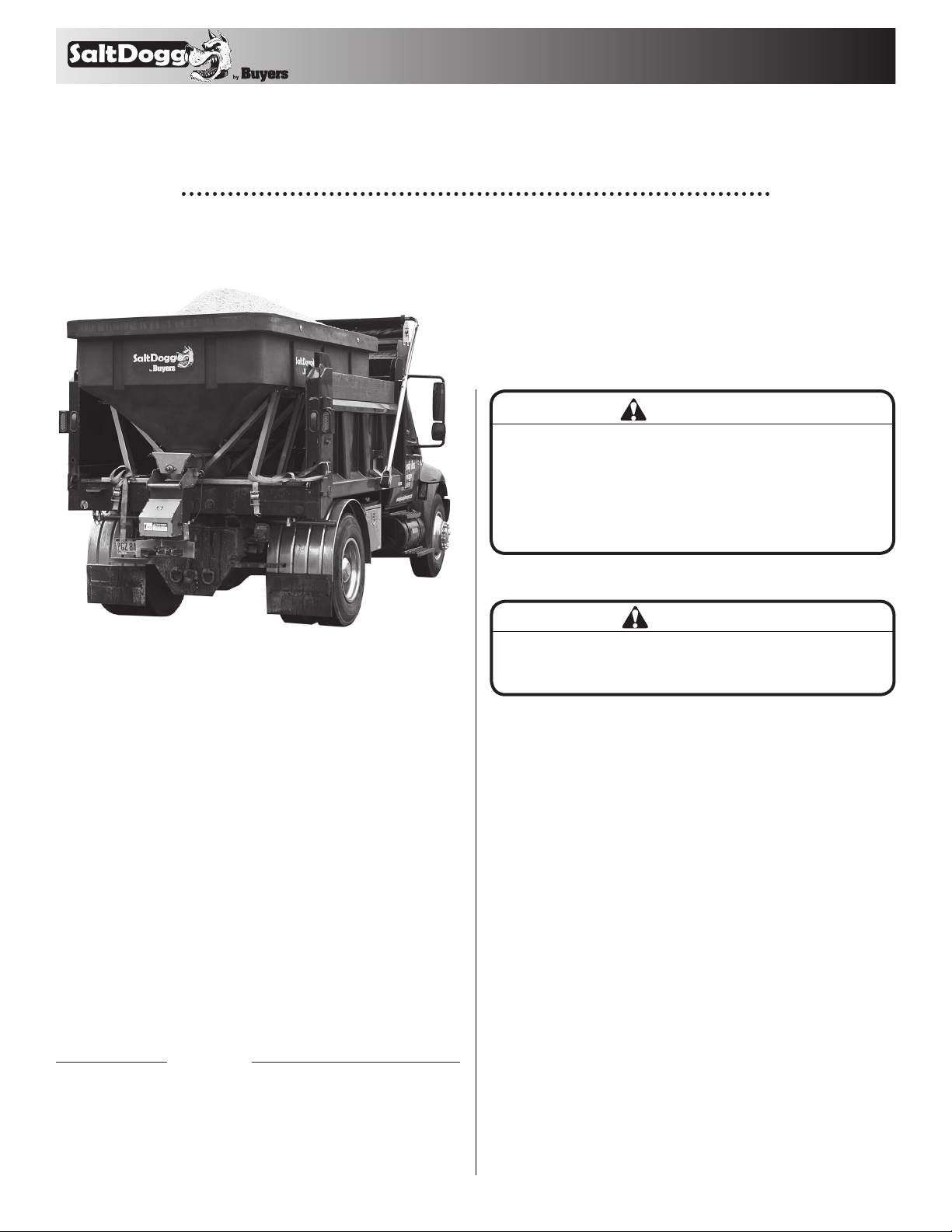
SaltDogg® Electric Drive Poly Hopper Spreader
6.0 cubic yards
Improper installation and operation could cause
personal injury, and/or property damage. Observe
the following Safety Precautions before, during and
after operating this spreader. By following these
precautions and common sense, possible injury to
persons and potential damage to this machine may
be avoided.
9049 Tyler Blvd. • Mentor, Ohio 44060
WARNING
Table of Contents
General Information ........................................1
Safety Precautions ........................................... 1
Installation Instructions ............................. 2-4
Spreader Operation ...................................... 3-4
Spreader Maintenance .................................... 4
Repair Parts & Drawings ............................ 5-8
Warranty Information ...................................... 8
General Information
Overall Length: 133.5 inches
Overall Width: 77 inches
Overall Height: 57 inches
Empty Weight: 1,344 lbs
Capacity Struck: 6.0 cu. yd.
Vehicle Requirements
Trucks with minimum GVWR 25,999 lbs.
150 AMP or higher alternator is recommended.
Average Material Weights
Materials to use Weight (pounds per cubic yard)
Fine Salt-Dry 2,250
Coarse Salt-Dry 1,431
Sand Coarse-Dry 2,565
Note: To calculate the total spreader weight (including ice
control material), add the empty spreader weight plus the ice
control material and spreader accessories.
CAUTION
Do not overload vehicle beyond the vehicle’s GVWR
or GAWR. Check vehicle’s load rating certification
sticker for maximum vehicle capacity.
Safety Precautions
1. Read this entire Owners Manual before operating this
spreader.
2. Read all safety decals on the spreader before operating.
3. Check to make sure all safety guards are securely
mounted into place before operating this spreader.
4. Verify that all personnel are clear of the spreader spray
area before starting or operating this spreader.
5. Do not over-load your vehicle beyond payload limits. If
there are any questions, contact the vehicle manufacturer.
6. Do not adjust, clean, lubricate or unclog material jambs
without first turning off the spreader.
7. Do not climb on or in the spreader during operation. Do not
ride on the spreader while the vehicle is in motion.
8. Make sure the spreader is securely fastened to the vehicle
in accordance with this manual.
9. Do not operate a spreader that is in need of maintenance
or repairs.
10. Batteries normally produce explosive gases which can
cause personal injury. Always disconnect the battery before
removing or replacing electrical components.
11. Do not leave unused material in hopper. Material can
freeze or solidify, causing spreader to not work properly, and/
or damage the unit. Empty and clean after each use.
—continued inside
1
TM
Installation Instructions
1. MOUNTING THE SPREADER ONTO THE VEHICLE:
A. Remove the tailgate from the vehicle (if equipped) as well
as any other object which will interfere with the spreader.
B. Check truck’s bed for all kinds of sharp debris or foreign
objects. They can cut and seriously damage poly hopper.
C. Remove chute, hardware kit from inside spreader. If
spreader has been used make sure there is no material left in
the hopper.
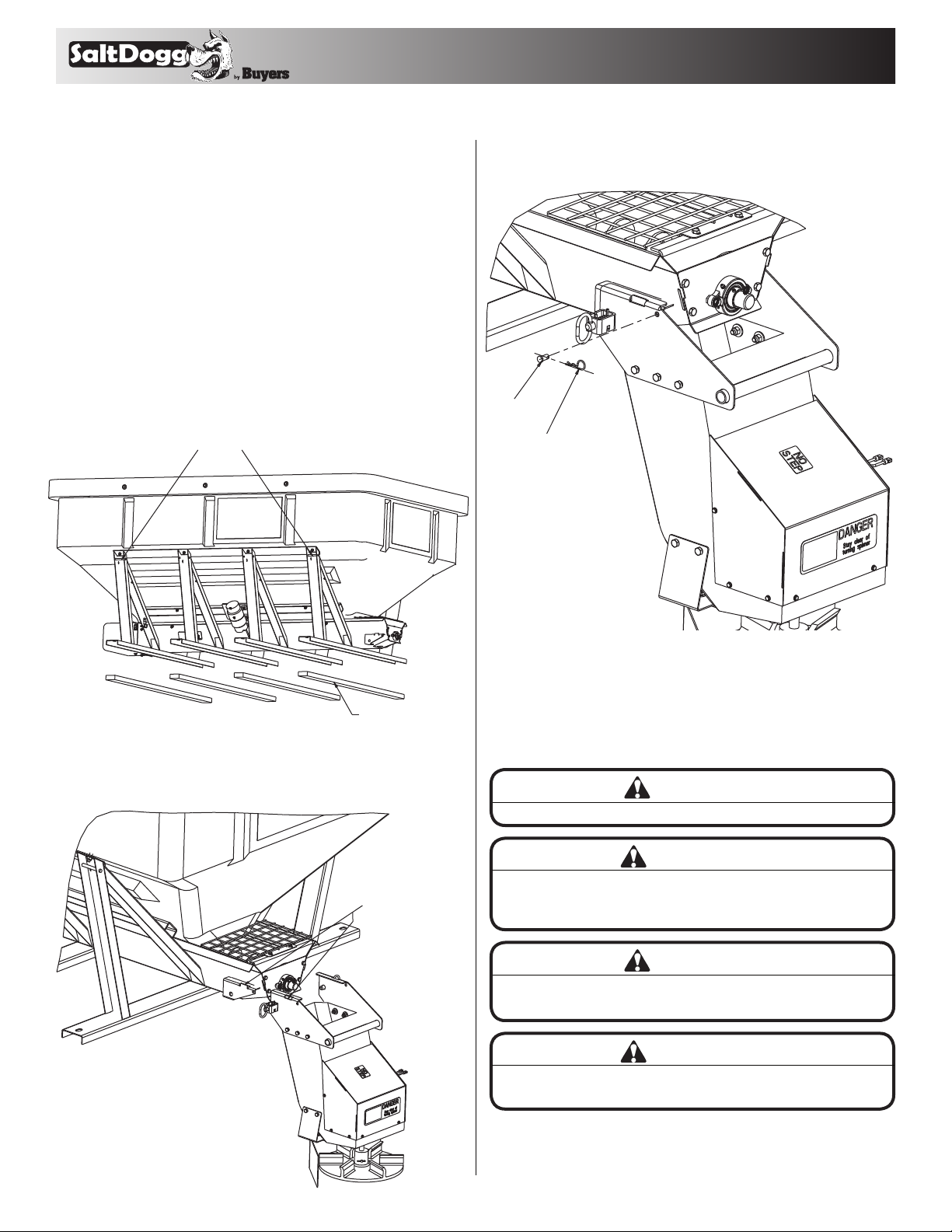
D. Prepare 4 boards as shown in Fig. 1. A board size is
2" x 4" x 70" long minimum (cross boards from shipping pallet
can be used). Boards can be as long as width of inside of
trucks body.
E. Next, set the spreader in the truck body. Use four bars on
the frame to lift the spreader (Fig. 1).
Fig. 1
Lift Spreader By These Bars
G. Secure chute in position using spring latches and clevis
and hair pins as shown in Fig. 3.
Fig. 3
3001238
CLEVIS PIN
3001257
HAIR PIN
Boards 2" x 4" x 70"
F. Lower spreader onto 2" x 4" boards positioned in truck bed.
Attach chute to the spreader as shown in Fig.2
Fig. 2
Slide and Lower Chute
On Chute Brackets.
Bracket Tabs Must
Go Thru Openings
In Chute Hangers.
H. If necessary, slide spreader rearward to have at least 2"
clearance between chute and rear most vertical obstruction.
I. Make sure the spreader is centered from side to side and
rearmost board rests fully on trucks body.
J. Using holes in cross members fasten spreader to the
vehicles body.
CAUTION
Never lift spreader with material in the hopper.
WARNING
Do not drill holes into fuel tanks, fuel lines, thru
electrical wiring, etc that may be damaged by
drilling.
CAUTION
Inspect straps and hardware after each time spreader
is loaded. Tighten straps and hardware if necessary.
WARNING
Important! Do not use ratchet straps or tailgate latch
exclusively! Always fasten spreader to the vehicle!
K. In addition, secure spreader using four ratchet straps
attached to tie down bars on hopper frame or chain tie down
kit (sold separately). Always tighten straps evenly!
2
TM
2. CONTROL BOX AND VEHICLE WIRING HARNESS
INSTALLATION
Make sure you have connected the proper wire color.
THIS IS WIRE GROUND ELECTRICAL SYSTEM! NO
CONNECTIONS TO TRUCK’S FRAME OR BODY ALLOWED!
NOTE: Always disconnect battery before attempting to
install electrical components on your vehicle.
A. Mount the controller in a convenient location in the truck
cab. It is recommended not to mount the controller directly in
front of heat vents. Allow ample air space around controller.
B. Route both wire harnesses into truck cab through firewall
(it maybe necessary to drill holes). Insulate hole to avoid
water leaks.
C. Insure no wires are nicked or damaged during installation.
D. Connect the 4-pin connector on the wire harness to the
control box 4-pin connector.
WARNING
Do not drill holes into fuel tanks, fuel lines, through
electrical wiring, etc that may be damaged by drilling.
To insure good performance of your spreader, check
the condition of truck’s electrical system. Using digital
voltmeter, check alternator and battery voltage. With
engine running and head lights and heater fan ON
good voltage reading should fall between 13.0 and
15.3 volts. If voltage reading falls out of this range,
check and adjust your electric system.
CAUTION
Do not mount controller in the way of air bag
deployment!
IMPORTANT! Make sure all wires securely attached to
vehicle or spreader. Use wire ties and/or wire clamps to
attach wires. All excess wires must be rolled into bungles
and attached to vehicle or spreader.
E. Connect the 2-pin connector on the power cable to the
control box mating connector.
F. Connect wire harness single connectors to control box
connectors.
G. Connect fuse connector to the fuse terminal or ignition
switch (5 AMP max).
H. Lay out a path for the power cable to the battery, use
quick ties to secure power cable.
DO NOT CONNECT TO BATTERY AT THIS TIME!
I. Lay out path for wire harness to the rear of the vehicle. It
is recommended to stay clear of the exhaust system. Excess
heat can damage the wire harnesses. Use quick ties to
secure harness to underbody.
J. Connect the wire harness to the motors and vibrator. Make
sure wire colors on wire harness match colors on the motor.
Thoroughly clean battery terminals. Make sure battery
terminals have no tarnish or corrosion.
DO NOT CONNECT WIRE HARNESS TO DAMAGED
OR CORRODED TERMINALS! IT MAY RESULT IN
OVERHEATING, LOST POWER AND POTENTIAL
CONTROLLER DAMAGE!
K. Connect the power cable directly to the battery.
L. Insure all functions of the controller are working properly.
M. Observe auger moving in proper direction. If direction is
wrong reverse wires between Motor and Wire Harness.
N. Optional spot light (5 AMP max) can be installed on
spreader. Remove cap from single white wire. Connect light
to this wire and trucks frame.
Controller Connection (fig. 4)
A. SHPE6000 is equipped with a dual independent speed
controller. To start spreader, press "POWER" switch. Switch
will be illuminated. Auger and spinner will start rotating full
speed for 2-3 sec then will slow down to originally dialed
speeds. Auger and spinner can be adjusted independently.
Different materials and different moisture contents will
affect spreader performance. In some cases material
alternatives may be necessary.
B. To activate vibrator press "VIBRATOR" switch, vibrator
switch will illuminate.
C. To stop spreader press "ON-OFF" switch again.
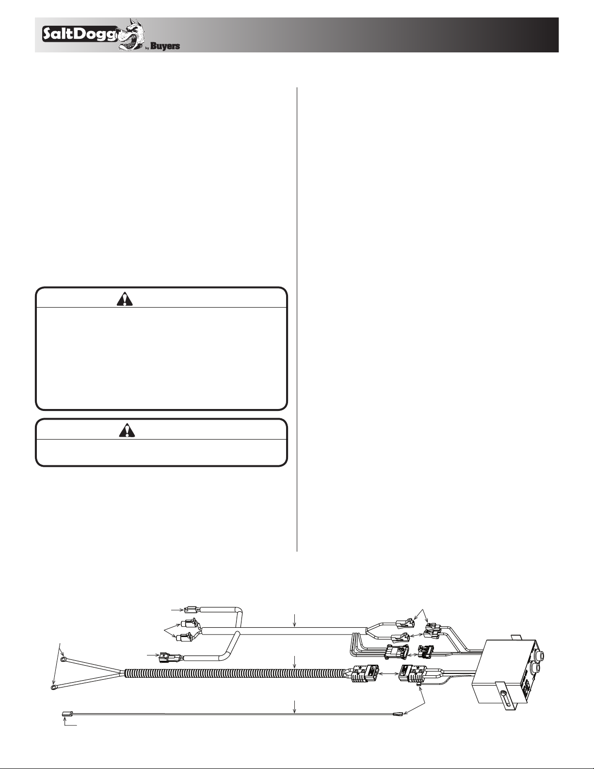
Fig. 4
Connect to Battery
Terminals Only
Connect to Fuse or Wire in Fuse Panel
Controlled By Ignition Switch - 5 Amp Max.
Connect to
Chain/Auger
Gear Motor
Connect to
Chute Motor
Connect to
Vibrator
3016944
3016943
0203700
3
Connect
3016934
Controller
Connect
Connect
Connect
Connect

TM
D. SHPE6000 controller is equipped with electronic overload
and current spikes protection. Controller is not serviceable.
Controller has "Jam" light. If auger becomes jammed by
chunk of material or foreign debris "Jam" light will be
illuminated and controller will turn it self "OFF".
Controller can be restarted normally after jam removal.
Controller is equipped with internal vibrator circuit breaker.
Vibrator circuit breaker will trip and vibrator switch light
will turn "OFF" if vibrator becomes overloaded. To reset
vibrator circuit breaker turn vibrator switch off for 30 sec
then turn it on again.
Vibrator can operate continuously for 30 min max with 15
min brakes to avoid overheating.
E. Spreading pattern can be controlled by repositioning of
spinner shield on the shield bracket. Loose two screws and
slide shield into desired position, then tighten screws.
Maintenance Instructions
A. Wash spreader after every use. Make sure no material left
under auger and/or inside trough.
B. Inspect and retighten fasteners after every 10-15 hours of
operation.
C. Lubricate bearing every using general automotive grease
according to Fig.5
D. Inspect terminals/ connectors every time you disconnect
spreader from wire harness. Apply thin layer of dielectric
grease on terminals. If any tarnish/corrosion found, clean
terminals and apply dielectric grease.
End of Season Maintenance.
A. Wash spreader. Make sure no material or residue left in
and outside hopper.
B. Lubricate bearing using general automotive grease.
C. Inspect wire harness, connectors for broken insulation,
missing components. Replace if necessary.
D. Apply dielectric grease on all electrical connectors.
E. Store hopper indoors, in dry, cool place.
F. Inspect, clean and repaint frame.
G. Remove controller from truck. Store controller indoors, in
dry, cool place
WARNING
Never attempt to lift spreader with material in hopper!
WARNING
Never leave material in hopper for extended period
of time. Material can freeze, solidify and seriously
damage the spreader.
Remove Cover
Grease Bearing Ever y 15-20 Hours
Fig. 5
Grease Every 10 Hours
4

TM
Chute Assembly
9
12
16
1
2
18
10
11
15
13
Bill of Materials
ITEM NO. PART NO. QT Y. DESCRIPTION
3012374
10
11
1
2
3
4
5
6
7
8
9
30140 78
3012802
-
3012393
30 0 7113
3012397
-
-
1 Chute, SHPE4000
1 Motor 12VDC, .5 HP Spinner
1 Retainer, Motor, Chute
4 Screw, HEX HD CAP 5/16-18 x 1.0 SST
4 Washer, 5/16 SAE SST
1 Spinner, 14" Poly CW
1 Pin, Clevis, 5/16 x 2-1/2, .141 Hole, ZN
1 Cotter Pin, 1/8 x 1, ZN
1 Bracket, Shield Chute
10 Screw, HHC-3/8-16 x 1.25 SST
12 Washer, Flat 3/8 USS SST
14
ITEM NO. PART NO. QT Y. DESCRIPTION
12
13
14
15
16
17
18
19
20
21
-
3012396
3001255
3019255
3012834
3006753
-
3007844
30 02631
10 Nut, Nylock 3/8-16 x 7/16 SST
1 Shield Chute
2 Screw HHC 3/8-16 x 1, 304 SST
2 Nut, Hex Flange 3/8-16 SST
1 Chute Hanger Weldment
1 Cover Weldmentt, Chute
1 Wire Harness, Chute
Screw, Sheet Metal #12x1.0 Hex Washer
8
HD SST
1 Decal, "DANGER STAY CLEAR"
1 Label, "NO STEP"
21
20
17
19
3 4 5 6 7 8
5

Hopper Assembly
18
21
1
4
TM
30
17
31
20
23
25
24
10
9
33
13
12
22
19
29
32
27
26
28
3
14
15
16
2
5 678
6
11

TM
Hopper Assembly Bill of Materials
ITEM NO. PART NO. QT Y. DESCRIPTION
3018430
10
11
12
13
14
15
16
17
1
2
3
4
5
6
7
8
9
3018655
-
-
3018639
30148 5 8
3013 821
141020 0
300125 0
-
-
301916 6
30173 56
3007066
3018855
1 Hopper, Poly 6 cu.yd.
1 Trough Weldment SHPE6000
32 Washer, Flat .5 ID 1.5 OD SST
20 Screw, HHC 1/2-13x1.5 SST
27 Nut, Nylock 1/2-13 SS
1 Auger SHPE 6.0 x 4.0 RH
1 Sleeve Auger Adapter
1 Gear Motor Conveyor 12 VDC
1 Bearing, Flanged 1-1/8"
10 Nut, Nylock 3/8-16 x 7/16 SST
1 Screw, HHC 1/2-13 x 3 SST
4 Washer, Flat 3/8 USS SST
4 Screw, HHC 3/8-16 x 1 304 SST
1 Vibrator 900 lbs. 12 VDC
6 Washer, External Tooth Lock 3/8 SS
4 Screw, HHC 3/8-16 x 2 SST
2 Screen Bracket Weldment
ITEM NO. PART NO. QT Y. DESCRIPTION
3019795
18
19
20
21
22
23
24
25
26
27
28
29
30
31
32
33
3019163
301916 4
3017121
3019236
-
3019243
3019791
9240086
3018857
66070
3019878
1 Screen Support Weldment
2 Hanger, Inverted V
16 Screw, HHC 3/8-16 x 3/4 SST
1 Deflector, Inverted V
2 Bracket, Receptacle SZ8 Deutsch
1 Cover G Motor, Auger
4 Washer, 5/16 SAE SST
4 Screw, Hex HD CAP 5/16-18 x 1 SST
1 Bracket Bearing, Weldment
1 Auger Cover Weldment
1 Bearing, 1-1/4 Flange 2 Hole
6 Screw, Hex Head CAP 1/2-13 x 5 SST
2 Screen Mesh Half
6 Snapper Pin, 1/4 x 3.5, Yellow ZN
2 Screw, Hex HD, 5/16-18 x 3/ Gr. 5 SS
1 Extension Wire Harness 8ft. Motor
7

SHPE6000 Assembly
6
9049 Tyler Blvd. • Mentor, Ohio 44060
TM
Phone (440) 974-8888 • Fax (440) 974-0165
Toll-Free Fax 800-841-8003 • saltdogg.com
4
5
8
9
2
Bill of Materials
ITEM NO. PART NO. QT Y. DESCRIPTION
3018639
1
2
3
4
5
6
7
8
9
3019256
3021674
3016934
3016943
3016944
020370 0
300123 8
3001257
1 Hopper Assembly, SHPE6000
1 Chute Assembly, SHPE6000
1 Hardware Kit, SHPE6000
1 Controller, Speed, 12 VDC, 60 AMP
1 Power Cord
1 Wire Harness Main
1 Wire Assembly, 36" Long
2 Pin, Clevis 3/8 x 3/4 w/ 1/8 Hole
2 Pin, Hair Cotter SS
7
1
SHPE6000 SALTDOGG® SPREADER
3
This warranty replaces all previous warranties and no employee of this
company is authorized to extend additional warranties, or agreements,
or implications not explicitly covered herein.
Buyers Products Company warrants all parts of the product to be free
from defects in material and workmanship for a period of one (1) year.
Parts must be properly installed and used under normal conditions.
Normal wear is excluded.
Any part, which has been altered, including modifications, misuse,
accident, or lack of maintenance will not be considered under this
warranty.
The sole responsibility of Buyers Products Company under this warranty
is limited to repairing or replacing any part(s), which are returned,
prepaid, 30 days after such defect is discovered, and returned part(s) are
found to be defective by Buyers Products Company.
Authorization from Buyers Products Company must be obtained before
returning any part. The following information must accompany defective
parts returned to Buyers Products Company: R MA #, spreader model,
serial number, date installed, and distributor from whom purchased.
Buyers Products Company shall not be liable for damage arising out
of failure of any unit to operate properly, or failure, or delay in work, or
for any consequential damages. No charges for transportation or labor
performed on any part will be allowed under this warranty.
WARRANTY INFORMATION
8
3021675 Rev. A
 Loading...