

SaltDogg SHPE0750, SHPE1500, SHPE2000, SHPE4000 User Manual
TM
Installation Instructions
3014199 SHPE Spreader Controller
Serial Number 15000 and higher.
IMPORTANT!
Before installation, check your truck's battery and alternator
using load tester. Do not proceed to installation if truck electrical system does not function properly.
NOTE: Always disconnect battery before attempting to install
electrical components on your vehicle.
1. Mount the controller in a convenient location in the truck
cab. It is not recommended to mount the controller directly in
front of heat vents. Allow ample air space around controller.
CAUTION!
Do not mount controller in the way of air bag deployment!
2. Route both wire harnesses into truck cab through firewall
(it maybe necessary to drill holes). Insulate hole to avoid
water leaks. Insure no wires are nicked or damaged during
installation.
3
9049 Tyler Blvd. • Mentor, Ohio 44060
Phone (440) 974-8888 • Fax (440) 974-0165
Toll-Free Fax 800-841-8003 • saltdogg.com
3. Connect the round connecter on the wire harness to the
control box.
4. Connect the 2-pin rectangular connector on the power
cable to the control box.
5. Lay out a path for the power cable to the battery, use
quick ties to secure power cable.
DO NOT CONNECT TO BATTERY AT THIS TIME!
6. Lay out path for wire harness to the rear of the vehicle.
Stay clear of the exhaust system. Excess heat can damage
the wire harnesses. Use quick ties to secure harness to
underbody.
7. Connect the wire harness to the motors and vibrator.
8. Connect red wire to battery positive terminal. Connect
black wire to battery negative terminal.
THIS IS A WIRE GROUND ELECTRICAL SYSTEM! NO
CONNECTIONS TO TRUCK’S FRAME OR BODY ALLOWED!
In trucks with dual battery systems always connect power
cable to primary battery (larger capacity/ truck starting
battery).
Controller Operation
4
GEAR MOTOR MAY
HAVE INTEGRATED
HARNESS
5
INPUT WIRES
RED WIRE (10AWG) - BATTERY “+”
BLACK WIRE (10AWG) - BATTERY “-”
RED WIRE (16 AWG) IGNITION “+”
OUTPUT TERMINALS/WIRES:
A - BROWN (20 AMP FUSE) - LIGHT
B - RED - AUGER POSITIVE
C - GREEN - AUGER NEGATIVE
6
7 8
1
D - BLACK - VIBRATOR NEGATIVE
E - GRAY (30 AMP FUSE) - VIBRATOR POSITIVE
F - YELLOW - SPINNER POSITIVE
G - BLUE - SPINNER NEGATIVE
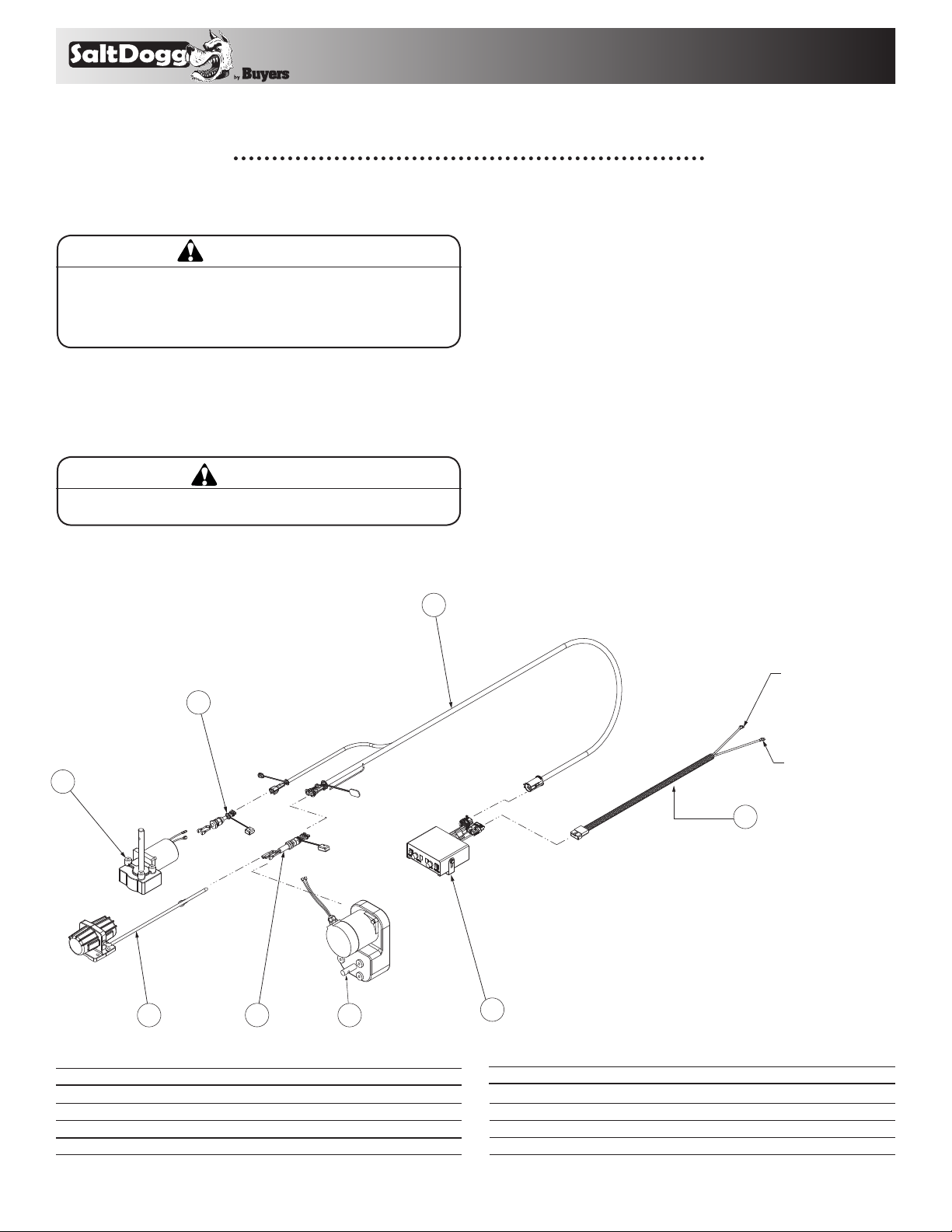
Parts List
ITEM PART NO. QTY DESC RIPT ION
1 3014199 1 CONTROLLER, SHPE, SALTDOGG
2 3006842 1 POWER CABLE, CONTROL BOX
3 3006724 1 WIRE HARNESS, MAIN
4 3006753 1 WIRE HARNESS, CHUTE
Buyers Products Company assumes no responsibility for installations not made in accordance with these instructions.
ITEM PART NO. QTY DESC RIPT ION
5 3006833 1 GEAR MOTOR 12 VDC. SPINNER
6 3006844 1 WIRE HARNESS
7 3009995 1 GEAR MOTOR, AUGER SHPE
8 3007416 1 VIBRATOR 200 LBS 12 VDC
2
BLACK WIREBATTERY NEGATIVE
RED WIREBATTERY POSITIVE
1

9049 Tyler Blvd. • Mentor, Ohio 44060
TM
Phone (440) 974-8888 • Fax (440) 974-0165
Toll-Free Fax 800-841-8003 • saltdogg.com
1. To start spreader, be sure that truck engine is running to prevent battery from discharging. Flip power switch to ON
position. Controller switches will illuminate. Auger and spinner motors will start with full speed for a short time (displays
will show 9) and then drop to the speed settings selected.
2. To adjust speed simply rotate speed knobs until desired speed number is achieved.
3. To activate vibrator flip the Vibrator switch to ON position. Vibrator switch will illuminate. To turn vibrator OFF flip switch
to OFF position.
4. To turn controller OFF, simply flip power switch to OFF position.
5. If battery voltage drops below 10 VDC, controller shuts off automatically.
Controller Codes
AUGER DISPLAY
1 blinking blinking
FF
SPINNER
DISPLAY
Ignition wire connected to 12 VDC source,
positive wire is not connected to battery
Positive motor wire in wire harness shorted
2 F
to trucks body/frame.
Internal fuse 40 AMP blown.
Positive motor wire in wire harness shorted
3 F
to trucks body/frame.
Internal fuse 40 AMP blown.
Short circuit between vibrator wires and
trucks body/frame.
4 U F
Short circuit between vibrator wires.
External 30 AMP fuse is blown.
Internal fuse 40 AMP blown.
5 A Missing connection in Auger circuit. Find and eliminate missing connection.
6 P Missing connection in Spinner circuit. Find and eliminate missing connection.
Speed number is blinking.
7
Auger motor is alternating
Auger jammed, auger motor overloaded.
forward/ reverse rotations.
8
Speed number
is blinking.
Spinner motor overloaded.
9 U Missing connection in vibrator circuit. Find and eliminate missing connection.
10 L Low battery voltage. Check trucks electrical system.
11 C Controller temperature is higher than 160F Relocate controller to have better cooling.
12 H
Auger motor wires in wire harness shorted to
each other. Short location close to controller.
Spinner motor wires in wire harness shorted
13 H
to each other. Short location close to
controller.
Speed number is blinking,
14
motor stopped.
15
Speed number
is blinking,
motor stopped.
Auger motor wires in wire harness shorted to
each other. Short location close to motor.
Spinner motor wires in wire harness shorted
to each other. Short location close to motor.
MOTOR, WIRE HARNESS,
CONTROLLER STATUS
ACTION REQUIRED
Connect positive wire to battery
Find and eliminate short circuit.
Replace fuse.
Find and eliminate short circuit.
Replace fuse.
Find and eliminate short circuit.
Replace vibrator.
Replace fuse.
Clear jam in auger trough.
Adjust hopper baffles to reduce auger load.
Reduce amount of material falling on spinner
disc. Clear spinner disk before starting
spreader.
Find and eliminate short circuit.
Find and eliminate short circuit.
Find and eliminate short circuit.
Find and eliminate short circuit.
WARRANTY
Buyers Products Co. warrants all truck/trailer hardware manufactured or distributed by it, to be free from defects in material and
workmanship for a period of one year from date of shipment. Parts must be properly installed and used under normal conditions.
Any product which has been altered, including modification, misuse, accident or lack of maintenance will not be considered under
warranty. Normal wear is excluded. The sole responsibility of Buyers Products Co. under this warranty is limited to repairing or replacing any part
or parts which are returned, prepaid, and are found to be defective by Buyers Products Co. Authorization from Buyers Products Co. must be obtained
before returning any part. No charges for transportation or labor performed on Buyers’ products will be allowed under this warranty.
2
3019470 Rev. C
 Loading...