

Page 1
TM
Installation & Operator’s Manual
LS4 Liquid Spray System
9049 Tyler Blvd. • Mentor, Ohio 44060
Phone (440) 974-8888 • Fax (440) 974-0165
Toll-Free Fax 800-841-8003 • saltdogg.com
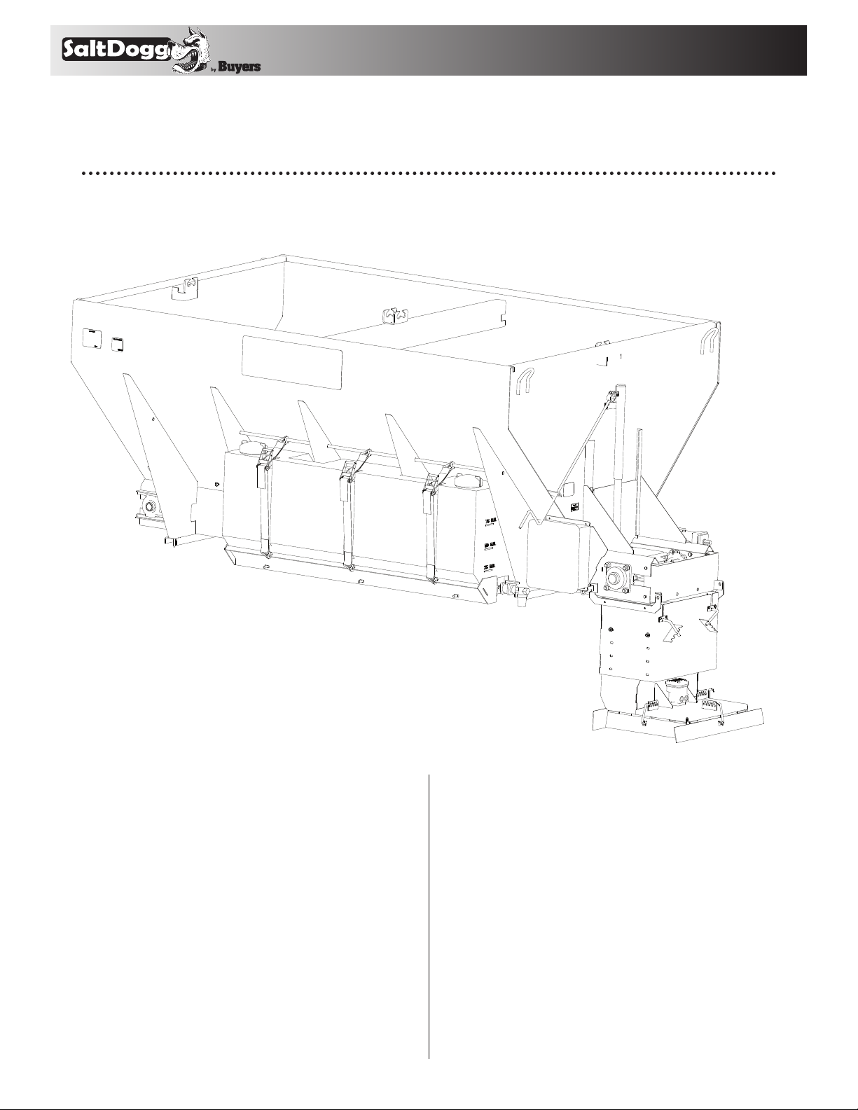
Installation Instructions
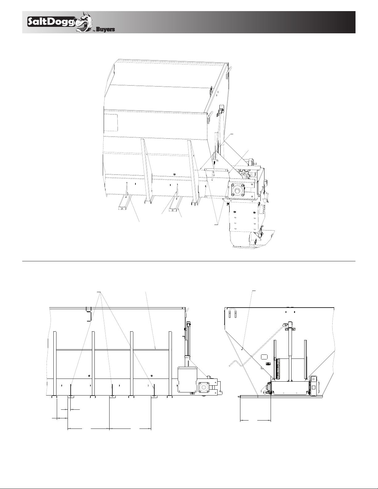
1. Position pump enclosure bracket
(#3028485) 4” from rear gusset on driver side
of hopper spreader, (see figs. 1). Make sure
bracket is rested on hopper’s sill.
2. Weld pump enclosure bracket (#3028485)
in place as it shown in fig.1.
3. Position reservoir brackets (#3010977),
gussets (#3011128) and bracket tie downs
(#3011124) as shown in fig.2. Weld all parts in
place as shown in fig.2 and fig.1.
4. Place reservoir (#3010816) on brackets and
secure it using retainer (#3010979) as shown in
fig.3.
5. Use three (#1496505) (see fig. 3) 1-3/4” x 5”
ratchet tie downs to secure reservoir.
6. Plumb: Reservoir, ball valve, filter, pump
enclosure, and spray nozzles according to
plumbing schematic using supplied fittings,
hose, and hose clamps. Do not use Teflon
tape on threads. Use liquid thread sealant.
(see fig. 5, 6, & 7).
7. Two 11/16” diameter holes are predrilled in
the chute guide (#3010180) for installation of
two liquid spray nozzles, see fig.3. Installation
on different brands of spreaders may require
different nozzle locations.
—continued inside
1
Page 2
9049 Tyler Blvd. • Mentor, Ohio 44060
TM
4" FROM GUSSET
Phone (440) 974-8888 • Fax (440) 974-0165
Toll-Free Fax 800-841-8003 • saltdogg.com
3028485
WELD ALL AROUND
BRACKETS AND GUSSETS
3011128
WELD ALL AROUND
BRACKET, TIE DOWNS
3010977
WELD BOTH SIDES
Fig. 1
WELD ALL AROUND
BRACKET, TIE DOWN
6.75
1.75
26.0
19.0
26.0
Fig. 2
2
Page 3
9049 Tyler Blvd. • Mentor, Ohio 44060
TM
Fig. 3
Phone (440) 974-8888 • Fax (440) 974-0165
Toll-Free Fax 800-841-8003 • saltdogg.com
Fig. 4
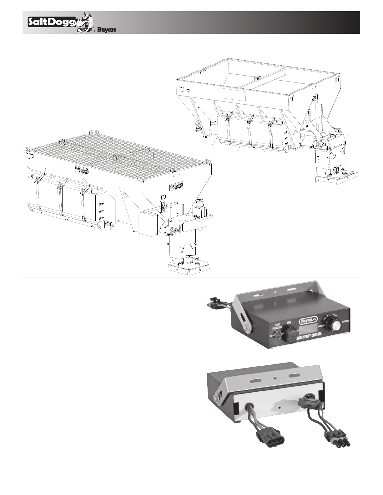
LS4 can be adapted for Buyers'
4 and 4.5 cubic yard spreaders.
Cab Controller Installation
Instructions (Fig. 5)
1. Install cab controller (#WSE1) in cab for convenient
driver operation. Mounting bracket and fasteners
included.
2.
Route 8' wire harness (#WSE24) under dash from
controller (#WSE1) to truck’s fuse panel.
3. Ground “black” wire from controller to truck frame
or truck’s battery (not dash).
4. Attach “green” wire in 8' wire harness (#WSE24) to
a fused and keyed 15 Amp hot wire circuit.
5. Connect main power “white” wire in 8' wire harness (#WSE24) to fuse box that is “hot” full time or to
battery “positive”.
6. Route the 25' wire harness (#WSE25) from the
rear of the spreader to the cab. Plug connector on
controller (#WSE1) to the connector on pump harness
(#WSE25).
3010816
25' Cable Connector
3010979
Fig. 5 WSE1 Cab Controller front view
WSE25
1496505
8' Cable Connector
3010180
WSE24
Fig. 5 WSE1 Cab Controller back view
3
Page 4

TM
Reservoir
#3014062
9049 Tyler Blvd. • Mentor, Ohio 44060
Phone (440) 974-8888 • Fax (440) 974-0165
Toll-Free Fax 800-841-8003 • saltdogg.com
25' Harness
#WSE25
WSE38
WSE37
Quick
Disconnect
Ball Valve #WSE10
Filter #WSE11
Pump Enclosure #WSE22
Pump #WSE3
Pressure Switch #WSE4
Spray Nozzle
Controller
#WSE1
8' Harness
#WSE24
Fig. 6 Plumbing Dia.
4
Page 5

TM
WSE9 WSE9 WSE9
WSE34 WS E13
Phone (440) 974-8888 • Fax (440) 974-0165
Toll-Free Fax 800-841-8003 • saltdogg.com
9049 Tyler Blvd. • Mentor, Ohio 44060
WSE696 WSE6065
WSE33 WSE33WSE33
3000269
WSE7
WS E15
WS E14
Fig. 7 Nozzle Assembly
3000269
WSE7
WS E15
WS E14
Fig. 8 Filter/Valve Assembly
5
Page 6

9049 Tyler Blvd. • Mentor, Ohio 44060
TM
Phone (440) 974-8888 • Fax (440) 974-0165
Toll-Free Fax 800-841-8003 • saltdogg.com
Liquid Spray System Operating Instructions
1. Read all instructions before operating. Always
wear hand, eye, and skin protection when
working with de-icing chemicals. Make sure
everyone is standing clear of liquid spray system
before operating.
2. Inspect all plumbing for leaks.
3. Open ball valve (#WSE10) at the reservoir.
4. Make sure reservoir has adequate supply
of clean de-icing liquid. Do not operate pump
without liquid.
5. Before turning the cab controller on, turn the
black speed control knob counter clockwise until
it stops to set the pump at the slowest speed.
6. To energize system, turn red power button to
illuminate LCD screen “on” position.
7. Increase pump speed to desired liquid spray
application rate by turning black knob clockwise.
8. If the red low pressure warning light/alarm
comes on, the reservoir is empty or the pump is
off. Do not operate pump without liquid. Note:
Low pressure light and alarm will sound each
time system is started. This is normal and
occurs until sufficient pressure is achieved to
open pressure switch (turning off light/buzzer).
9. Close ball valve (#WSE10) at the reservoir
when not in use.
Liquid Spray System Trouble Shooting Guide
Motor & Pump Operate Erratically: 1,2,3,4,5 (Possible Problem)
Motor runs – Pump does not: 1,2,3,4,5,6,7 (Possible Problem)
Motor & Pump fail to operate: 8,9,10,11,12 (Possible Problem)
POSSIBLE PROBLEM: REPAIR:
1. Little or no de-icer in tank/s Fill
2. Clogged filter Clean
3. Clogged Nozzles Clean
4. Damaged suction hose Replace
5. Ruptured pump diaphragm Replace
6. Ball valve is closed at tank/s Open valve
7. Frozen parts Thaw out
8. Bad electrical connection Inspect
9. Motor failure- burned/seized Replace
10. Cab controller on-off switch not turned on Turn on
11. Bad cab controller on-off switch Replace
12. Blown fuse in cab controller or fuse panel Inspect/replace
CAUTION
Always wear hand, eye, and skin protection when working with
de-icing chemicals. Use extreme care!
Liquid Spray System Routine Maintenance
RESERVOIR:
-Inspect fittings for leaks from cracks or
looseness
-Inspect filler/breather for cracks. Depress
breather to check for adequate spring pressure
or binding
PLUMBING:
-Inspect hoses/fittings/ball valve for leaks,
cracks, looseness, chafing, binding etc.
FILT E R:
-Remove and clean filter element every 8 to 10
hours or as needed depending on how clean
de-icing liquid is
PUMP-PRESSURE SWITCH & ENCLOSURE:
-Inspect wiring for wear and loose or corroded
connections
-Inspect door and gasket to prevent corrosion
NOZZLES:
-Inspect operation for even spray pattern.
Remove and clean as needed
CAB CONTROLLER:
-Inspect lights, switch, and flow control knob
-Inspect wire harness and connections for wear
and loose or corroded connections
CLEANING:
-Wash with hot water and soap after each use
STORAGE:
-Store inside to prevent freezing
-Drain liquid de-icer from tank/s and hoses
when not in use for more than two days or
during extremely low temperatures
-RV anti-freeze or windshield washer fluid should
be run through the system for several minutes
to flush de-icer from the system to prevent
component freezing especially for end of season
storage
CAUTION
Always wear hand, eye, and skin protection when working with
de-icing chemicals. Use extreme care!
6
Page 7

TM
Bill of Materials
PART NO. QTY. DESCRIPTION
LS102 1 Enclosure Assy., Wetting System, Electric
WSE3 1 Pump, Agriculture Electric Diaphragm
WSE4 1 Switch, Pressure N. C.
WSE6065 1 Hose, 1/2" ID, 6½"
WSE9 6 Clamp, Hose
WSE21 3 Connector, Insulated Electrical Spring
WSE22 1 Enclosure
WSE18 1 Connector, Cord, 1/2", Nonmetallic
WSE27 1 Nut, Barbed Wing, 1/2"
– 8 Washer, Flat 1/4" SAE ZN
– 4 Nut, Elastic Stop 1/4"-20 Zinc
– 4 Screw, Hex HD Cap, 1/4-20 x 1¼
WSE25 1 Harness, Wire with Connector 25' Power
WSE20 1 Bushing, Reducer 1/2" x 1/4"
WSE23 1 Barb Hose, 1/2" MPT x 1/2" HB
WSE19 1 Tee, 1/2F x 1/2F x 1/2F NPT
WSE29 1 Nut, Conduit
WSE2 2 Nipple, Hex 3/4 x 1/2 Poly
WSE7 2 Nozzle Body, Brass
WSE34 1 Tee, Female Branch 1/4 x 1/4 x 1/4
WSE10 1 Valve, Ball Polypropylene
WSE11 1 Filter
9049 Tyler Blvd. • Mentor, Ohio 44060
Phone (440) 974-8888 • Fax (440) 974-0165
Toll-Free Fax 800-841-8003 • saltdogg.com
PART NO. QTY. DESCRIP TION
WSE13 1 Elbow, Brass 1/4 NPTF x 1/4NPTF
WSE14 2 Nozzle Cap
WSE15 2 Rubber Nozzle
– 4 Washer, Flat 1/2 x 1-3/8" OD Stainless
WSE24 1 Harness, Wire with Connector 8' Power
WSE30 1 Barb Hose 3/4 NPT x 1/2 HB
WSE696 1 Hose, Poly 1/2 ID x 96"
3009727 1 Instructions, LS1, LS2 Electric Wetting
3010979 1 Retainer, Weldment
3011044 2 Lid 5", Tank Wetting System
3028485 1 Bracket, Pump Enclosure
3011124 1 Bracket, Tie Downs LS4
3011128 3 Gusset, LS4
3011049 1 Instruction Manual, LS4
– 3 Washer, Split Lock - 1/2", SST
– 3 Nut-Hex, 1/2"-13 Nut, SS
149650501 3 Spreader Hold Down Strap (one only)
WSE1 1 Controller, Wet Spray System
WSE33 3 Barb Hose 1/4" NPT x 1/2" I.D. Hose
3010977 3 Bracket Reservoir
3010816 1 Reservoir 105 Gal. Poly
SAFETY ALERT SYMBOL
This Symbol Means
Please Read & Understand Completely
Before Operating!
EQUIPMENT INSTALLERS & OPERATORS:
TURN OFF ALL POWER BEFORE PERFOMING
ANY SERVICE OPERATIONS.
• Follow Recommended Operating Procedure.
• Keep Equipment In Safe Operating Condition
At All Times.
• Recognize & Avoid Hazards While Operating,
Servicing and Maintaining Equipment.
ATTENTION!
CAUTION
RESERVOIR & COMPONENTS
MAY CONTAIN HAZARDOUS
MATERI AL .
HANDLE WITH CARE.
WARRANTY
Buyers Products Co. warrants all truck/trailer hardware manufactured or distributed by it, to be free from defects in material and
workmanship for a period of one year from date of shipment. Parts
must be properly installed and used under normal conditions.
Any product which has been altered, including modification, misuse, accident or lack of maintenance will not be considered under
warranty. Normal wear is excluded. The sole responsibility of Buyers
Products Co. under this warranty is limited to repairing or replacing any
part or parts which are returned, prepaid, and are found to be defective
by Buyers Products Co. Authorization from Buyers Products Co. must
be obtained before returning any part. No charges for transportation
or labor performed on Buyers’ products will be allowed under this
warr ant y.
7
301104 9 R ev . C
 Loading...