


9049 Tyler Blvd. • Mentor, Ohio 44060
INSTALLATION A - 400 gal. reservoirs positioned towards front of spreader
INSTALLATION B - 400 gal. reservoirs positioned towards rear of spreader
9049 Tyler Blvd. • Mentor, Ohio 44060
Phone (440) 974-8888 • Fax (800) 841-8003
Phone (440) 974-8888 • Fax (800) 841-8003
www.saltdogg.com
www.saltdogg.com
Installation Instructions
LS10 Liquid Spay System 2 x 400 gallon tanks
LS10 is designed for 14 and 15 ft long municipal type spreaders. Installation is possible in two styles
(see installation A and installation B pictures).
1
Fig. 1
—continued inside
9049 Tyler Blvd. • Mentor, Ohio 44060
FOR INSTALLATION B
WELD PROJECTION WELD NUTS IN THESE LOCATIONS
IN SHOWN LOCATIONS
WELDED NUTS
Phone (440) 974-8888 • Fax (800) 841-8003
www.saltdogg.com
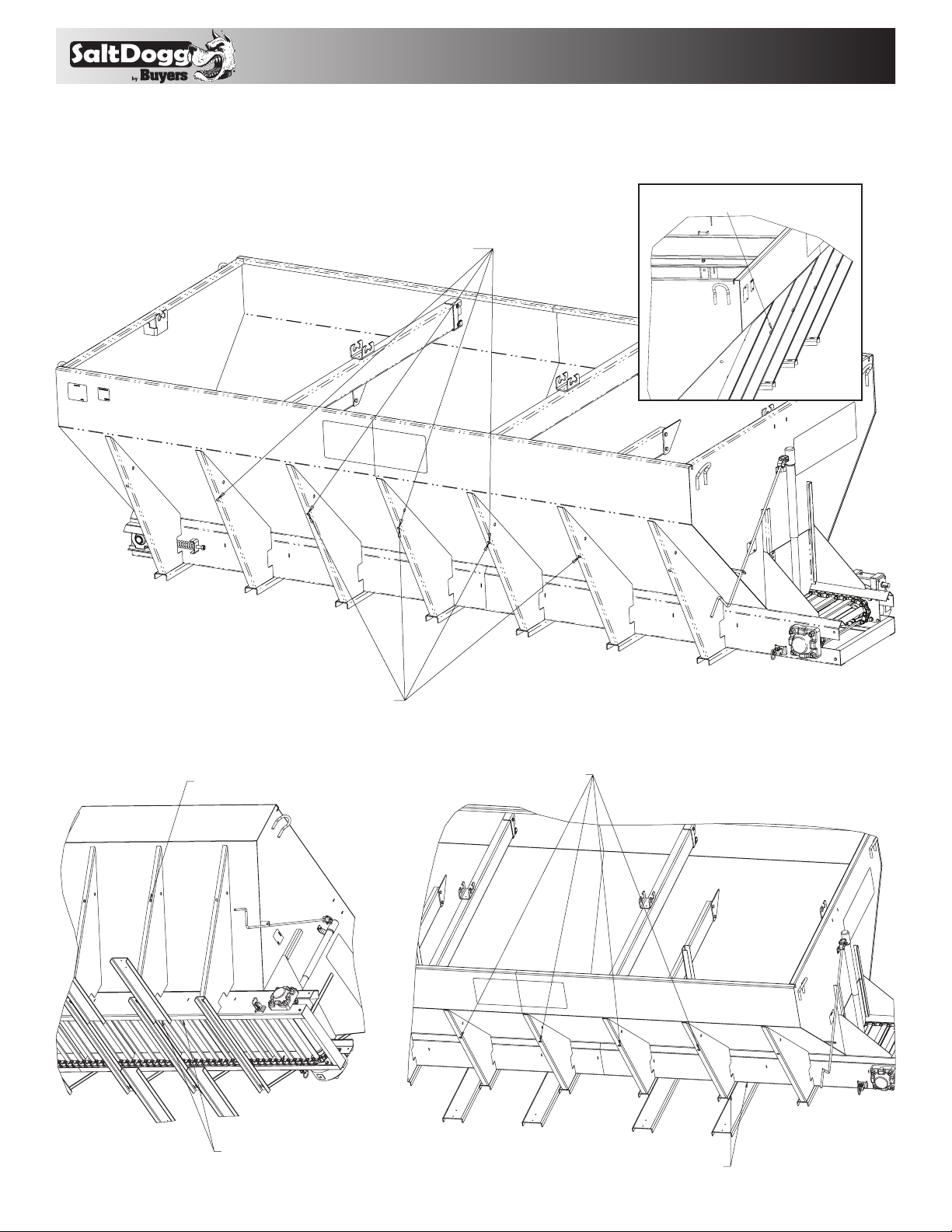
1. Position 1/2-13 projection weld nuts on inside gusset surface and weld them as shown in FIG 1
and FIG 2. Follow welding order for Installation A or Installation B.
ALIGN NUT IN THE HOLE. WELD AROUND NUT.
PROTECT THREAD FROM WELDING.
Fig. 1
FOR INSTALLATION A
Fig. 2
WELD PROJECTION WELD NUTS IN THESE LOCATIOS
2. Align channels #3026808 to hopper sill bottom edge and clamp to hopper cross channels. See
FIG 3 for channels positions and welding recommendations.
REAR MOST NUT
ALIGN CHANNEL EDGE WITH
SILL EDGE. CLAMP CHANNELS
IN THIS POSITION
Fig. 3
WELD CHANNEL TO HOPPER
2
9049 Tyler Blvd. • Mentor, Ohio 44060
GRIND OFF EXCESSIVE WELDS, IF NECESSARY
INSTALL TANKS AS SHOWN
Phone (440) 974-8888 • Fax (800) 841-8003
www.saltdogg.com
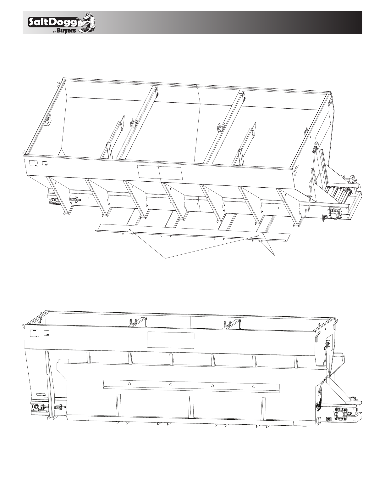
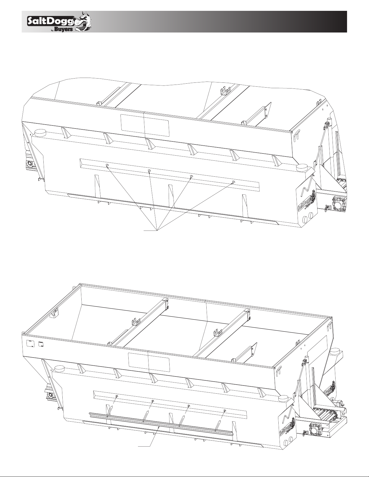
3. Align holes in retainer #3026545 with holes in channels #3026808 and weld retainers to channels
as shown in FIG 4.
Fig. 4
ALIGN HOLES IN CHANNELS AND RETAINERS
WELD RETAINERS TO EVERY CHANNEL.
4. Install tanks #3026538 on retainers aligning 4 holes in tanks with nuts wedded to gussets FIG 5.
Fig. 5
3
9049 Tyler Blvd. • Mentor, Ohio 44060
LEAVING ABOUT 1 INCH EXPOSED.
PASS THREADED RODS THRU TUBES.
Phone (440) 974-8888 • Fax (800) 841-8003
www.saltdogg.com
5. Apply thread locker on threaded rods #3026587. Pass rods thru tank holes and screw them into
welded nuts. Leave rods sticking out about 1 inch from tank surface FIG 6.
Fig. 6
APPLY THREAD LOCKER ON THREADED ROD.
ASSEMBLY THREADED RODS INTO WELDED NUTS,
6. Insert retainer #3026545 into tank holes. Pass threaded rods thru tubes FIG 7.
Fig. 7
INSERT RETAINERUPPER INTO TANK OPENINGS AS SHOWN.
4

Phone (440) 974-8888 • Fax (800) 841-8003
SECURE RETAINER USING 1/2 INCH WASHERS AND NUTS.
7. Secure retainer using 1/2 inch flat washers and nylon insert nuts FIG 8.
Fig. 8
9049 Tyler Blvd. • Mentor, Ohio 44060
www.saltdogg.com
8. Weld enclosure bracket #3028485 in desired location based on Installation A or B style. If space is
limited custom bracket fabrication is necessary.
9. If jack handle is rubbing against tank or other obstacle, it can be relocated using supplied handle
guide #3026823. To relocate handle it must be disassembled from jack, pass thru handle guide and
reassembled to jack FIG 9. After these operations, handle guide can be positioned and welded in
new location. Make sure that jack is operating freely after handle reposition!
JACK HANDLE CAN BE
REPOSITIONED USING SUPPLIED
ATTACH ENCLOSURE TO
BRACKET
ATTACH ENCLOSURE BRACKET.
DIFFERENT LOCATIONS CAN BE USED.
5

9049 Tyler Blvd. • Mentor, Ohio 44060
Phone (440) 974-8888 • Fax (800) 841-8003
www.saltdogg.com
10. Assembly enclosure assembly LS102 to bracket, making sure that enough space left to open
enclosure door.
11. Plumb: Reservoir, ball valve, filter, pump enclosure, and spray nozzles according to plumbing
schematic using supplied fittings, hose, and hose clamps. Do not use Teflon tape on threads. Use
liquid thread sealant.
12. In order to install liquid spray nozzles, 2 holes 11/16" diameter must be drilled in chute. Or
nozzles can be installed above spreader conveyor chain ( some custom bracket fabrication is
required).
Cab Controller Installation Instructions FIGs 10-12
1. Install cab controller (#WSE1) in cab for convenient driver operation. Mounting bracket and fasteners included.
WSE25
25' Cable Connector
Fig. 10 WSE1 Cab Controller, front view Fig. 10 WSE1 Cab Controller, rear view
8' Cable Connector
WSE24
2. Route 8' wire harness (#WSE24) under dash from controller (#WSE1) to truck’s fuse panel.
3. Ground “black” wire from controller to truck frame or truck’s battery (not dash).
4. Attach “green” wire in 8' wire harness (#WSE24) to a fused and keyed 15 Amp hot wire circuit.
5. Connect main power “white” wire in 8' wire harness (#WSE24) to fuse box that is “hot” full time or
to battery “positive”.
6. Route the 25' wire harness (#WSE25) from the rear of the spreader to the cab. Plug connector on
controller (#WSE1) to the connector on pump harness (#WSE25).
Fig. 7
6

Fig. 11 Plumbing Diagram
9049 Tyler Blvd. • Mentor, Ohio 44060
Phone (440) 974-8888 • Fax (800) 841-8003
www.saltdogg.com
Reservoir
#3010816
Ball Valve #WSE10
Filter #WSE11
Pump Enclosure #WSE22
Reservoir
#3010816
Ball Valve #WSE10
Filter #WSE11
25' Harness
#WSE25
Pump #WSE3
Pressure Switch #WSE4
Spray Nozzles
Controller
#WSE1
8' Harness
#WSE24
7

Phone (440) 974-8888 • Fax (800) 841-8003
Fig. 12 Nozzle Assembly
WSE9 WSE9 WSE9
WSE34 WSE13
9049 Tyler Blvd. • Mentor, Ohio 44060
www.saltdogg.com
WSE 6168 WSE6065
WSE33 WSE33WSE33
3000269
WSE7
WSE15
WS E14
3000269
WSE7
WSE15
WS E14
from
3010 816
WSE2
WSE10
Fig. 13 Filter/Valve Assembly
WSE2 WSE30
WS E 11
8
WSE9
WSE 6168
to
WSE22

9049 Tyler Blvd. • Mentor, Ohio 44060
Phone (440) 974-8888 • Fax (800) 841-8003
www.saltdogg.com
Liquid Spray System Operating Instructions
1. Read all instructions before operating. Always
wear hand, eye, and skin protection when
working with de-icing chemicals. Make sure
everyone is standing clear of liquid spray system
before operating.
2. Inspect all plumbing for leaks.
3. Open ball valve (#WSE10) at the reservoir.
4. Make sure reservoir has adequate supply
of clean de-icing liquid. Do not operate pump
without liquid.
5. Before turning the cab controller on, turn the
black speed control knob counter clockwise until
it stops to set the pump at the slowest speed.
6. To energize system, turn red power button to
illuminate LCD screen “on” position.
7. Increase pump speed to desired liquid spray
application rate by turning black knob clockwise.
8. If the red low pressure warning light/alarm
comes on, the reservoir is empty or the pump is
off. Do not operate pump without liquid. Note:
Low pressure light and alarm will sound each
time system is started. This is normal and
occurs until sufficient pressure is achieved to
open pressure switch (turning off light/buzzer).
9. Close ball valve (#WSE10) at the reservoir
when not in use.
Liquid Spray System Trouble Shooting Guide
Motor & Pump Operate Erratically: 1,2,3,4,5 (Possible Problem)
Motor runs – Pump does not: 1,2,3,4,5,6,7 (Possible Problem)
Motor & Pump fail to operate: 8,9,10,11,12 (Possible Problem)
POSSIBLE PROBLEM: REPAIR:
1. Little or no de-icer in tank/s Fill
2. Clogged filter Clean
3. Clogged Nozzles Clean
4. Damaged suction hose Replace
5. Ruptured pump diaphragm Replace
6. Ball valve is closed at tank/s Open valve
7. Frozen parts Thaw out
8. Bad electrical connection Inspect
9. Motor failure- burned/seized Replace
10. Cab controller on-off switch not turned on Turn on
11. Bad cab controller on-off switch Replace
12. Blown fuse in cab controller or fuse panel Inspect/replace
CAUTION
Always wear hand, eye, and skin protection when working with
de-icing chemicals. Use extreme care!
Liquid Spray System Routine Maintenance
RESERVOIR:
-Inspect fittings for leaks from cracks or
looseness
-Inspect filler/breather for cracks. Depress
breather to check for adequate spring pressure
or binding
PLUMBING:
-Inspect hoses/fittings/ball valve for leaks,
cracks, looseness, chafing, binding etc.
FILT ER:
-Remove and clean filter element every 8 to 10
hours or as needed depending on how clean
de-icing liquid is
PUMP-PRESSURE SWITCH & ENCLOSURE:
-Inspect wiring for wear and loose or corroded
connections
-Inspect door and gasket to prevent corrosion
NOZZLES:
-Inspect operation for even spray pattern.
Remove and clean as needed
CAB CONTROLLER:
-Inspect lights, switch, and flow control knob
-Inspect wire harness and connections for wear
and loose or corroded connections
CLEANING:
-Wash with hot water and soap after each use
STORAGE:
-Store inside to prevent freezing
-Drain liquid de-icer from tank/s and hoses
when not in use for more than two days or
during extremely low temperatures
-RV anti-freeze or windshield washer fluid should
be run through the system for several minutes
to flush de-icer from the system to prevent
component freezing especially for end of season
storage
CAUTION
Always wear hand, eye, and skin protection when working with
de-icing chemicals. Use extreme care!
9

LS10
8
9049 Tyler Blvd. • Mentor, Ohio 44060
Phone (440) 974-8888 • Fax (800) 841-8003
www.saltdogg.com
7
15
9
Bill of Materials
ITEM PART NO. QTY. DESCRIPTION
1 LS102 1 ENCLOSURE ASSY, WETTING SYST
2 3012164 1 PLUG, SQUARE HEAD, 3/4 NPT
3 3000269 12 WASHER, FLAT 1/2 USS, SST
4 WSE15 2 RUBBER, NOZZLE
5 FWL050088013SS 3 WASHER, LOCK - 1/2 SPLIT SST
6 FNH050013041HSS 3 NUT, 1/2-13 HEAVY HEX, SST
7 3026538 2 TANK 400 GAL POLY
8 3026808 8 CHANNEL
9 3026807 2 RETAINER
10 3026587 8 TREADED ROD 1/2-13 SST
11 3026545 2 RETAINER, UPPER
12 3014454 8 NUT, 1/2-13 PROJECTION WELD SST
13 FNE050013053SS 8 NUT, NYLOCK 1/2-13 SS
14 3026823 1 GUIDE, HANDLE JACK
15 3028485 1 BRACKET, ENCLOSURE
WSE2 4 NIPPLE, HEX 3/4 X 1/2 POLY
2
3
4
5
6
10 11
14
ITEM PART NO. QTY. DESCRIPTION
WSE10 2 VALVE BALL, 1/2 NPT, POLYPROPYLENE
WSE11 2 FILTER, 3/4 NPT, 6 GPM, 300 MICRON,POLY
WSE13 2 ELBOW, BRASS 1/4 NPTF X 1/4 NPTF
WSE14 2 NOZZLE CAP
WSE24 1 HARNESS, WIRE W/ CONNECTOR 8 FT
WSE30 2 BARB,HOSE 3/4 MNPT X 1/2 HB
WSE696 1 HOSE POLY 1/2 X 96 IN
3000165 1 LABEL, 1" X 3" ADHESIVE
3009750 1 DECAL, LIQUID SYSTEM
WSE33 6 BARB,HOSE 1/4 MNPT X 1/2 HB, BRASS
WSE34 2 TEE,1/4 FNPT X 1/4 FNPT X 1/4 FNPT,BR ASS
WSE6168 1 HOSE POLY 1/2 X 168 IN
1
WSE7 2 NOZZLE BODY, BRASS
WSE9 10 CLAMP, HOSE
WSE1 1 CONTROLLER, WET SPRAY SYSTEM
12
13
10

9049 Tyler Blvd. • Mentor, Ohio 44060
Phone (440) 974-8888 • Fax (800) 841-8003
www.saltdogg.com
SAFETY ALERT SYMBOL
This Symbol Means
Please Read & Understand Completely
Before Operating!
EQUIPMENT INSTALLERS & OPERATORS:
TURN OFF ALL POWER BEFORE PERFOM ING
ANY SERVICE OPERATIONS.
• Follow Recommended Operating Procedure.
• Keep Equipment In Safe Operating Condition
At All Times.
• Recognize & Avoid Hazards While Operating,
Servicing and Maintaining Equipment.
ATTENTION!
CAUTION
RESERVOIR & COMPONENTS
MAY CONTAIN HAZARDOUS
MATERIAL.
HANDLE WITH CARE.
WARRANTY
Buyers Products Co. warrants all truck /trailer hardware manufactured or distributed by it, to be free from defects in material and
workmanship for a period of one year from date of shipment. Parts
must be properly installed and used under normal conditions.
Any product which has been altered, including modification, misuse, accident or lack of maintenance will not be considered under
warranty. Normal wear is excluded. The sole responsibility of Buyers
Products Co. under this warranty is limited to repairing or replacing any
part or parts which are returned, prepaid, and are found to be defective
by Buyers Products Co. Authorization from Buyers Products Co. must
be obtained before returning any part. No charges for transportation
or labor performed on Buyers’ products will be allowed under this
warrant y.
11
3027062 Rev. C
 Loading...