

TM
Instruction Manual
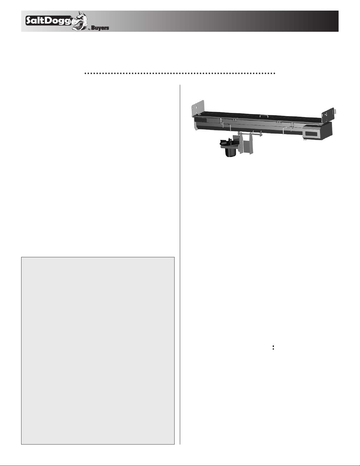
Under Tailgate Spreaders
Electric 12 VDC
92440SSA
Table of Contents
Warranty Information ............................................... 1
Spreader Installation Instructions ........................ 1,2
Spreader Installation Drawing ................................. 2
Spinner Assembly Instructions ..............................3,4
Spinner Assembly Drawing ...................................3,4
Operating Instructions ...........................................5,6
Recommended Maintenance .................................... 6
Parts list .................................................................... 7
Parts List: Hardware Box ......................................... 8
Spinner Components Drawing ................................. 8
UNDER TAILGATE SPREADER WARRANTY
This warranty replaces all previous warranties and no employee
of this company is authorized to extend any additional warranties,
or agreements, or implications not explicitly covered herein.
Buyers Products Company warrants all par ts of the product to
be free from defects in material and workmanship for a period of
(1) one year from the date of original installation. Parts must be
properly installed and used under normal conditions. Normal wear
is excluded.
Any part which has been altered, including modification, misuse,
accident, or lack of maintenance will not be considered under this
warranty. The sole responsibility of Buyers Products Company
under this warranty is limited to repairing or replacing any
part(s) which are returned, prepaid, 30 days after such defect is
discovered, and returned par t(s) are found to be defective by Buyers
Products Company.
Authorization from Buyers Products Company must be
obtained before returning any part. The following information
must accompany defective parts returned to Buyers Products
Company: RMA#, spreader model, serial number, date installed,
and distributor from whom it was purchased. Buyers Products
Company shall not be liable for damage arising out of failure of
any unit to operate properly, or failure, or delay in work, or for any
consequential damages. No charges for transportation or labor
performed on any part will be allowed under this warranty.
9049 Tyler Blvd. • Mentor, Ohio 44060
Phone (440) 974-8888 • Fax (440) 974-0165
Toll-Free Fax 800-841-8003 • saltdogg.com
Installation Instructions
NOTE: The left and right end plates may, on
occasion, get bent through improper handling
during shipment or storage. If this should happen, square and true the left and right end plates
before installation.
1. Aligning the spreader:
A. Position the spreader with the truck such that
the auger gear motor is located on the right side of
the truck (passenger side).
B. Lift the spreader up and under the dump body
tailgate, positioning the spreader forward as close
as possible to the dump body. The tailgate of the
dump body should lay down horizontally over the
spreader.
C. Support the spreader solidly and securely when
positioning for mounting.
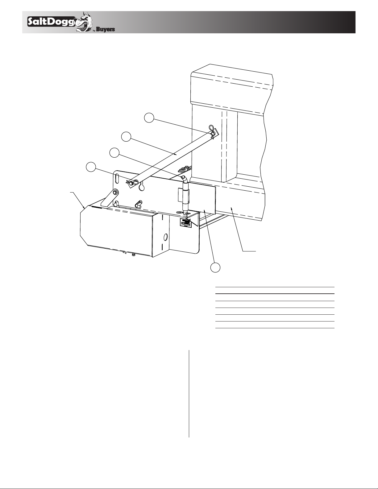
2. Attach mounting brackets (See Fig. 1.)
A. Attach a quick detach plate, (1) to both sides of
the spreader frame using hinge pins (2) and a hairpin cotter pins (5).
B. Position the (2) quick detach plates over the
dump body rub rails and flush with rear edge of
dump body.
C. Weld the quick detach plates to the dump body
rub rails. Weld the plates continuously around 3
sides of each plate. Do not weld along the edge of
the plates next to the attachment pin.
1
—c ontinued inside
SPREADER
TM
Mounting Hardware Installation Drawing
Figure 1
4
3
2
5
D. Align the pin brace (4) on the dump body using
the iron brace (3) for exact positioning. For proper
fit, hanger iron brace may require some minor
bending.
E. Weld the pin braces (4) to the dump body sides,
all around.
F. Attach the iron braces (3) to the pin braces on
the sides of the dump body and the sides of the
spreader using two hairpin cotter pins (Item 5).
DUMP BODY
1
Bill of Materials
item qty. description
1 2 Quick Detach Plate 3009526
2 2 Hinge Pin 3011139
3 2 Hanger Iron Brace 3011137
4 2 Pin Brace 3000210
5 6 Hair Pin Cotter 5/32" –
G. If there is a gap between the spreader and the
dump body, weld or bolt a steel strip to the forward
edge of the spreader to cover the gap.
H. If you have purchased the tailgate side shields
(purchased separately as P/N 924F0106), bolt or
weld them to the inside of the tailgate to prevent
material spillage at the ends of the spreader.
2
TM
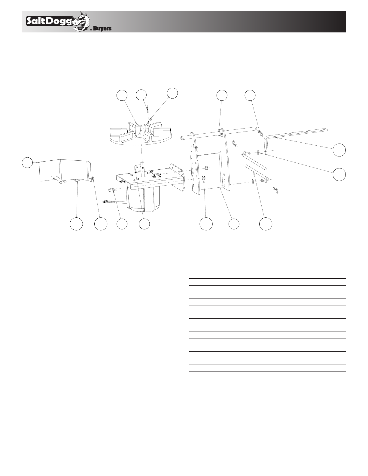
2. Spinner assembly installation:
Figure 2
4
7
9 10 11 12 13
6
3
5
2
8
15
14
1
A. Attach heights adjustment bracket (1) to
spreader lower tray using rod hinge (2) and hair
pins.
B. Attach spinner motor assembly (3) to heights
adjustment bracket (1) using ½-13 screws and nuts.
C. If extra clearance required, use upper holes in
heights adjustment bracket.
D. Attach spinner shield (7) to heights adjustment
bracket (1) using 5/16-18 screws and nuts.
E. Attach spinner disk (4) to motor shaft using
clevis pin and cotter pin.
Bill of Materials
item qty. description
1 1 Bracket Heights Adj. Weldment 3017175
2 1 Rod, Hinge 3006646
3 1 Bracket Spinner Motor Assembly 3017176
4 1 Spinner, 14" Poly CCW 3016394
5 1 Pin, Clevis, 5/16 x 2-1/2, .141 Hole ZN –
6 1 Cotter Pin, 1/8 x 1, Zinc –
7 1 Shield Spinner Disk 301717 2
8 4 Pin, Hair Cotter 5/32" ZN 3.25 OAL –
9 2 Screw, HHC 1/2-13x1.50 SST –
10 2 Nut, Nylock 1/2-13 Zinc –
11 3 Screw, Hex HD, 5/16-18 x 3/4 GR5 SS –
12 3 Nut, Hex Flange - 5/16-18 SS –
13 2 Weldment, Parallel Linkage 924F 0 012
14 2 Washer, Flat 1/2 ID SST –
15 1 Angle, Spinner Lug 3006645
3

TM
PARALLEL
LINKAGE HOLE
D
D1
L
L1
D
D1
L
L1
PARALLEL
LINKAGE HOLE
Figure 3
J. Keeping the spinner assembly level, secure the
spinner frame in place using the set screw or 5/1618 hex screw.
3. Control Box and Vehicle Wiring Harness Installation
MAKE SURE YOU HAVE CONNECTED THE PROPER WIRE COLOR.
THIS IS WIRE GROUND ELECTRICAL SYSTEM! NO
CONNECTIONS TO TRUCK’S FRAME OR BODY ALLOWED!
WARNING
WARNING! Do not drill holes into fuel tanks, fuel lines,
through electrical wiring, etc that may be damaged by
drilling. To insure good performance of your spreader,
check the condition of truck’s electrical system. Using
digital voltmeter, check alternator and battery voltage.
With engine running and head lights and heater fan ON
good voltage reading should fall between 13.0 and 15.3
volts. If voltage reading falls out of this range, check and
adjust your electric system.
Figure 4
F. The leveling mechanism may now be mounted.
Park truck on flat, level surface. With spinner
assembly in level position, carefully measure “L”
and “D” distances. Use any of 3 available holes in
heights adjustment bracket. Locate angle (15) such
that ½” hole will position with D1=D and L1=L.
Modify angle if necessary.
G. Secure angle (15) to the truck frame.
H. Attach parallel linkage rods (13) to heights
adjustment bracket and angle. Secure them using
½” washers and hair pins.
I. Clamp parallel linkage rods together. To verify
leveling action, slowly raise the dump. Be sure that
spinner motor assembly and linkages do not have
any interference with truck body and it does not
have contact with the road. After checking weld
parallel linkage bars together.
NOTE: Always disconnect battery before attempting to
install electrical components on your vehicle.
A. Mount the controller in a convenient location in the truck
cab. It is recommended not to mount the controller directly in
front of heat vents. Allow ample air space around controller.
CAUTION
DO NOT MOUNT CONTROLLER IN THE WAY OF AIR
BAG DEPLOYMENT!
B. Route both wire harnesses into truck cab through firewall
(it maybe necessary to drill holes). Insulate hole to avoid
water leaks.
C. Insure no wires are nicked or damaged during
installation.
D. Connect the 4-pin connector on the wire harness to the
control box 4-pin connector.
E. Connect the 2-pin connector on the power cable to the
control box mating connector.
F. Connect wire harness single connectors to control box
connectors.
G. Connect fuse connector to the fuse terminal or ignition
switch (5 AMP max).
H. Lay out a path for the power cable to the battery, use
quick ties to secure power cable.
DO NOT CONNECT TO BATTERY AT THIS TIME!
I. Lay out path for wire harness to the rear of the vehicle. It
is recommended to stay clear of the exhaust system. Excess
heat can damage the wire harnesses. Use quick ties to
secure harness to underbody.
J. Connect the wire harness to the motor. Make sure wire
colors on wire harness match colors on the motor.
4

TM
CONNECT TO BATTERY
TERMINALS ONLY
CONNECT TO FUSE OR WIRE
IN FUSE PANEL CONTROLLED
BY IGNITION SWITCH
5 AMP MAX
CONNECT TO CHAIN/ AUGER
CONNECT TO
CHUTE MOTOR
#0203700
GEAR MOTOR
#3016943
CONNECT TO VIBRATOR
OPTIONAL
CONNECT
#3016944
CONNECT
CONNECT
#3016934
CONTROLLER
Thoroughly clean battery terminals. Make sure battery
terminals have no tarnish or corrosion. DO NOT CONNECT
WIRE HARNESS TO DAMAGED OR CORRODED
TERMINALS!
IT MAY RESULT IN OVERHEATING, LOST POWER AND
POTENTIAL CONTROLLER DAMAGE!
K. Connect the power cable directly to the battery.
L. Insure all functions of the controller are
working properly.
M. Observe auger moving in proper direction. If direction is
wrong reverse wires between Motor and Wire Harness.
N. Optional spot light (5 AMP max) can be installed on
spreader. Remove cap from single white wire. Connect light
to this wire and trucks frame.
IM PO RTA N T
CONNECT
CONNECT
IMPORTANT Make sure all wires securely attached to
vehicle or spreader. Use wire ties and/or wire clamps
to attach wires. All excess wires must be rolled into
bungles and attached to vehicle or spreader.
ATTACH WIRE HARNESS TO LOWER
DOOR USING CLAMP HK1113 AND
WING NUT 3005723. LEAVE ENOUGH
WIRE SLACK TO PLUG CONNECTORS
5
TO GEAR MOTOR.
Figure 5

TM
Spreader Assembly Parts List
22
29 30 31 32 33 34
23
26
1
7
6
17
24 25
12
13
10
8
20
19
18
11
14
44
9
28
27
3
5
2
4
36
Bill of Materials
item qt y. descr ipti on pArt no.
1 1 Frame, Welded, 96 UTS SS 3015 029
2 1 Tray, Lower Weldment, SS 96 UTS 3015 033
3 2 Latch, Cover HNG MTG BRKT 300 8447
4 1 Rod, Latch, UTS Tray SST PS 3019 033
5 1 Rod, Latch, UTS Tray SST DS 3019 032
6 1 Gasket, Felt Bearing 9240087
7 1 Bearing, 1-1/4 Flange 2 Hole 9240086
8 1 Adapter, Gear Motor, Weldment 3014455
9 1 Bearing, Flanged 1-1/8" 141020 0
10 2 Screw, HCAP 7/16-14 x 1.25 SST –
11 2 Nut HEX NYLOCK 7/16-14 SST –
12 3 Washer, Flat 1/2 USS, SST –
13 3 Screw, HHC- 1/2-13 X 1 SST –
14 1 Gear Motor Conveyor 12 VDC 3013821
15 12 Washer, Flat 3/8 USS SST –
16 15 Screw, HHC 3/8-16 x 1 304 SST –
17 1 Weldment, 96 UTS Auger 924F0081
18 1 Sleeve, Auger Adapter 3 014 858
19 1 Screw, HHC - 1/2-13 x 3 SST –
20 1 Nut, Nylock 1/2-13 Zinc –
21 11 Nut, Nylock 3/8-16 SST –
22 6 Nut, Hex FLNG 3/8-16 SST –
38 39 40 41
item qt y. descr ipti on pArt no.
23 1 Plate, Spinner Cover 3000270
24 2 Nut NYLOCK 5/8-11 SST –
25 2 Screw, HHC - 3/8-16 X 3.5 SST –
26 5 Pin, Hair Cotter, Clear Zinc .091 x 2 –
27 1 Decal, #1, Danger Stay Clear 9240131
28 2 Screw, HHC - 3/8-16 X 1.25 SST –
29 1 Plate, Auger Cover 3014897
30 4 Pin, Clevis 3/8 x 1.125 SST –
31 1 Weldment, Cover, 96IN UTS SST 3012956
32 2 Bracket, SST Cover Latch w. Holes 3006968
33 2 Handle, Stainless Steel Locking 3000268
34 1 Decal, Salt Dogg, BLK/WHT on CLR 3011132
35 1 Cover, Gear Motor Weldment 3017187
36 2 Screw, HHC - 5/16-18 X 5/8 SST –
37 1 Cover Side Gear Motor 301718 6
38 2 Bracket, Receptacle SZ8 Deutsch
39 2 Screw, HHC - 3/8-16 X 1.25 SST –
40 1 Plug 1.00' Dome Heyco 1702 3017483
41 2 Bushing Strain Relief Heyco 2047 3017482
42 3 Screw #12-14x. 74 SS 3015 873
43 1 Decal #2, Danger Before Svce
44 1 Motor Replacement for 3013821
21
43
35
42
37
16
15
3017121
9240132
3014778
6

TM
Hardware Box Parts List
15
10
2
1
11
5
4
14
8
6
7
9
12
13
Bill of Materials
item qt y. descr ipti on pArt no.
1 1 Bracket Spinner Motor Assy. 3017176
2 1 Spinner Shield Disk 3 017172
3 1 Spinner, 14" Poly CW 3016394
4 2 Weldment, Parallel Linkage 92 4F0 012
5 1 Rod, Hinge 3006646
6 1 Angle, Spinner Lug 3006645
7 2 Bracket, Hanger, UTS SST 3011137
8 2 Plate, Detach, Mount SST 3009526
9 2 Pin, Hinge, SST 3011139
10 1 Hardware Bag, UTS Electro 3015181
11 1 Controller Speed 12 VDC, 60 AMP 3016934
12 1 Wire Harness, Main 301694 4
13 1 Power Cord 3016943
14 1 Wire Assembly, 36 Long 0203700
15 1 Bracket Heights Adj. Weldment 3017175
1 Instruction Manual, UTS Electro 3017501
3
7

9049 Tyler Blvd. • Mentor, Ohio 44060
TM
Phone (440) 974-8888 • Fax (440) 974-0165
Toll-Free Fax 800-841-8003 • saltdogg.com
Spreader Motor Assembly
3
1
2
6
4
5
Bill of Materials
item qt y. descr ipti on pArt no.
1 1 Bracket Weldment, Spinner Motor 3017171
2 1 Motor 12 VDC, .5 HP Spinner 3016309
3 4 Screw, HHC 3/8-16 x 1 304 SST –
4 1 Cover, Motor, Drilled 3017174
5 3 Screw, Cap 1/4-20 x 3/4 SST –
6 1 Wire Harness, Chute 3006753
8
30175 01 Rev. C
 Loading...