

TM
Instruction Manual
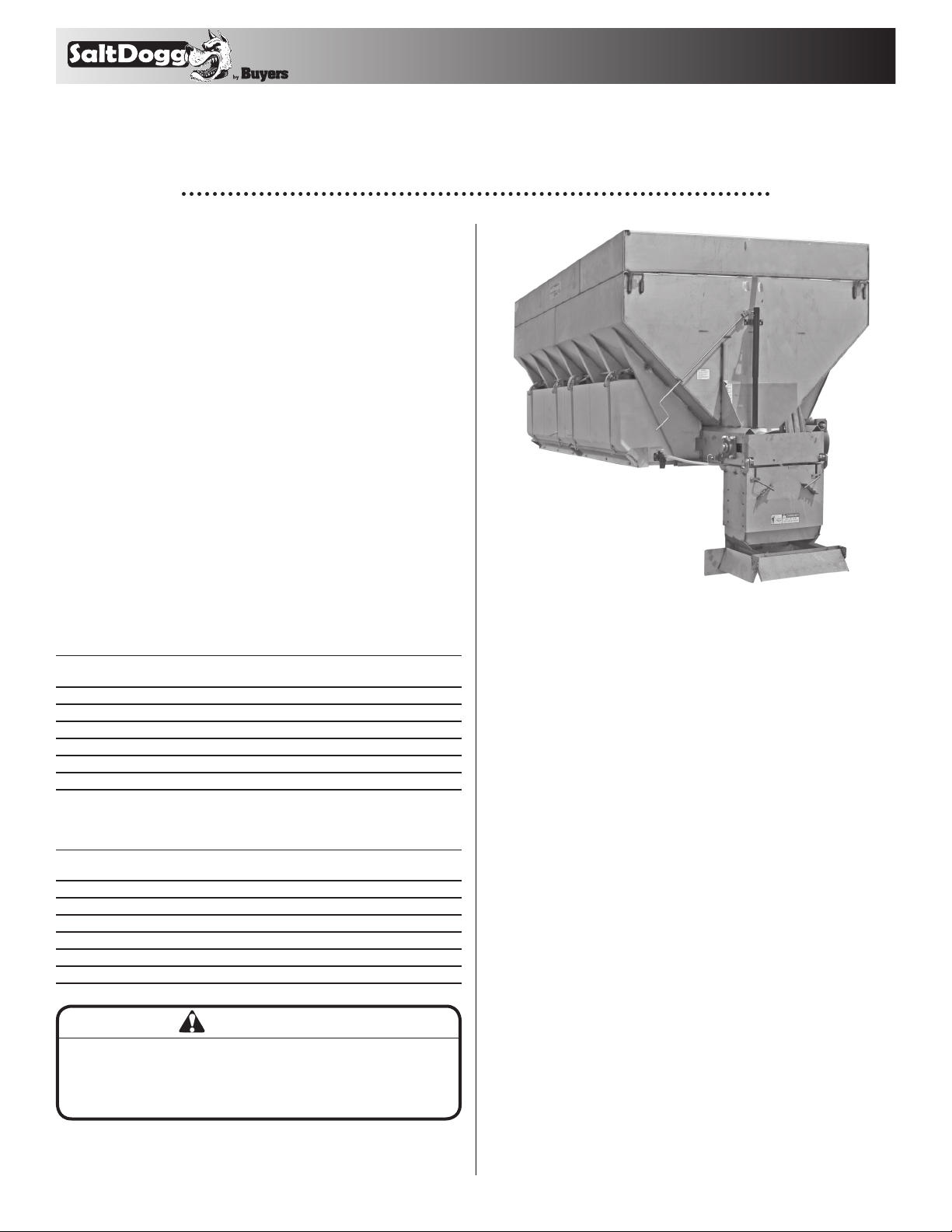
Municipal-Sized Hydraulic
Powered Stainless Steel Hopper
Spreaders
Table of Contents
Warranty Information .............................. back cover
General Information .................................................1
Safety Precautions ................................................1-2
Installation Instruction .........................................2-8
Spreader Operation ...............................................2-8
Spreader Maintenance ..........................................2-8
Repair Parts .......................................................... 6-8
Optional Equipment .................................................5
9049 Tyler Blvd. • Mentor, Ohio 44060
Phone (440) 974-8888 • Fax (440) 974-0165
Toll-Free Fax 800-841-8003 • saltdogg.com
Shown with
Optional LS4
Liquid Spray
System
General Information
SPREADERS- 34,000 lb. to 38,000 lb. GVW Chassis
hoPPer LenGTh : 144" overaLL LenGTh: 167" WidTh: 82"
Gear box Leve L round ed side eMPT Y
ParT no. r aTio cu. Yr ds. cu. Yrds. heiG hT WT. Lbs.
1451057SSH 50:1 8.76 10.00 57" 2990 LBS.
1421057SSH 25:1 8.76 10.00 57" 2990 LBS.
1451163SSH 50:1 10.28 11.82 63" 3155 LBS.
1421163SSH 25:1 10.28 11.82 63" 3155 LBS.
1451369SSH 50:1 11.82 13.59 69" 3260 LBS.
1421369SSH 25:1 11.82 13.59 69" 3260 LBS.
SPREADERS- 48,000 lb. to 60,000 lb. GVW Chassis
hoPPer LenGTh : 168" over aLL LenGTh: 191" WidTh : 82"
Gear box Leve L round ed side eMPT Y
ParT no. r aTio cu. Yr ds. cu. Yrds. heiG hT WT. Lbs.
1451257SSH 50:1 10.22 11.75 57" 3570 lbs.
1421257SSH 25:1 10.22 11.75 57" 3570 lbs.
1451363SSH 50:1 12.00 13.80 63" 3930 lbs.
1421363SSH 25:1 12.00 13.80 63" 3930 lbs.
1451469SSH 50:1 13.80 15.87 69" 4040 lbs.
1421469SSH 25:1 13.80 15.87 69" 4040 lbs.
IMPORTANT
Consult federal, state and local weight laws and chassis
manufacturer’s ratings to ensure neither government weight
restrictions, nor GVWR and GAWRs are exceeded.
2. Average Material Weights
MATERIAL WEIGHT (POUNDS PER CUBIC YARD)
#1 Rock Salt - 950
#2 Rock Salt - 1,215
Coarse Sand - Dry 2,565
Coarse Sand - Wet 3,240
3. Recommended Fastener Torques
Maintain all fastener torques as shown in the following table. Failure to do so may cause injury to
persons.
SAE GRADE 2 SAE GRADE 5
ft-lbs ft-lbs
5/16-18 11 18
3/8-18 19 31
3/8-24 24 46
7/16-14 30 50
1/2-13 45 75
9/16-12 66 110
5/8-11 93 150
4. Gearbox Oil
The gearbox of the spreader is filled with ISO VG
460 synthetic gear lubricant at the factory. This
lubricant has operating temperature -40º C to
150ºC.
1
—continued inside

TM
WARNING
Verify that the above oil meets your operating temperature requirements. If not, empty and refill with
the proper viscosity oil. Before starting spreader,
check that the gearbox is filled to the proper level
with lubricant.
General Safety Precautions
WARNING
Observe the following Safety Precautions before,
during and after operating this spreader. By following these precautions and common sense, possible
injury to persons and potential damage to this
machine may be avoided.
1. Read this entire Owner’s Manual before operating this spreader.
2. Read all safety decals on the spreader before
operating the spreader.
3. Check to make sure all safety guards are
securely mounted into place before operating your
spreader.
4. Verify that all personnel are clear of the
spreader spray area before starting or operating
this spreader.
5. Keep all loose clothing, hair, jewelry and limbs
clear of the spreader before starting or operating
this spreader.
6. Do not over-load your vehicle beyond payload
limits.
7. Do not perform any service operation on the
spreader while it is running.
8. Do not climb on or into the spreader during
operation.
9. Do not ride on the spreader while the vehicle is
in motion.
10. Make sure the spreader is securely fastened to
the vehicle.
11. Do not operate a spreader that is in need of
maintenance or repair.
General Installation Instructions
Dump Body Mounting
1. Remove the tailgate from the vehicle if
applicable.
2. Lift the spreader using the (4) lifting loops in the
corners of the hopper.
WARNING
The lifting device must be adequately rated to lift
a payload equal to or greater than the spreader
weight. See page 1 for spreader weights. Empty the
spreader before lifting.
3. Center the spreader in the vehicle. Spreader
sills must overhang 20” beyond the back end of
the vehicle.
4. If the dump body is not flat, it is suggested that
the spreader be placed on two 1" x 6" hardwood
boards. This will evenly distribute the weight of
the loaded spreader on the entire cross channels.
5. The spreader may be secured to the vehicle by
using Tie-Down Kit Buyers part #3010548 (sold
separately).
6. Periodically check that the spreader mounting
hardware is securely tightened.
Chassis Mounting
1. Hardwood wear strips usually 1" x 3" (not furnished) must be fitted to the truck chassis.
2. The spreader should be positioned on the
wooden wear strips so hopper sills must overhang
20” beyond the back end of the vehicle.
3. In addition a distance of approximately 4"-6"
must be left between the truck cab and the front of
the hopper. This will help facilitate any future servicing of the conveyor chain.
4. Qualified installer must fabricate suitable
angles to attach hopper cross members to track’s
frame.
DO NOT weld mounting angles to the truck frame.
Doing so can cause fatigue cracking of the truck
frame.
2
TM
Chute Installation
1. Bolt chute to Chute Guide using screws,
washers and nuts. Place washers between Chute
Guide tabs and Chute brackets.
2. Swing chute towards vehicle. Connect chute
to the hopper by engaging two latches into corresponding holes in chute brackets.
3. Chute heights can be adjusted by sliding lower
chute assembly up or down inside of upper chute
assembly. Adjustment slots are spaced by 3".
Secure lower chute assembly using all 4 carriage
bolts provided. Make sure all four bolts are used for
installation.
.
Spreader Operation
The spread pattern and the amount of material dispensed will depend on the following factors:
• Conveyor speed.
• Spinner RPM.
• Feed gate door position.
• Baffle settings.
Below are illustrations that show the baffles effect
on the spread pattern as viewed from the top of the
spinner disk.
the dump body. Support long hoses with wire ties
or clamps.
3. Protect hoses from wear caused by sliding and/
or vibration.
4. For proper rotation of conveyor chain and
spinner motors, hoses may be reversed.
5. Note: Use of a pipe joint sealant compatible with
hydraulic oil is recommended for all screw fittings.
6. Use swivel type hose ends to connect hoses to
flow valve. Damage to valve body may occur if the
fittings in flow valve are over tightened.
7. A 10 micron return line filter is recommended
to protect the pump, valve, and motors from wear
causing contamination.
8. Spreader Operation
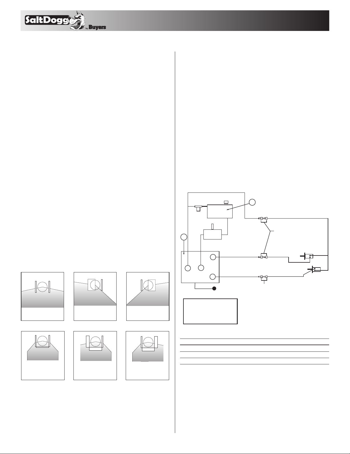
Initial Priming and Inspecting of the System
3/4" (1) Wire Ho se
1
10 Mircon
Filte r
3/4" (1)
Wire Ho se
Tank
Pump
3/4" (2) Wi re Hose
A
1-1/4" Spiral
Suct ion Hose
3/4" (2) Wi re Hose
2
1/2" (1) Wire Hos e
3/4" Quic k
Disco nnect s
Conve yer
1/2" (1) Wire Hos e
Chain Mo tor
Internal Baffle Adjustment
Both internal
baffles out
Left baffle in,
Right baffle out
Right baffle in,
Left baffle out
External Baffle Adjustment
All baffles adjusted
down for a confined
spread pattern
Right baffle deflects
material down;
heavy on right side
Left baffle deflects
material down;
heavy on left side
Installation Instructions – Hydraulic System
1. During assembly take precautions to keep all
hydraulic components as clean as possible.
2. Allow enough hose length to prevent kinking
and stretching of the hoses and to permit raising
P
T
Valve
ON/O FF Leve r
Valve Key
T= Tank/Reservoir
P= Pump/Pressure In
A= Auger (Conveyer Chain)
S= Spinner
1/2" (1) Wire Hos e
S
1/2" Quick D iscon nect s
(1) Single braid wire hose
(2) Double braid wire hose
1/2" (1) Wire Hos e
Spinne r Motor
Main Components
ite m part n o. qt y. descri ption
1 HV715 1 Dual Flow Regulator Valve
2 SMR15S 1 15-Gallon reservoir
N/S HVC1 1 Dual Flow Regulator Console
CAUTION
• Be sure everyone is standing clear of spreader.
• Be alert for anything that may require shutting
down the system.
• Before working in or around spreader equipment,
be sure all hydraulic controls are moved to OFF
position.
3

TM
1. Use high grade non-foaming hydraulic oil to fill
reservoir about 3/4 full.
2. Position valve on/off lever to OFF.
3. Move auger (conveyor chain) and spinner knobs
on the valve to the open position.
4. Engage PTO and circulate hydraulic oil for
several minutes to warm up.
5. Move valve on/off lever to ON.
6. Inspect hydraulic system for leaks.
7. Check conveyor chain and spinner to see if they
are working properly and rotating the correct direction. To reverse rotation, switch the hydraulic lines
at the motor.
8. Refill reservoir to 3/4 full.
9. Hydraulic system should now be ready for use.
Spreader Start-Up
1. Check feed gate opening and baffle positions
for desired material flow and spread pattern. See
Spreader Operation section.
2. Check to make sure that no loose parts or other
material are in hopper , on in chute or spinner disk.
3. Shut off spinner and conveyor chain knobs and
position the on/off lever to ON. Engage the PTO
and allow the hydraulic system to warm up.
4. After the system is warm turn the spinner
and auger (conveyor chain) knobs to the desired
settings.
5. Changing the conveyor chain and spinner
speeds as well as adjusting the baffle positions
will produce various spread patterns.
Miscellaneous
• Valve setting changes may be made with truck
in motion.
• By moving on/off lever to the off position,
spinner and conveyor chain may be stopped at the
same time without changing their valve settings.
Caution
Always follow the following precautions so as not
to cause damage to the spreader.
• If the conveyor chain does not move because
of dense material or a material jam, remove all
material from the hopper and free the chain.
• If the material in the hopper freezes, move the
spreader into a warm area to thaw.
• To prevent the feed chain from freezing, do not
store material in the spreader.
• The gearbox is designed to only accept
torque from the input shaft. Therefore, DO
NOT ATTEMPT TO FREE THE CONVEYOR BY
USING A PIPE OR SIMILAR TOOL TO MOVE OR
DISLODGE THE CHAIN. This action will void all
warranties.
Spreader Maintenance
• Grease the following components regularly:
• Idler shaft bearings (2)
• Drive shaft bearing (1)
• Feed Gate Jack
• Gearbox input shaft (if equipped with fitting)
• Check gearbox oil level periodically and main-
tain the oil level by adding appropriate lubricant.
IMPORTANT!
CHANGE THE HYDRAULIC OIL FILTER AFTER
THE FIRST WEEK (OR NOT MORE THAN 50
HOURS) OF OPERATION ON A UNIT
• Check the Feed Chain tension periodically.
Proper chain tension is illustrated below. Be sure
the chain is tensioned equally on both sides. This
adjustment is made on each side of the spreader at
the idler bearing.
Lubricate the conveyor chain at least once a week.
Use a mixture of 75% fuel oil and 25% SAE 10 oil in
a pressurized hand spray gun.
• Tighten all screw fasteners to recommended
torques after the first week of operation and annually thereafter. If loose fasteners are found at any
time, tighten to the recommended torques. Replace
any lost or damaged fasteners or other parts immediately upon finding such damage or loss. Check
body mounting bolts every week.
4

TM
CAUTION
Do not over-tension the conveyor chain. This can
cause damage to the chain, bearings, and gearbox.
• Empty the spreader of all ice control material
when not in use to prevent a frozen feed chain &
damage due to corrosion.
• Wash out the spreader when it is not in use. At
the end of the season wash out the spreader to
remove all ice control materials. Thoroughly dry
all metal surfaces. Re-paint and oil all previously
painted surfaces and chains to protect from rust.
Properly store the spreader for the next season.
Spreader Maintenance - Hydraulic System
1. Warm up hydraulic system before using.
2. Keep the reservoir 3/4 full with high grade non-
foaming hydraulic oil.
3. Use precautions to keep contaminants from
getting in reservoir when filling.
4. Quick connects are a prime source of
contamination.
• Clean quick connects before connecting or dis-
connecting them.
• Protect quick connects from contaminates at
all times.
5. Lubricate all bearings and jack with suitable
type grease on a regular basis. More frequent
lubrication is recommended during periods of
heavy use.
6. Maintain the proper lubrication level in all gearboxes with appropriate gear lubricant.
7. When not in use, keep the spreader empty
to prevent freezing of material in the hopper in
extremely cold weather.
8. To extend the life of your spreader:
• Hose down and clean after each use.
• Repaint and/or oil, where necessary, after each
season.
LS4 Liquid Spray System
Optional Equipment
3010548 Tie-Down Kit
5

4
5
6
1
17
TM
Hopper Assembly
2
3
18
20
19
Bill of Materials
ite m part n o. qt y. descri ption
1 – 1 Hopper Weldment, 14ft.
1 – 1 Hopper Weldment, 12ft.
2 3015144 2 Inverted "V" Assy., 14ft.
2 3015543 1 Inverted "V" Assy., 12ft.
3 – 8 Bolt, 3/8-16 x 1 Carriage SST
4 – 20 Washer, Flat 3/8 USS SST
5 – 12 Washer, Lock RHS-3/8 SST
6 – 12 Nut, 3/8-16 Hex SST
7 3010131 1 Wiper, Rubber
8 – 4 Screw, HHC 3/8-16 x 1.25 SST
9 – 8 Nut, Nylock 3/8-16 x 7/16 SST
10 3010991 1 Gear Box 25:1; Sprockets Assy.
10 3010847 1 Gear Box 50:1; Sprockets Assy.
11 – 4 Waasher, Lock - 1/2 Split SST
12 – 4 Screw, HHC 1/2-13 x 1 SST
13 4F32SCR 1 Bearing Flange, 1.5 dia. 4 holes set screw
14 – 4 Screw, Hex HD 3/4 x 10 x 2 SST
15 – 4 Nut, Hex Nylock 3/4-10 SST
24
16
ite m part n o. qt y. descri ption
16 3015134 1 Chain, 14ft. D667X Conveyor
16 3015545 1 Chain, 12ft. D667X Conveyor
17 3010358 1 Idler Shaft, Assy.
18 3010603 2 Bearing, HD Take-Up 1.5 dia.
19 – 2 Bolt, Welded Take Up
20 – 2 Nut, HH 5/8-11 x 17/32 High SST
21 3010443 1 Jack Assy., Feed Gate
22 – 4 Screw, Cap 1/4-20 x 3/4 SST
23 – 4 Washer, Flat 1/4 SAE SS
24 – 4 Nut, Nylock Insert 1/4-20 SST
25 3010312 1 Feed Gate, Weldment
26 – 1 Screw, HH Cap 5/16-18 x 3 SST
27 – 1 Nut, Nylock 5/16-18 SS
28 3010180 1 Guide, Chute
29 – 4 Screw, HHC 3/8-16 x 1 304 SST
30 CM034P 1 Motor, Hyd. 4-Bolt 17.9 CI/R
31 – 4 Screw, HX HD CAP 3/8-16 x 1-1/2 SST
15
13
14
29
23
28
22
27
21
30
12
11
10
31
9
7
8
26
25
6

TM
Chute Assembly
7
8
9
1
11
12
13
2
6
4
5
14
21
24
25
23
10
22
19
17
16
Bill of Materials
ite m part n o. qt y. descri ption ite m part n o. qt y. descri ption
1 3010172 1 Weldment Upper Chute
2 3010202 2 Weldment Deflector Inner
3 3010278 2 Retainer Deflector Inner
4
5
6
7 - 2 Washer, Flat 1/2 USS SST
8 3008853 2 Spring, Spinner Chute Baffle
9 - 2 Pin, Cotter 3/16" x 1.25" ZN
10 3012495 1 Weldment Lower Chute Bottom Motor
11
12
13
-
8 Washer, Flat 1/4 SAE SST
-
4 Screw, Cap 1/4-20 x 3/4 SST
-
4 Nut, Nylon Insert 1/4-20 SST
-
6 Bolt, 3/8-16 x 1 Carriage Set
-
-
12 Washer, Flat 3/8 USS SST
10 Washer, Lock RHS - 3/8 SST
14
15 CM004P 1 Motor, Hydraulic 4-Bolt
16
17 924F0017A 1 Assy., Spinner Hub
18 9240020 1 Spinner, 20" Poly CCW
19 - 8 Washer, 5/16 SAE SST
20
21 - 6 Screw, HHC 3/8-16 x 1 304 SST
22 3012506 2 Baf fle Side, Lower Chute
23 - 6 Nut, Nylock 3/8-16 x 7/16 SST
24 - 3 Pin, Clevis 3/8 x 1.125 SST
25 - 3 Pin, Cotter 3/32 x 3/4 SST
26 3012507 1 Baf fle Rear, Lower Chute
-
6 Nut, 3/8 - 16 Hex SST
-
4 Screw, HHC - 3/8-16 x 3/4 SST
-
4 Screw, HHC 5/16-18 x 1.5 SST
3
20
18
26
15
7

9049 Tyler Blvd. • Mentor, Ohio 44060
TM
Phone (440) 974-8888 • Fax (440) 974-0165
Toll-Free Fax 800-841-8003 • saltdogg.com
Gear Box, Sprockets Assembly Spinner Disc Assembly
3
2
4
3
6
2
Bill of Materials
ite m part n o. qt y. descri ption
1 3010863 1 Gear Box 25:1 Left Hand
1 3010057 1 Gear Box 50:1 Lef t Hand
2 3010989 2 Key Square, 1/2" x 2½"
3 3010845 2 Sprocket Drive Assembly
Idler Shaft Assembly
2
1
1
1
5
Bill of Materials
ite m part n o. qt y. descri ption
1 9240020 1 Spinner, 20" Poly CCW
2 3008632 1 Hub, Long Neck Spinner
3 - 8 Washer, 5/16 SAE SST
4 - 4 Screw, HHC 5/16-18 x 1½ Gr 5 SS
5 - 4 Nut, Nylock 5/16-18 SS
6 - 1 Screw, Set SOC Cup Point 1/4-20 x /4 SS
SPREADER WARRANTY INFORMATION
This warranty replaces all previous warranties and no employee of this
company is authorized to extend additional warranties, or agreements,
or implications not explicitly covered herein.
Buyers Products Company warrants all parts of the product to be free
from defects in material and workmanship for a period of one (1) year.
Parts must be properly installed and used under normal conditions.
Normal wear is excluded.
Bill of Materials
ite m part n o. qt y. descri ption
1 3010034 1 Shaft, Idler 28" long
2 3010846 2 Sprocket Idler Assembly
Any part which has been altered, including modifications, misuse,
accident, or lack of maintenance will not be considered under this warranty.
The sole responsibility of Buyers Products Company under this warranty is limited to repairing or replacing any part(s) which are returned,
prepaid, 30 days after such defect is discovered, and returned part(s) are
found to be defective by Buyers Products Company.
Authorization from Buyers Products Company must be obtained before
returning any part. The following information must accompany defective parts returned to Buyers Products Company: RMA#, spreader model,
serial number, date installed, and distributor from whom purchased.
Buyers Products Company shall not be liable for damage arising out
of failure of any unit to operate properly, or failure, or delay in work, or
for any consequential damages. No charges for transportation or labor
performed on any part will be allowed under this warranty.
8
3015514 Rev. A
 Loading...