

Installation Manual
Stainless Steel
Self-Contained Hopper Spreaders
Table of Contents
Warranty Information ...................................................................1
General Information ..................................................................1-2
Safety Precautions ....................................................................... 2
Installation Instructions ............................................................ 2- 6
Operation Instructions ...........................................................5 & 6
Spreader Maintenance ...........................................................5 & 6
Drawings ................................................................................. 7-12
9049 Tyler Blvd. • Mentor, Ohio 44060
Phone (440) 974-8888 • Fax (440) 974-0165
Toll-Free Fax 800-841-8003 • saltdogg.com
SPREADER WARRANTY INFORMATION
This warranty replaces all previous warranties and no employee of this
company is authorized to extend additional warranties, or agreements, or
implications not explicitly covered herein.
Buyers Products Company warrants all parts of the product to be free from
defects in material and workmanship for a period of one (1) year, excluding
the gasoline engine, from the date of installation. Parts must be properly
installed and used under normal conditions. Normal wear is excluded.
Any part which has been altered, including modifications, misuse, accident,
or lack of maintenance will not be considered under this warranty.
The sole responsibility of Buyers Products Company under this warranty is
limited to repairing or replacing any part(s) which are returned, prepaid, 30
days after such defect is discovered, and returned part(s) are found to be
defective by Buyers Products Company.
Authorization from Buyers Products Company must be obtained before
returning any part. The following information must accompany defective
parts returned to Buyers Products Company: RMA#, spreader model, serial
number, date installed, and distributor from whom purchased.
Buyers Products Company shall not be liable for damage arising out of
failure of any unit to operate properly, or failure, or delay in work, or for any
consequential damages. No charges for transportation or labor performed
on any part will be allowed under this warranty.
The gasoline engine is solely warranted through engine’s manufacturer. All
engine related warranty claims are to be processed through the engine’s
manufacturer. This information is explained in the engine owner’s manual.
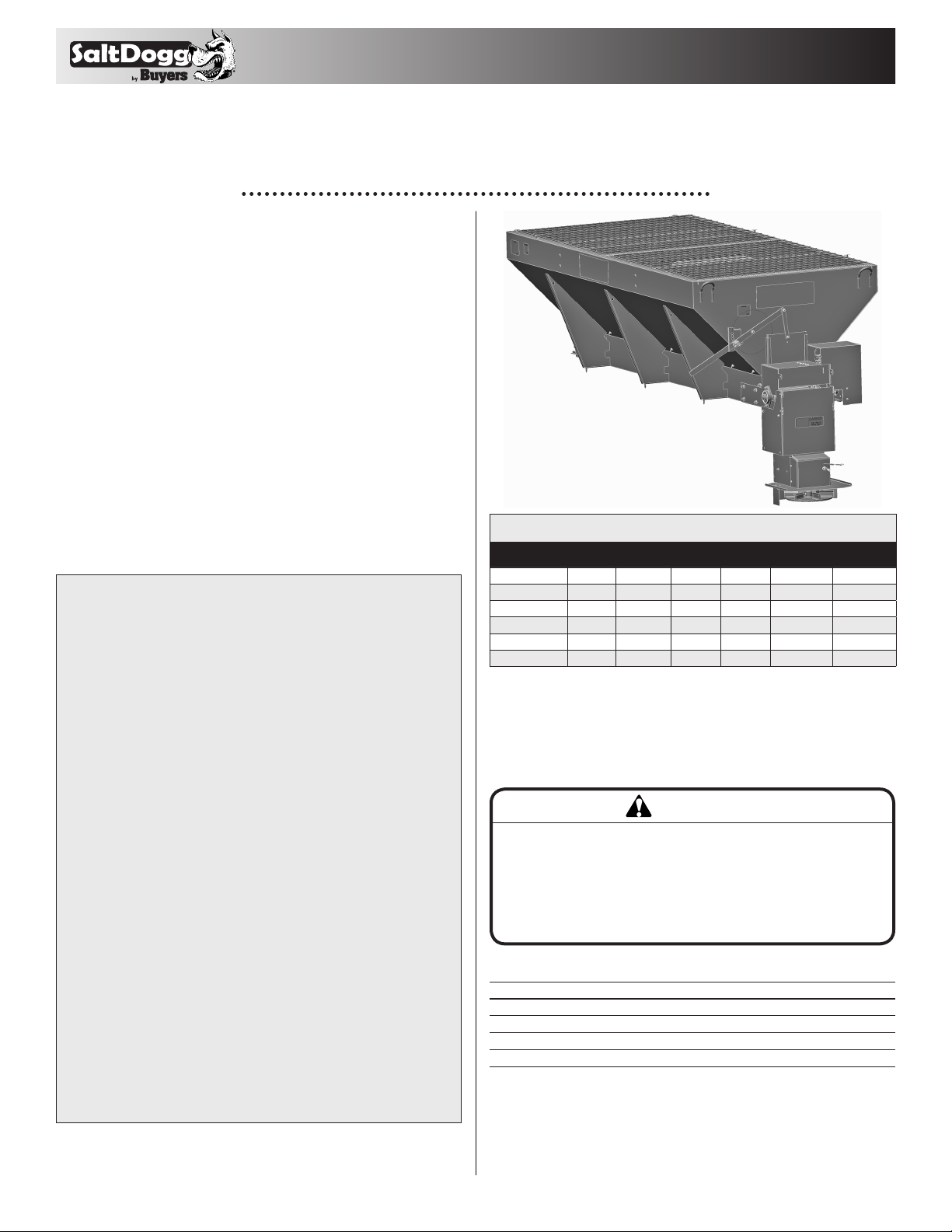
Spreader Models and Specifications
MODEL # POWER
1400455SSE
1400455SSH
1400460SSE
1400460SSH
1400465SSE
1400465SSH
Electric 96" 116.5" 58" 1,335 lbs. 2.5 yds.
Hydraulic 96" 118 . 8" 58" 1,335 lbs. 2.5 yds.
Electric 108" 128.5" 58" 1,4 00 lbs. 2.75 yds.
Hydraulic 108" 130 " 58" 1,4 0 0 lbs . 2.75 yds.
Electric 118 " 13 2" 58" 1,4 66 lbs. 3.0 yds.
Hydraulic 118" 132" 58" 1,4 6 6 lbs . 3.0 yds.
HOPPER
LENGTH
OVERALL
LENGTH
OVERALL
WIDTH
EMPTY
WEIGHT CAPAC ITY
General Information
1. Recommended Vehicle Requirements:
This spreader is to be used on trucks with dump bodies or flat
bed trucks with a Gross Vehicle Weight Rated chassis of 15,000
lbs. or greater.
CAUTION
Do not overload vehicle beyond the vehicle’s Gross
Vehicle Weight Rating (GVWR) or Gross Axle Weight
Ratings (GAWR). Check the vehicle’s load rating
certification sticker for maximum vehicle capacity.
2. Average Material Weights:
MATERI AL WEIGH T (PO UNDS PER CUBI C YARD)
#1 Rock Salt 950
#2 Rock Salt 1,215
Coarse Sand - Dry 2,565
Coarse Sand - Wet 3,240
Note: To calculate the total spreader weight (including ice
control material); add the empty spreader weight plus the
ice control material and spreader accessories.
1
3. Recommended Fastener Torques:
Maintain all fastener torques as shown in the following table.
Failure to do so may cause injury to persons.
SAE GRADE 2
FT-LBS
1/4 -20 6 9
5/16 -18 11 18
3/8 -18 19 31
3/8-24 24 46
7/16 -14 30 50
1/2-13 45 75
9/16-12 66 110
5/ 8 -11 93 150
SAE GRADE 5
FT-LBS
Safety Precautions
WARNING
Observe the following Safety Precautions before,
during and after operating this spreader. By following
these precautions and common sense, possible injury
to persons and potential damage to this machine may
be avoided.
1. Read this entire Owner’s Manual before operating this
spreader.
2. Read all safety decals on the spreader before operating the
spreader.
3. Check to make sure all safety guards are securely mounted
into place before operating this spreader.
4. Make sure the motor cover is securely fastened to the
spreader before operating the spreader.
5. Verify that all personnel are clear of the spreader spray area
before starting or operating this spreader.
6. Keep all loose clothing, hair, jewelry and limbs clear of the
spreader before starting or operating this spreader.
7. Do not over-load your vehicle beyond payload limits. If there
are any questions, contact the vehicle manufacturer.
8. Do not adjust, clean, oil or unclog material jams without first
turning off the spreader.
9. Do not climb on or in the spreader during operation. Do not
ride on the spreader while the vehicle is in motion.
10. Make sure the spreader is securely fastened to the vehicle
in accordance with this manual.
11. Do not operate a spreader that is in need of maintenance or
repairs.
12. Always disconnect the wire harness before removing or
replacing any electrical components.
Installation Instructions
1. Mounting the Spreader onto the Vehicle:
A. Remove the tailgate from the vehicle.
B. Lift the spreader by lifting loops on side of hopper.
WARNING
The lifting device must be adequately rated to lift a
payload equal to or greater than the spreader weight.
See page 1 for spreader weights. Empty spreader
before lifting.
C. Elevate the spreader off the vehicle with lumber. Place
lumber under the side gussets of the spreader. This will help
with removal of excess material that accumulates under the
spreader.
D. Center the spreader on the vehicle with the end of the
gear mount 14" to the rear of the nearest vertical obstruction
(bumper, trailer hitch, etc). Attach chute to spreader, check
for interference between the vehicle and the Spinner/Chute
Ass e mbly.
E. Bolt the spreader to the vehicle frame through the lengths
of lumber using the holes located in each of the four (4) side
gussets. Use 1/2" SAE Grade 5 hardware as required by
vehicle application.
F. In addition secure the spreader to the vehicle by attaching
the four (4) tie-down eyes located at each corner of the
spreader to the vehicle’s factory installed anchor points using
suitable tie-down devices.
• The spreader must be securely fastened to the frame of the
vehicle.
• Verify with the vehicle’s manufacturer that the factory
installed anchor points are designed for tie-down of such
load.
• Periodically check that the spreader mounting hardware is
securely tightened, retighten if necessary.
2
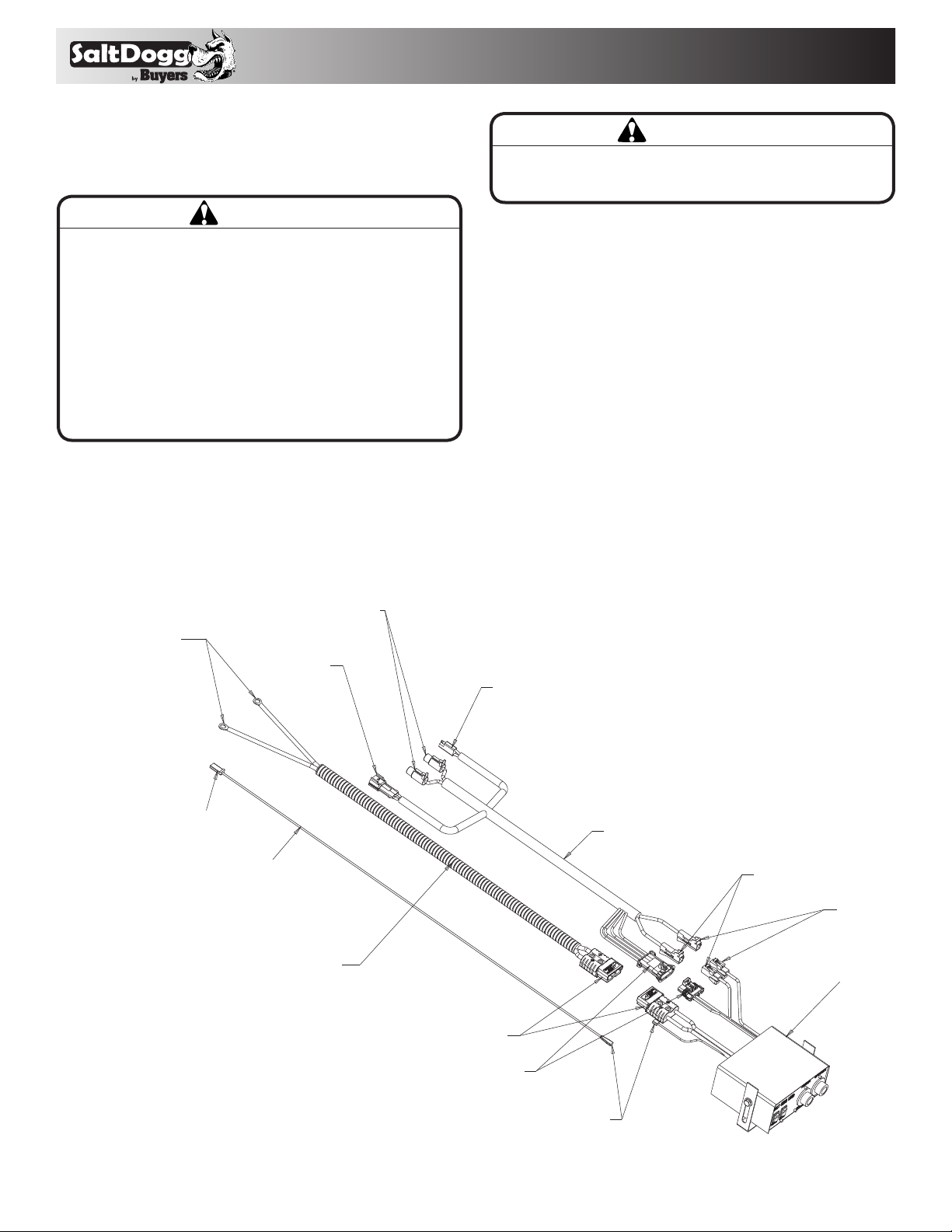
2. Control Box and Vehicle Wiring Harness Installation
Make sure you have connected the proper wire color.
This is wire ground electrical system! No connections to
truck’s frame or body allowed!
WARNING
WARNING! Do not drill holes into fuel tanks, fuel lines,
through electrical wiring, etc. that may be damaged by
drilling. To insure good performance of your spreader,
check the condition of truck’s electrical system. Using
digital voltmeter, check alternator and battery voltage.
With engine running and head lights and heater fan ON
good voltage reading should fall between 13.0 and 15.3
volts. If voltage reading falls out of this range, check and
adjust your electric system.
NOTE: Always disconnect battery before attempting to
install electrical components on your vehicle.
A. Mount the controller in a convenient location in the truck
cab. It is recommended not to mount the controller directly in
front of heat vents. Allow ample air space around controller.
B. Route both wire harnesses into truck cab through firewall
CAUTION
DO NOT MOUNT CONTROLLER IN THE WAY OF AIR
BAG DEPLOYMENT!
(it maybe necessary to drill holes). Insulate hole to avoid water
leaks.
C. Insure no wires are nicked or damaged during installation.
D. Connect the 4-pin connector on the wire harness to the
control box 4-pin connector.
E. Connect the 2-pin connector on the power cable to the .....
control box mating connector.
F. Connect wire harness single connectors to control box
connectors.
G. Connect fuse connector to the fuse terminal or ignition
switch (5 AMP max).
H. Lay out a path for the power cable to the battery, use quick
ties to secure power cable.
DO NOT CONNECT TO BATTERY AT THIS TIME!
I. Lay out path for wire harness to the rear of the vehicle. It
is recommended to stay clear of the exhaust system. Excess
CONNECT TO BATTERY
TERMINALS ONLY
CONNECT TO FUSE OR WIRE
IN FUSE PANEL CONTROLLED
BY IGNITION SWITCH 5 AMP MAX
CONNECT TO CHAIN/ AUGER
GEAR MOTOR
CONNECT TO
CHUTE MOTOR
#0203700
#3016943
CONNECT TO VIBRATOR
OPTIONAL
CONNECT
#3016944
CONNECT
CONNECT
#3016934
CONTROLLER
CONNECT
3
CONNECT
heat can damage the wire harnesses. Use quick ties to secure
harness to underbody.
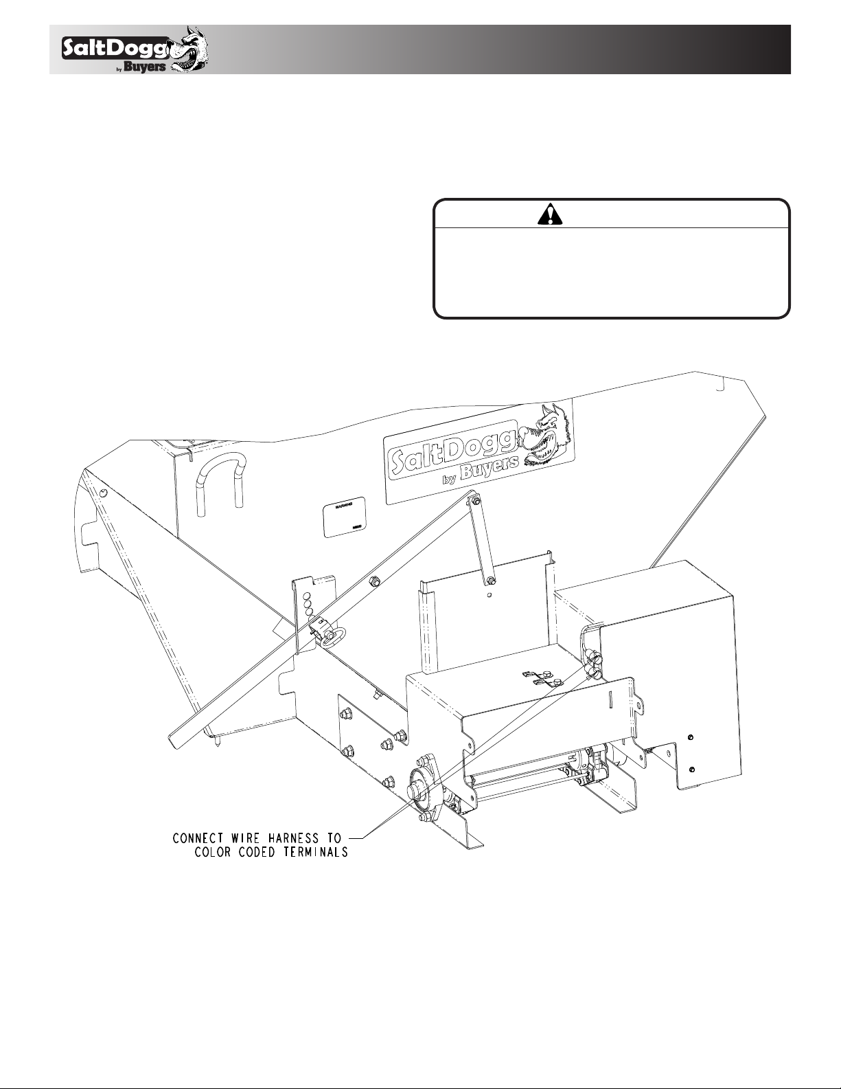
J. Connect the wire harness to the motor. Make sure wire
colors on wire harness match colors on the motor.
K. Thoroughly clean battery terminals. Make sure battery
terminals have no tarnish or corrosion. DO NOT CONNECT
WIRE HARNESS TO DAMAGED OR CORRODED
TERMINALS! IT MAY RESULT IN OVERHEATING, LOST
POWER AND POTENTIAL CONTROLLER DAMAGE!
L. Connect the power cable directly to the battery.
M. Insure all functions of the controller are
working properly.
N. Observe chain moving in proper direction. If direction is
wrong reverse wires between Motor and Wire Harness.
O. Optional spot light (5 AMP max) can be installed on
spreader. Remove cap from single white wire. Connect light to
this wire and trucks frame.
3. Spinner/Chute Assembly Operation
A. Attach chute to hopper assembly by inserting bars into holes
IMPORTAN T
Make sure all wires securely attached to vehicle or
spreader. Use wire ties and/or wire clamps to attach
wires. All excess wires must be rolled into bungles and
attached to vehicle or spreader.
4

in chute and motor mount. Then secure chute by installing
an electrical connection is made or after a connector is
disconnected.
2. Grease the following:
• Idler shaft bearings (2)
• Bearing (1)
3. Check the Feed Chain tension periodically. To check the
tension, measure in 21"-25" from the rear edge of the gear box
mount. Push up on the chain with your hand. The conveyor
chain should lift up 2"-3" off the conveyor chain guide or cross
angles.
4. Empty the spreader of all ice control material when not in use
to prevent a frozen feed chain.
hairpins. Chute heights can be adjusted by attaching lower
chute weldment to the upper one using upper or lower set of
holes.
B. The spread pattern and the amount of material dispensed is
dependant on the following factors:
1. Gear Motor RPM
2. Feed gate position
3. Shield position
4. Spinner Motor RPM
4. Precautions
A. If the feed chain does not move because of dense material or
CAUTION
Always follow the following precautions so as not to
cause damage to the spreader.
a material jam, remove all material from the hopper and free the
chain.
B. If the material in the hopper freezes, move the spreader into
a warm area to thaw.
C. To prevent the feed chain from freezing, do not store material
in the spreader.
D. The gearbox is designed to only accept torque from the
electrical motor. Therefore, DO NOT ATTEMPT TO FREE
THE FEED CHAIN BY USING A PIPE OR SIMILAR TOOL
TO MOVE OR DISLODGE THE CHAIN. If the feed chain is
moved, the gears within the gearbox will strip. This action
will void all warranties.
Spreader Maintenance
1. Use dielectric grease on all electrical connections before
Feed
Chain
21" - 25"
Rear of Sill
Extension
2" - 3"
5. Wash out the spreader when it is not in use. At the end of the
season wash out the spreader to remove all ice control materials. Thoroughly dry all metal surfaces. Paint and oil all bare
metal surfaces and chains to protect from rust. Properly store
the spreader for the next season.
Installation Instructions - Hydraulic Models
1. During assembly take precautions to keep all hydraulic com-
ponents as clean as possible.
2. Allow enough hose length to prevent kinking and stretching
of the hoses and to permit raising the dump body. Support long
hoses with wire ties or clamps.
3. Protect hoses from wear caused by sliding and/or vibration.
4. For proper rotation of conveyor chain and spinner motors,
hoses may be reversed. The spinner rotates clockwise when
looking down from the top.
Note: Use of a pipe joint sealant compatible with hydraulic
oil is recommended for all screw fittings.
5. Use swivel type hose ends to connect hoses to flow valve.
Damage to valve body may occur if the fittings in flow valve are
over tightened.
6. A 10 micron return line filter is recommended to protect the
pump, valve, and motors from wear causing contamination.
Spreader Operation - Hydraulic Models
Initial Priming and Inspecting of the System
1. Use high grade non-foaming hydraulic oil to fill reservoir
about 3/4 full.
5

2. Position valve on/off lever to off.
Hydraulic Plumbing Diagram
3/4" (1) Wire Ho se
10 Mi rco n
Filter
3/4" (1)
Wire Hose
1
T
Valve
ON/OFF Lever
Valve Key
T= Tank/Reservoir
P= Pump/Pressure In
A= Auger (Conveyer Chain)
S= Spinner
Tank
Pump
3/4" (2) Wi re Hose
A
P
S
1/2" (1) Wire Hos e
1-1/4" Spiral
Suction Hose
3/4" (2) Wi re Hose
2
1/2" (1) Wire Hos e
3/4" Quic k
Disconnects
1/2" (1) Wire Hos e
1/2" (1) Wire Hos e
1/2" Quick Disconnects
(1) Single braid wire hose
(2) Double braid wire hose
Conve yer
Chain Motor
Spinner Motor
Main Components
ITEM PART N O. QT Y. DESCRIPTION
1 HV 715 1 Dual Flow Regulator Valve
2 – 1 Reservoir 25 Gal Min
N/S H VC1 1 Dual Flow Regulator Console
3. Move auger (conveyor chain) and spinner knobs on the valve
CAUTION
• Be sure everyone is standing clear of spreader.
• Be alert for anything that may require shutting
down the system.
• Before working in or around spreader equipment,
be sure all hydraulic controls are moved to off
position.
to the open position.
4. Engage PTO and circulate hydraulic oil for several minutes to
warm up.
5. Move valve on/off lever to on.
6. Inspect hydraulic system for leaks.
7. Check conveyor chain and spinner to see if they are working
properly and rotating the correct direction. To reverse rotation,
switch the hydraulic lines at the motor.
8. Refill reservoir to 3/4 full.
9. Hydraulic system should now be ready for use.
Spreader Start-up
1. Check feed gate opening and baffle positions for desired
material flow and spread pattern. See chute section.
2. Shut off spinner and auger (conveyor chain) knobs and
position the on/off lever to on. Engage the PTO and allow the
hydraulic system to warm up.
3. After the system is warm turn the spinner and auger
(conveyor chain) knobs to the desired settings.
4. Changing the conveyor chain and spinner speeds as well as
adjusting the baffle positions will produce various spread patterns.
Miscellaneous
1. Valve setting changes may be made with truck in motion.
2. By moving on/off lever to the off position, spinner and
conveyor chain may be stopped at the same time without
changing their valve settings.
Spreader Maintenance - Hydraulic Models
1. Warm up hydraulic system before using.
2. Keep the reservoir 3/4 full with high grade non-foaming
hydraulic oil.
3. Use precautions to keep contaminants from getting in
reservoir when filling.
CAUTION
Before working in or around spreader, the valve
control lever must be in the off position. Disengage
PTO and shut off engine.
CAUTION
Position the valve on/off control lever in the off
position when the spreader is not in use or is
removed. In the event the valve on/off control lever
is left in the on position, a heat problem may occur
as the pump continues to pump oil to the hydraulic
valve. This could cause a hose to burst spraying hot
oil.
4. Quick connects are a prime source of contamination.
• Clean quick connects before connecting or disconnecting
them.
• Protect quick connects from contaminates at all times.
5. Lubricate all bearings with suitable type grease on a regular
basis. More frequent lubrication is recommended during periods
of heavy use.
6. Maintain the proper lubrication level in all gearboxes with
SAE 90 gear lubricant.
7. When not in use, keep the spreader empty to prevent freezing
of material in the hopper in extremely cold weather.
8. To extend the life of your spreader:
• Hose down and clean after each use.
• Repaint and/or oil after each season.
6

Hopper Assembly Electric Model
Bill of Materials
ITEM
1 3025240 1 HOPPER WELDMENT 10 FT 3.0 CU YD SST
1 3028138 1 HOPPER WELDMENT 9 FT 2.75 CU YD SST
1 3028151 1 HOPPER WELDMENT 8 FT 2.5 CU YD SST
2 3025241 2 CROSS MEMBER, HOPPER
3 FCB037516100SS 8 BOLT, 3/8-16 X 1 CARRIAGE SST
4 FNE038016044SS 16 NUT, NYLOCK 3/8-16 X 7/16 SST
5 300 9197 1 PAN, 10' CONVEYOR FLOOR
5 3008301 1 PAN, 9' CONVEYOR FLOOR
5 3028159 1 PAN, 8' CONVEYOR FLOOR
6 3001522 4 BOLT, CARRIAGE 1/2-13 X 1 SST
7 3001523 12 NUT, HX FLNG-I/2-I3 SST
8 3025245 1 MOTOR DECK, WELDMENT
9 3004278 8 SCREW, BTN HD SOC CAP 1/2- I3x 1 SST
10 3008872 2 WIPER BELT, HOPPER
11 FWF025063007SS 6 WASHER, FLAT 1/4 SAE SS
12 FCS025020075SS 6 SCREW, CAP 1/4-20 X 3/4 SST
13 FNE025020031SS 6 NUT, NYLON INSERT 1/4-20 SST
14 3008294 2 BEARING, FLANGED
15 3006723 4 SCREW, HEX HD 1/2-13x1.5 GR5 SS
16 FNE050013053SS 4 NUT, NYLOCK 1/2-13 SS
17 3008316 1 SHAFT, SPROCKET DRIVE END
18 3008289 1 COUPLING, DRIVE SHAFT/ GEARBOX
19 141080 3 2 PIN, CLEVIS, 3/8 X 2, 1038 ST, YZN
20 FPC013000100 2 COT TER PIN, 1/8 X 1, ZINC
21 KS402 3 KEY, 1/4 X 1/4 X 2
22 3008300 4 SPROCKET, D667H CHAIN
23 30 0 9114 1 CHAIN, 10 FT. D667H CONVEYOR
23 3008860 1 CHAIN, 9 FT. D667H CONVEYOR
23 3014539 1 CHAIN, 8 FT. D667H CONVEYOR
24 3008290 2 BEARING, HEAVY DUTY TAKE-UP
25 3 008317 1 SHAF T, IDLER SPROCKET
26 14105 0WSS 2 BOLT, WELDED TAKE UP, SCH IDLER
PART N O. OT Y. DESCRIPTION
ITEM
27 FNH063011054SS 2 NUT, HH 5/8-11 X 17/32 HIGH SST
28 300919 9 1 SHIELD, 10' TROUGH PS SIDE
28 3008353 1 SHIELD, 9' TROUGH PS SIDE
28 3014540 1 SHIELD, 8' TROUGH PS SIDE
29 3024546 1 SHIELD, 10' TROUGH DR SIDE
29 3024539 1 SHIELD, 9' TROUGH DR SIDE
29 3024535 1 SHIELD, 8' TROUGH DR SIDE
30 3014960 14 BOLT, 3/8-16 X 1 CARRIAGE SHORT NECK SST
31 3001255 14 NUT, HEX FLNG-3/8-16 SST
32 3025252 2 BAR, INVERTED VEE
33 3025254 1 INVERTED VEE, WELDMENT 10 FT
33 3028141 1 INVERTED VEE, WELDMENT 9FT
33 3028160 1 INVERTED VEE, WELDMENT 8FT
34 FCS038016100SS 12 SCREW, HHC 3/8-16 X 1 304 SST
35 3 0118 32 1 LEVER, WELDED, FEED GATE
36 3003874 1 NUT, HEX REVERSIBLE LOCK 1/2-13 SST
37 3008339 1 BAR, FEED GATE DOOR
38 3008338 1 DOOR, SALT GATE
39 1499020 1 LABEL, WARNING 1
40 1499035 2 LABEL, WARNING 3
41 1499 03 0 1 L ABEL, CAUTION 1 (PAYLOAD)
42 14990 45 1 LABEL, WARNING 4
43 3025436 2 TOP SCREEN HALF, 10FT
43 3028143 2 TOP SCREEN HALF, 9FT
43 3028154 2 TOP SCREEN HALF, 8FT
44 HP9 4 PIN, HAIR COTTER, .09 ZINC
45 3 011132 3 DECAL, SALTDOGG, BLK /WHT ON CLR 18X6.3125
46 3024575 1 GEAR MOTOR CONVEYOR 12 VDC
47 3017121 2 BRACKET, RECEPTACLE SZ8 DEUTSCH
48 FCS038016075SS 2 SCREW, HHC-3/8-16 X 3/4 SST
49 3026364 1 HOOD, GEAR MOTOR
50 301587 3 4 SCREW HI 2-I4X.74 SS SELF DRIL HEX WASHER HD
PART N O. OT Y. DESCRIPTION
7

Hopper Assembly Hydraulic Model
Bill of Materials
ITEM
1 3025240 1 HOPPER WELDMENT 10 FT 3.0 CU YD SST
1 3028138 1 HOPPER WELDMENT 9 F T 2.75 CU YD SST
1 3028151 1 HOPPER WELDMENT 8 FT 2.5 CU YD SST
2 3025241 2 CROSS MEMBER, HOPPER
3 FCB037516100SS 8 BOLT, 3/8-16 X 1 CARRIAGE SST
4 FNE038016044SS 16 NUT, NYLOCK 3/8-16 X 7/16 SST
5 3009197 1 PAN, 10' CONVEYOR FLOOR
5 3008301 1 PAN, 9' CONVEYOR FLOOR
5 3028159 1 PAN, 8' CONVEYOR FLOOR
6 300152 2 4 BOLT, CARRIAGE 1/2-13 X 1 SST
7 300152 3 12 NUT, HX FLNG-I/2-I3 SST
8 3025245 1 MOTOR DECK, WELDMENT
9 3004278 8 SCREW, BTN HD SOC CAP l/M3x 1 SST
10 3008872 2 WIPER BELT, HOPPER
11 FWF025063007SS 6 WASHER, FLAT 1/4 SAE SS
12 FCS025020075SS 8 SCREW, CAP 1/4-20 X 3/4 SST
13 FNE025020031SS 7 NUT, NYLON INSERT 1/4-20 SST
14 3008294 2 BEARING, FLANGED
15 3008 316 1 SHALT, SPROCKET DRIVE END
16 3006723 4 SCREW, HEX HD 1/2-13x1.5 GR5 SS
17 FNE050013053SS 4 NUT, NYLOCK 1/2-13 SS
18 3008289 1 COUPLING, DRIVE SHALT/ GEARBOX
19 1410803 2 PIN, CLEVIS, 3/8 X 2, 1038 ST, YZN
20 FPC013000100 2 COTTER PIN, 1/8 X 1, /INC
21 KS402 3 KEY, 1/4 X 1/4 X 2
22 3008300 4 SPROCKET, D667H CHAIN
23 30 0 9114 1 CHAIN, 10 FT. D667H CONVEYOR
23 3008860 1 CHAIN, 9 FT. D667H CONVEYOR
23 3014539 1 CHAIN, 8 FT. D667H CONVEYOR
24 3008290 2 BEARING, HEAVY DUTY TAKE-UP
25 30 08317 1 SHAFT, IDLER SPROCKET
26 141050 W SS 2 BOLT, WELDED TAKE UP, SCH IDLER
27 FNH063011054SS 2 NUT, HH 5/8-11 X 17/32 HIGH SST
PART N O.
OT Y.
DESCRIPTION
ITEM
PART N O.
OT Y.
DESCRIPTION
28 3009199 1 SHIELD, 10' TROUGH PS SIDE
28 3008353 1 SHIELD, 9' TROUGH PS SIDE
28 301454 0 1 SHIELD, 8' TROUGH PS SIDE
29 3024546 1 SHIELD, 10' TROUGH DR SIDE
29 3024539 1 SHIELD, 9' TROUGH DR SIDE
29 3024535 1 SHIELD, 8' TROUGH DR SIDE
30 301496 0 14 BOLT, 3/8-16 X 1 CARRIAGE SHORT NECK SST
31 3001255 14 NUT, HEX FLNG-3/8-16 SST
32 3025252 2 BAR, INVERTED VEE
33 3025254 1 INVERTED VEE, WELDMENT 10 FT
33 3028141 1 INVERTED VEE, WELDMENT 9FT
33 3028160 1 INVERTED VEE, WELDMENT 8FT
34 FCS038016100SS 12 SCREW, HHC 3/8-16 X 1 304 SST
35 30118 32 1 LEVER, WELDED, EEED GATE
36 3003874 1 NUT, HEX REVERSIBLE LOCK 1/2-13 SST
37 3008339 1 BAR, FEED GATE DOOR
38 3008338 1 DOOR, SALT GATE
39 1499020 1 LABEL, WARNING 1
40 1499 035 2 LABEL, WARNING 3
41 1499030 1 LABEL, CAUTION 1 (PAYLOAD)
42 1499045 1 LABEL, WARNING 4
43 3025436 2 TOP SCREEN HALF, 10FT
43 30 28143 2 TOP SCREEN HALF, 9FT
43 3028154 2 TOP SCREEN HALF, 8FT
44 HP9 4 PIN, HAIR COTTER, .09 ZINC
45 3 011132 3 DECAL, SALT DOGG, BLK/WHT ON CLR 18X6.3125
46 1401200 1 GEARBOX
47 FWL050088013SS 4 WASHER, LOCK - 1/2 SPLIT SST
48 FCS050013100SS 4 SCREW, HHC-1/2-13 X 1 SST
49 3009215 1 COUPLING, SHALT 1 X 1
50 CM004P 1 MOTOR, HYD 4 BOLT
51 FWL038069009SS 4 WASHER, LOCK RHS-3/8 SST
52 3025249 1 COVER, SHAFT
8

Chute Assembly - Electric Model
Bill of Materials
ITEM
PART N O. O T Y. DESCRIPTION
1 3025428 1 UPPER CHUTE WELDMENT
2 3025432 1 LOWER CHUTE WELDMENT
3 – 4 SCREW, HHC-3/8-16 X 3/4 SST
4 – 9 NUT, NYLOCK 3/8-16 X 7/16 SST
5 3016309 1 MOTOR 12 VDC, .5 HP SPINNER
6 – 6 SCREW, HHC 3/8-16 X 1 304 SST
7 3012 393 1 SPINNER, 14" POLY CW
8 30071 13 1 PIN, CLEVIS, 5/16 X 2-1/2, . 141 HOLE ZN
9 – 1 COTTER PIN, 1/8 X 1, ZINC
10 3025430 1 SHIELD, CHUTE
11 – 3 BOLT, 3/8-16 X 1 CARRIAGE SHORT NECK SST
12 3025431 1 BAFFLE
ITEM
PART N O. O T Y. DESCRIPTION
13 3024581 1 PIN, CHUTE ADJUSTMENT
14 HP9 2 PIN, HAIR COTTER, .09 ZINC
15 3024582 1 MOTOR COVER, CHUTE
16 – 4
SCREW #12-14x,74 SS SELF DRILL HEX
WASHER HD
17 3006753 1 WIRE HARNESS, CHUTE
18 1410 241 1 WIPER BELT, HOPPER
19 – 3 WASHER, FLAT 1/4 SAE SS
20 – 3 SCREW, CAP 1/4-20 X 3/4 SST
21 – 3 NUT, NYLON INSERT 1/4-20 SST
22 9240131 1 DECAL #1, DANGER STAY CLEAR
9

Chute Assembly - Hydraulic Model
Bill of Materials
ITEM
PART N O. O T Y. DESCRIPTION
1 3025428 1 UPPER CHUTE WELDMENT
2 3025432 1 LOWER CHUTE WELDMENT
3 – 8 SCREW, HHC-3/8- 1 6 X 3/4 SST
4 – 9 NUT, NYLOCK 3/8- 1 6X7/16 SST
5 3025430 1 SHIELD, CHUTE
6 – 3 BOLT, 3/8-16 X 1 CARRIAGE SHORT NECK
7 3025431 1 BAFFLE
8 – 2 SCREW, HHC 3/8- 16 X 1 304 SST
9 3024581 1 PIN, CHUTE ADJUSTMENT
10 HP9 2 PIN, HAIR COTTER, .09 ZINC
ITEM
PART N O. O T Y. DESCRIPTION
11 1410241 1 WIPER BELT, HOPPER
12 – 3 WASHER, FLAT 1 /4 SAE SS
13 – 3 SCREW, CAP 1 /4-20 X 3/4 SST
14 – 3 NUT, NYLON INSERT 1/4-20 SST
15 9240131 1 DECAL #1 , DANGER STAY CLEAR
16 CM004P 1 MOTOR, HYD 4 BOLT
17 – 4 WASHER, LOCK RHS-3/8 SST
18 30086 1 1 1 DISC, SPINNER ASSEMBLY
19 – 1 WASHER, 5/16 SAE SST
20 – 1 SCREW HH CAP 1 /4-20 X 3.0 SST
10

Spreader Kit - Electric Model
Bill of Materials
ITEM
PART N O. O T Y. DESCRIPTION
1 3024576 1 HOPPER ASM,3.0 CU YD SST ELECTRIC MOTOR
1 3028146 1 HOPPER ASM,2.75 CU YD SST ELECTRIC MOTOR
1 3028148 1 HOPPER ASM,2.5 CU YD SST ELECTRIC MOTOR
2 3025440 1 CHUTE ADJUSTABLE ELECTRIC,SST
3 3026058 1 HARDWARE BOX,1400465SSE
11

Spreader Kit - Hydraulic Model
Bill of Materials
ITEM
PART N O. OT Y. DESCRIPTION
1 3024576 1 HOPPER ASM,3.0 CU YD SST HYDRAULIC MOTOR
1 3028137 1 HOPPER ASM,2.75 CU YD SST HYDRAULIC MOTOR
1 3028149 1 HOPPER ASM,2.5 CU YD SST HYDR AULIC MOTOR
3026061 1 CHUTE ADJUSTABLE HYDRAULIC,SST
2
3026062 1 HARDWARE BOX,1400465SSH
3
12
3026059 Rev B
 Loading...