

Mail Chests – 4350
Pedestal Mounted Installation Instructions
Installing Mail Chest on a Pedestal
Thank you for selecting Salsbury’s 4350 mail chest mailbox.
This instruction sheet is for installing the 4350 mail chest on a
pedestal. Other installation instructions are available for installing the
mail chest on spreaders, mounting a newspaper holder, and
mounting the pedestal in a concrete footing.
When you install a curbside or roadside mailbox, make sure that it is
easily accessible to the mail carrier. By regulation a locked mailbox
should be 41” to 45” from the ground or street surface up to the point
of mail entry. The door should be set back 6” to 8” back from the
front face of the curb or the road edge. However, you should check
with your local postmaster to ensure that the mailbox is installed
according to local regulations. It is important to note that it is not the
responsibility of mail carriers to open mailboxes that are locked,
accept keys for this purpose, or lock mailboxes after delivery of the
mail.
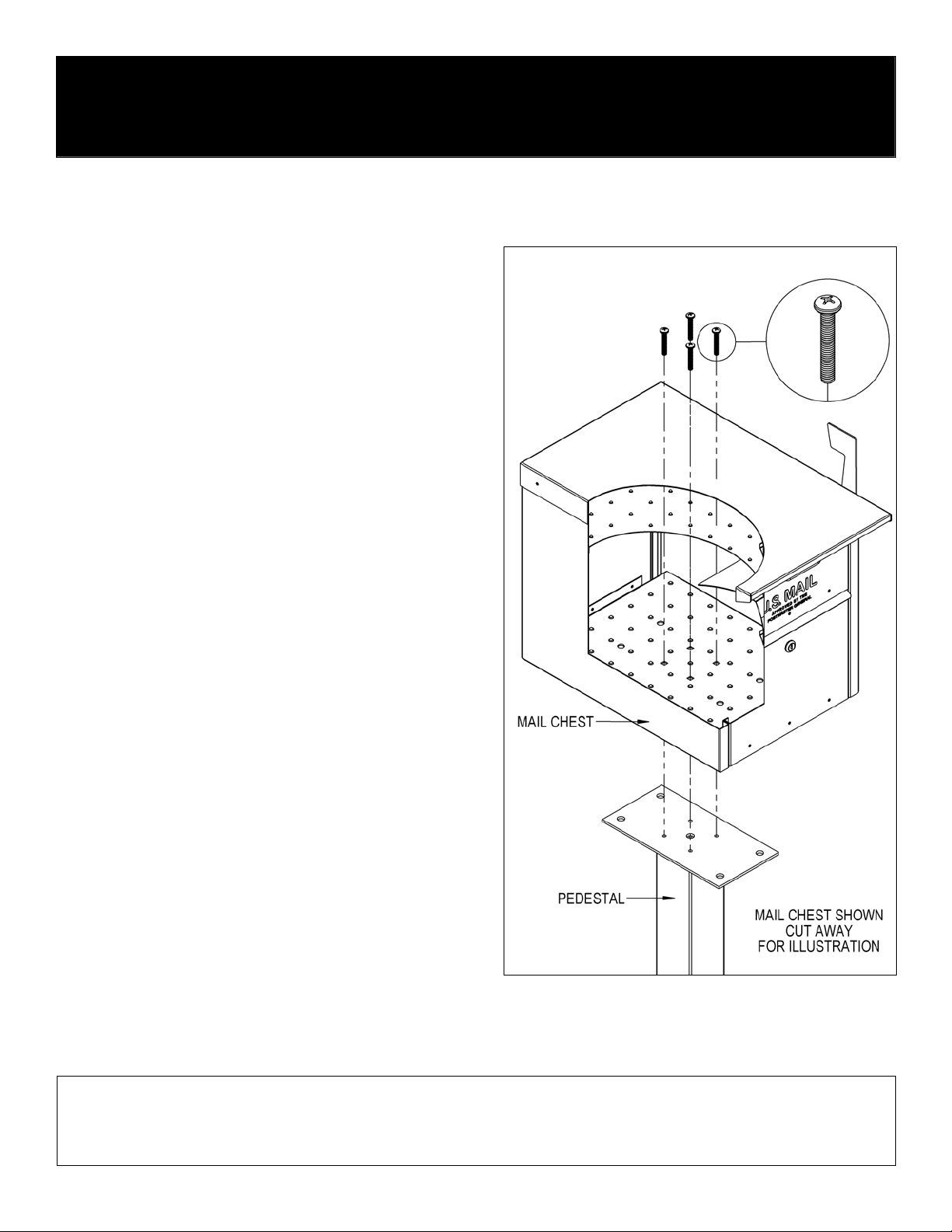
All hardware to install the mail chest is provided with the pedestal.
To install the mail chest, unlock and open the front or rear door of the
mail chest and install four (4) 5/16” - 18 x 2” long pan head bolts
through the four (4) square holes in the inside floor of the mail chest
and through the four (4) tapped holes on the top plate of the
pedestal. Installation is now complete.
Additional hardware provided is not needed and may be discarded.
U.S.P.S. APPROVED
SALSBURY INDUSTRIES
1010 East 62nd Street, Los Angeles, CA 90001-1598
Phone: 1-800-624-5269 Int’l Phone: 323-846-6700
Fax: 1-800-624-5299 Int’l Fax: 323-846-6800
www.mailboxes.com engineering
Installation instructions are provided as general guidelines. It is advised that a professional installer be consulted. Salsbury Industries assumes no product assembly or installation liability.
Copyright © 2011 Salsbury Industries. All rights reserved. (Rev. 01, 11/1/11)
@mailboxes.com
Mail Chest – 4350
Wall or Column Mounted Installation Instructions
Installing Mail Chest in a Wall or Column
Thank you for selecting Salsbury’s 4350 mail chest mailbox.
This instruction sheet is for installing the 4350 mail chest in a hole in
a wall or column. Other installation instructions are available for
installing the mail chest on a pedestal, installing the mail chest on a
deluxe post, installing the mail chest on spreaders, mounting a
newspaper holder, and mounting a pedestal in a concrete footing.
When you install a curbside or roadside mailbox, make sure that it is
easily accessible to the mail carrier. By regulation a locked mailbox
should be 41” to 45” from the ground or street surface up to the point
of mail entry. The door should be set back 6” to 8” back from the
front face of the curb or the road edge. However, you should check
with your local postmaster to ensure that the mailbox is installed
according to local regulations. It is important to note that it is not the
responsibility of mail carriers to open mailboxes that are locked,
accept keys for this purpose, or lock mailboxes after delivery of the
mail.
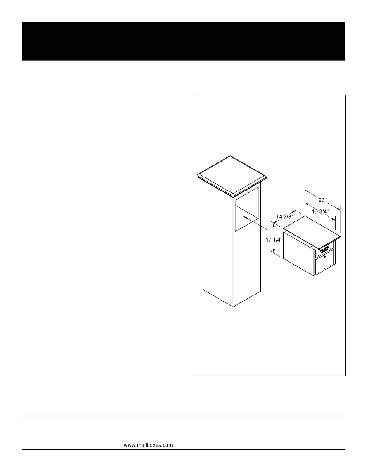
It is recommended to have the unit present before starting the wall or
column construction to obtain the best possible installation. The
rough opening should be sized approximately 1/2” larger than the
outside dimensions of the unit.
Due to construction variations and method of fastening the unit in the
installation, the fastening hardware is not included. Choose
fasteners that are appropriate for the construction method. Note:
remove flag from mail chest before installing into column or wall.
U.S.P.S. APPROVED
SALSBURY INDUSTRIES
1010 East 62nd Street, Los Angeles, CA 90001-1598
Phone: 1-800-624-5269 Int’l Phone: 323-846-6700
Fax: 1-800-624-5299 Int’l Fax: 323-846-6800
www.mailboxes.com engineering
Installation instructions are provided as general guidelines. It is advised that a professional installer be consulted. Salsbury Industries assumes no product assembly or installation liability.
Copyright © 2011 Salsbury Industries. All rights reserved. (Rev. 01, 11/1/11)
@mailboxes.com
Mail Chests – 4350
Newspaper Holder on Pedestal Installation Instructions
U.S.P.S. APPROVED
Thank you for selecting Salsbury’s 4350 mail chest mai lbox. This instruction sheet is for installing the 4350 mail c hest along with a 4315 newspaper holder on a
pedestal. Other installation instructions are av ailable for installing the mail chest on a pedestal, or on a deluxe post, installing the mail chest on spreaders , and
installing the pedestal in a concrete footing.
When you install a curbside or roadside mailbox, make sure that it is easily accessible to the mail carrier. By regulation a locked mailbox should be 41” to 45” from
the ground or street surface up to the point of mail entry. The door should be set back 6” to 8” back from the front face of the curb or the road edge. However, you
should check with your local postmaster to ensure that the mailbox is installed according to local regulations. It is important to note that it is not the responsibility of
mail carriers to open mailboxes that are locked, accept keys for this purpose, or lock mailboxes after delivery of the mail.
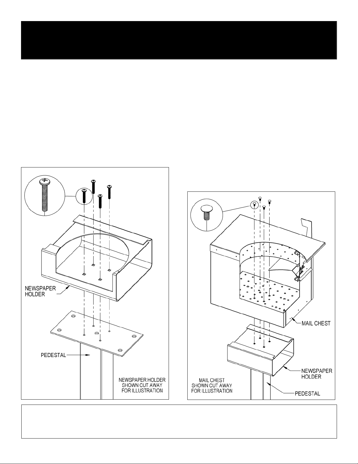
Newspaper Holder to Pedestal Installation
Install four (4) 5/16”-18 x 2” long pan head bolts provided with the pedestal
through the four (4) square holes shown in the inside floor of the news paper
holder and through the four (4) tapped holes on th e top plate of the pedes tal.
Insert a Phillips head screw driver through each squ are hole directly above,
and in the top of the newspaper holder, to tighten the pan head bolts.
Mail Chest Installation on a Newspaper Holder and Pedestal
All hardware to attach the mail chest to the newspap er holder is included with
the newspaper holder. To attach the mail chest to the newspaper holder,
unlock and open the front door or rear door of the mail chest and insta ll four
(4) 5/16”-18 X 3/4” long carriage bol ts into (4) square holes in the floor of th e
mail chest and through the four (4) square holes shown on the top of the
newspaper holder. Install 5/16” flat washers and 5/16” -18 hex nuts on the
ends of the four (4) bolts protruding below the top of the newspaper holder.
Cover the hex nuts with cap plugs. Installation is complete. Additional
hardware provided is not needed and may be discarded.
SALSBURY INDUSTRIES
1010 East 62nd Street, Los Angeles, CA 90001-1598
Phone: 1-800-624-5269 Int’l Phone: 323-846-6700
Fax: 1-800-624-5299 Int’l Fax: 323-846-6800
www.mailboxes.com engineering
Installation instructions are provided as general guidelines. It is advised that a professional installer be consulted. Salsbury Industries assumes no product assembly or installation liability.
Copyright © 2011 Salsbury Industries. All rights reserved. (Rev. 01, 11/1/11)
@mailboxes.com

Mail Chests – 4350
Spreader & Pedestal Installation Instructions
U.S.P.S. APPROVED
Thank you for selecting Salsbury’s 4350 mail chest mailbox. This instruction sheet is for instal ling the 4350 mail chest on spreaders and a pedestal. Other
installation instructions are available for instal li ng the m ail chest on a ped estal, or on a de lux e post, ins tallin g t he mail chest on a newspaper holder, and install ing the
pedestal in a concrete footing.
When you install a curbside or roadside mailbox, make sure that it is easily acc essible to the mail carrier. By regul ation a lock ed mailbox should be 41” to 45” from
the ground or street surface up to the point of mail entry. T he door should be set back 6” to 8” back from the front face of t he curb or the road edge. However, you
should check with your local postmaster to ensur e that the mailbox is installed acc ording to local regul ations. It is imp ortant to note that it is not the responsibi lity of
mail carriers to open mailboxes that are locked, accept keys for this purpose, or lock mailboxes after delivery of the mail.
Installing Mail Chests on a Spreader & Pedestal
4382 2-Wide Spreader
All hardware to attach the spreader to the pedestal is included with the
spreader. To attach the spreader to the pedestal, inst all four (4) 5/16”-18 X
1” long hex flange head bolts through the four (4) center square h oles of the
spreader and through the four (4) tapped holes on the top plate of the
standard mailbox post. Cover the hex flange head bolts with cap plugs.
All hardware to attach the mail chests to the spr eader is included with the
spreader. To attach a mail chest, open the front door or rear door of the mail
chest and install four (4) 5/16”-18 x 1-3/4” long carriage bolts through the four
(4) square holes in the inside floor of the mail chest, through the square
spacer, and through the four (4) correspondin g square holes in top of the
spreader. Install 5/16” flat washers and 5/16”-18 hex nuts on the ends of the
four (4) bolts protruding below the bottom of t he spreader. Repeat these
steps for the other mail chest. Installation is now complete. Additional
hardware provided is not needed and may be discarded.
4383 3-Wide Spreader
All hardware to attach the spreader to the pedestal is included with the
pedestal. To attach the spreader to the pedestal requires simultaneously
attaching the center mail chest to the spreader and to the pe destal. Start by
opening the front door or rear door of the center mail chest and install four
(4) 5/16”-18 X 2” long pan head bolts through t he four (4) square holes in th e
inside floor of the center mail chest, through the squa re spacer, through the
four (4) center square holes of the s preader, and through the four (4) t apped
holes on the top plate of the pedestal.
All hardware to attach the remaining two mail chests to the spreader is
included with the spreader. To attach an additional mail chest, open the front
door or rear door of the mail chest and install fo ur (4) 5/16”-18 x 1-3/4” lon g
carriage bolts through the four (4) squar e holes in the ins ide floor of the mai l
chest, through the square spacer, and through the four corresponding square
holes in top of the spreader. Install 5/16” flat was hers and 5/16” -18 hex nuts
on the ends of the four (4) bolts protruding below the bottom of th e spreader.
Repeat these steps for the other mail chest. Installation is now complete.
SALSBURY INDUSTRIES
1010 East 62nd Street, Los Angeles, CA 90001-1598
Phone: 1-800-624-5269 Int’l Phone: 323-846-6700
Fax: 1-800-624-5299 Int’l Fax: 323-846-6800
www.mailboxes.com engineering
Installation instructions are provided as general guidelines. It is advised that a professional installer be consulted. Salsbury Industries assumes no product assembly or installation liability.
Copyright © 2011 Salsbury Industries. All rights reserved. (Rev. 01, 11/1/11)
@mailboxes.com

Mail Chests – 4350
2-Wide Spreader with Newspaper Holders
on a Pedestal Installation Instructions
Installing Mail Chests on 2-Wide Spreader with
Newspaper Holders on a Pedestal
Thank you for selecting Salsbury’s 4350 mail chest mailbox.
This instruction sheet is for installing 4350 ma il chests on 2-wide spreaders
with 4315 newspaper holders and a pedestal. A different ins truction she et is
available for installing 4350 mail chests on a 3-wide spreader with 4315
newspaper holders and a pedestal. Other installation instructions are
available for installing the mail chest on a pedestal, or on a deluxe post,
installing the mail chest on a spreader, and installing the pedestal in a
concrete footing.
When you install a curbside or roadside mailbox , make sure that it is easily
accessible to the mail carrier. By regulation a locked mailbox shoul d be 41”
to 45” from the ground or street sur face up to the point of mail entry. The
door should be set back 6” to 8” back from the front face of the curb or the
road edge. However, you should check with your l ocal postm aster to ens ure
that the mailbox is installed accordin g to local regulations. It is i mportant to
note that it is not the responsibility of mail carriers to open ma ilbox es that are
locked, accept keys for this purpose, or lock mailboxes after delivery of the
mail.
Spreader Installation to Pedestal
All hardware to attach the spreader to the pedestal is included with the
spreader. To attach the spreader to the pedestal, inst all four (4) 5/16”-18 X
1” long hex flange head bolts through the four (4) center square h oles of the
spreader and through the four (4) tapped holes on the top plate of the
pedestal. Cover the hex flange head bolts with cap plugs.
U.S.P.S. APPROVED
Newspaper Holders Installation to Pedestal
All hardware to attach the newspaper holders to the spreader is included with
the spreader. To attach a newspaper holder to the spreader, install four (4)
5/16”-18 x 1-3/4” long carriage bolts thro ugh the four (4) square h oles in the
inside floor of the newspaper holder and through the four (4) correspon ding
holes on the spreader. Install 5/16” flat washers and 5/16”-18 hex nuts on
the ends of the four (4) bolts protruding below the b ottom of the spreader.
Repeat these steps for the other newspaper holder.
Mail Chest Installation to Newspaper Holders
All hardware to attach the mail chests to the newspaper holders is inc luded
with the newspaper holders. To attach a mail chest to a newspaper holde r,
install four (4) 5/16”-18 X 3/4” long carriage bo lts into (4) squar e holes in the
floor of the mail chest and through the four (4) square h oles on the t op of the
newspaper holder. Install 5/16” flat washers and 5/16” -18 hex nuts on the
ends of the four (4) bolts protruding below the top of the newspa per holder.
Cover the hex nuts with cap plugs. Repeat these steps for th e other mail
chest. Installation is now complete. Additional hardware provided is not
needed and may be discarded.
SALSBURY INDUSTRIES
1010 East 62nd Street, Los Angeles, CA 90001-1598
Phone: 1-800-624-5269 Int’l Phone: 323-846-6700
Fax: 1-800-624-5299 Int’l Fax: 323-846-6800
www.mailboxes.com engineering
Installation instructions are provided as general guidelines. It is advised that a professional installer be consulted. Salsbury Industries assumes no product assembly or installation liability.
Copyright © 2011 Salsbury Industries. All rights reserved. 11/1/11
@mailboxes.com

Mail Chests – 4350
3-Wide Spreader with Newspaper Holders
on a Pedestal Installation Instructions
Installing Mail Chests on 3-Wide Spreader with
Newspaper Holders on Pedestal
you for selecting Salsbury’s 4350 mail chest mailbox.
Thank
This instruction sheet is for installing 4350 mail chests on a 3-wide spreader
with 4315 newspaper holders and a pedestal. A different ins truction she et is
available for installing 4350 mail chests on 2-wide spreaders with 4315
newspaper holders and a pedestal. Other installation instructions are
available for installing the mail chest on a pedestal, or on a deluxe post,
installing the mail chest on a spreader, and installing the pedestal in a
concrete footing.
When you install a curbside or roadside mailbox , make sure that it is easily
accessible to the mail carrier. By regulation a locked mailbox shoul d be 41”
to 45” from the ground or street sur face up to the point of mail entry. The
door should be set back 6” to 8” back from the front face of the curb or the
road edge. However, you should check with your l ocal postm aster to ens ure
that the mailbox is installed accordin g to local regulations. It is i mportant to
note that it is not the responsibility of mail carriers to open ma ilbox es that are
locked, accept keys for this purpose, or lock mailboxes after delivery of the
.
mail
Spreader and Newspaper Holders Installation to
Pedestal
Attaching the spreader to the pedestal requ ires simultaneously attaching the
center newspaper holder to the spreader and to the pedestal. Start by
installing four (4) 5/16”-18 x 2” long pan head bolts provided with the
pedestal through the four (4) square holes in the inside flo or of the center
newspaper holder, through the four (4) center square holes in top of the
spreader, and through the four (4) tapped holes on the top plate of the
pedestal. Insert a Phillips head screw driver through each square hole
directly above, and in the top of the newspaper holder, to ti ghten the pan
head bolts.
All hardware to attach the remaining two newspaper holders to the spreader
is included with the spreader. To attach an additional newspaper holder,
install four (4) 5/16”-18 x 1-3/4” long carriage bolts through the four (4)
square holes in the inside floor of the newspaper hold er and throug h the four
(4) corresponding square holes in top of the spreader. Install 5/16” flat
washers and 5/16”-18 hex nuts on the ends of the f our (4) bolts protruding
below the bottom of the spreader. Repeat these steps for the remaining
newspaper holder.
U.S.P.S. APPROVED
Mail Chest Installation to Newspaper Holders
All hardware to attach the mail chests to the newspaper holders is inc luded
with the newspaper holders. To attach a mail chest to a newspaper holde r,
install four (4) 5/16”-18 X 3/4” long carriage bo lts into (4) squar e holes in the
floor of the mail chest and through the four (4) square h oles on the t op of the
newspaper holder. Install 5/16” flat washers and 5/16” -18 hex nuts on the
ends of the four (4) bolts protruding below the top of the newspa per holder.
Cover the hex nuts with cap plugs. Repeat these steps for th e other mail
chests. Installation is now complete. Additional hardware prov ided is not
needed and may be discarded.
SALSBURY INDUSTRIES
1010 East 62nd Street, Los Angeles, CA 90001-1598
Phone: 1-800-624-5269 Int’l Phone: 323-846-6700
Fax: 1-800-624-5299 Int’l Fax: 323-846-6800
www.mailboxes.com engineering
Installation instructions are provided as general guidelines. It is advised that a professional installer be consulted. Salsbury Industries assumes no product assembly or installation liability.
Copyright © 2011 Salsbury Industries. All rights reserved. 11/1/11
@mailboxes.com

Mail Chests – 4350
In-Ground Mounted Pedestal Installation Instructions
Installing the In-Ground Mounted Pedestal or Post
When you install a curbside or roadside mailbox, make sure that it is
easily accessible to the mail carrier. By regulation a locked mailbox
should be 41” to 45” from the ground or street surface up to the point
of mail entry. The door should be set back 6” to 8” back from the
front face of the curb or the road edge. However, you should check
with your local postmaster to ensure that the mailbox is installed
according to local regulations. It is important to note that it is not the
responsibility of mail carriers to open mailboxes that are locked,
accept keys for this purpose, or lock mailboxes after delivery of the
mail.
To install the in-ground mounted pedestal, begin by digging a hole for
the concrete footing and then prepare the concrete. The top surface
of the footing should be about 12” by 18”. See the illustration for the
relative position of the rectangular footing to the pedestal and
mailbox. The concrete should extend into the ground 24” or greater if
your local frost line is deeper. Installing the concrete below the frost
line will prevent movement during ground freezing and thawing. The
bottom of the hole for the concrete footing should be filled with a
depth of about 6” of gravel to promote drainage under the post. The
top of the footing should be sloped for water runoff.
When digging the hole for the footing, be careful to not puncture
water, sewer, or gas lines.
After digging the hole, set the pedestal in the hole and fill the hole
with the prepared concrete mix. Prod the mix with a stick while filling
to reduce any air pockets. If you want to conceal the concrete, pour
it to within a few inches of the top of the hole and cover with soil after
the concrete has set. Use a carpenter’s level on the sides of the
pedestal to ensure that the pedestal is aligned vertically. Periodically
check the vertical alignment of the pedestal as the concrete is curing.
U.S.P.S. APPROVED
SALSBURY INDUSTRIES
1010 East 62nd Street, Los Angeles, CA 90001-1598
Phone: 1-800-624-5269 Int’l Phone: 323-846-6700
Fax: 1-800-624-5299 Int’l Fax: 323-846-6800
www.mailboxes.com engineering
Installation instructions are provided as general guidelines. It is advised that a professional installer be consulted. Salsbury Industries assumes no product assembly or installation liability.
Copyright © 2011 Salsbury Industries. All rights reserved. (Rev. 01, 11/1/11)
@mailboxes.com

Mail Chests – 4350
Bolt Mounted Pedestal Installation Instructions
Installing the Bolt Mounted Pedestal
When you install a curbside or roadside mailbox, make sure that it is
easily accessible to the mail carrier. By regulation a locked mailbox
should be 41” to 45” from the ground or street surface up to the point
of mail entry. The door should be set back 6” to 8” back from the
front face of the curb or the road edge. However, you should check
with your local postmaster to ensure that the mailbox is installed
according to local regulations. It is important to note that it is not the
responsibility of mail carriers to open mailboxes that are locked,
accept keys for this purpose, or lock mailboxes after delivery of the
mail.
To install the bolt mounted pedestal, begin by digging a hole for the
concrete footing and then prepare the concrete. The top surface of
the footing should be about 12” by 18”. See the illustration for the
relative position of the rectangular footing to the pedestal and
mailbox. The concrete should extend into the ground 24” or greater if
your local frost line is deeper. Installing the concrete below the frost
line will prevent movement during ground freezing and thawing. The
bottom of the hole for the concrete footing should be filled with a
depth of about 6” of gravel to promote drainage under the post. The
top of the footing should be sloped for water runoff.
When digging the hole for the footing, be careful to not puncture
water, sewer, or gas lines.
Hardware for attaching the pedestal to the concrete footing is not
included. J-bolts are shown in the illustration as an example. The
concrete footing should include reinforcing steel and four (4) 1/2”
anchor studs protruding at least 1” above the concrete surface.
Place the anchor studs in a 4” x 10” pattern in the concrete to align
with the holes in the pedestal base.
When the concrete has cured sufficiently, install four (4) leveling nuts
on the anchor studs. Set the pedestal on the leveling nuts with the
four (4) anchor studs protruding through the holes in the pedestal
base plate. Adjust the leveling nuts to square up the pedestal.
Install four (4) nuts and washers on the anchor studs and tighten
securely.
U.S.P.S. APPROVED
CONCRETE
ANCHORS
NOT
INCLUDED
SALSBURY INDUSTRIES
1010 East 62nd Street, Los Angeles, CA 90001-1598
Phone: 1-800-624-5269 Int’l Phone: 323-846-6700
Fax: 1-800-624-5299 Int’l Fax: 323-846-6800
www.mailboxes.com engineering
Installation instructions are provided as general guidelines. It is advised that a professional installer be consulted. Salsbury Industries assumes no product assembly or installation liability.
Copyright © 2011 Salsbury Industries. All rights reserved. (Rev. 04, 11/1/11)
@mailboxes.com
 Loading...