

Roadside Mailboxes – 4325
Pedestal Mounted Installation Instructions
Installing Mailbox on a Pedestal
Thank you for selecting Salsbury’s 4325 roadside mailbox.
This instruction sheet is for installing the 4325 mailbox on a pedestal.
Other installation instructions are available for installing the mailbox
on a deluxe mailbox post, installing the mailbox on spreaders,
mounting a newspaper holder, and mounting the pedestal in a
concrete footing.
When you install a curbside or roadside mailbox, make sure that it is
easily accessible to the mail carrier. By regulation a locked mailbox
should be 41” to 45” from the ground or street surface up to the point
of mail entry. The door should be set back 6” to 8” back from the
front face of the curb or the road edge. However, you should check
with your local postmaster to ensure that the mailbox is installed
according to local regulations. It is important to note that it is not the
responsibility of mail carriers to open mailboxes that are locked,
accept keys for this purpose, or lock mailboxes after delivery of the
mail.
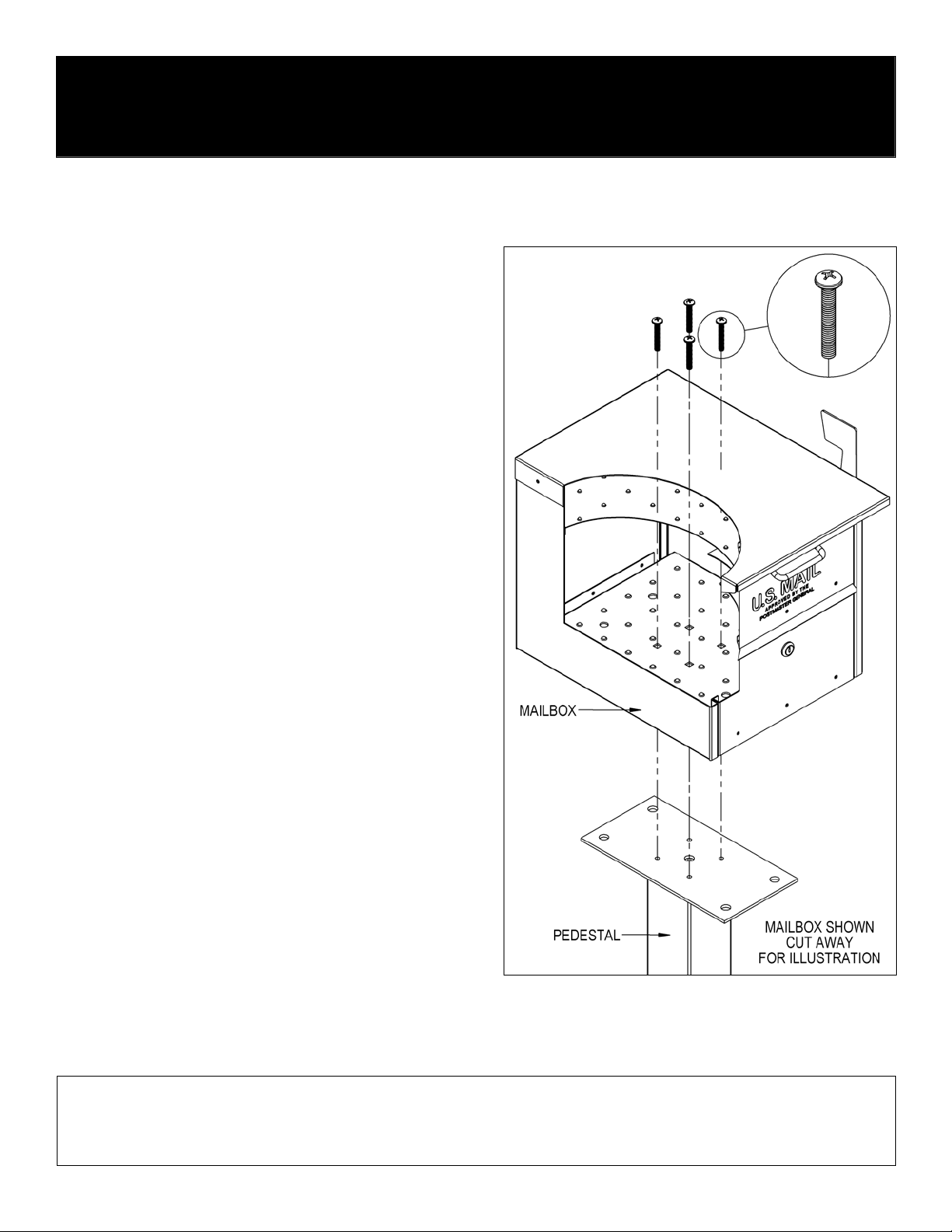
All hardware to install the mailbox is provided with the pedestal. To
install the mailbox, unlock and open the front or rear door of the
mailbox and install four (4) 5/16” - 18 x 2” long pan head bolts
through the four (4) square holes in the inside floor of the mailbox
and through the four (4) tapped holes on the top plate of the
pedestal. Installation is now complete.
Additional hardware provided is not needed and may be discarded.
U.S.P.S. APPROVED
SALSBURY INDUSTRIES
1010 East 62nd Street, Los Angeles, CA 90001-1598
Phone: 1-800-624-5269 Int’l Phone: 323-846-6700
Fax: 1-800-624-5299 Int’l Fax: 323-846-6800
www.mailboxes.com engineering
Installation instructions are provided as general guidelines. It is advised that a professional installer be consulted. Salsbury Industries assumes no product assembly or installation liability.
Copyright © 2011 Salsbury Industries. All rights reserved. (Rev. 01, 11/1/11)
@mailboxes.com
SALSBURY INDUSTRIES
1010 East 62nd Street, Los Angeles, CA 90001-1598
Phone: 1-800-624-5269 Int’l Phone: 323-846-6700
Fax: 1-800-624-5299 Int’l Fax: 323-846-6800
www.mailboxes.com engineering@mailboxes.com
Roadside Mailboxes – 4325
Wall or Column Mounted Installation Instructions
Installing Mailbox in a Wall or Column
Thank you for selecting Salsbury’s 4325 roadside mailbox.
This instruction sheet is for installing the 4325 mailbox in a hole in a
wall or column. Other installation instructions are available for
installing the mailbox on a pedestal, installing the mailbox on a
deluxe mailbox post, installing the mailbox on spreaders, mounting a
newspaper holder, and mounting a pedestal in a concrete footing.
When you install a curbside or roadside mailbox, make sure that it is
easily accessible to the mail carrier. By regulation a locked mailbox
should be 41” to 45” from the ground or street surface up to the point
of mail entry. The door should be set back 6” to 8” back from the
front face of the curb or the road edge. However, you should check
with your local postmaster to ensure that the mailbox is installed
according to local regulations. It is important to note that it is not the
responsibility of mail carriers to open mailboxes that are locked,
accept keys for this purpose, or lock mailboxes after delivery of the
mail.
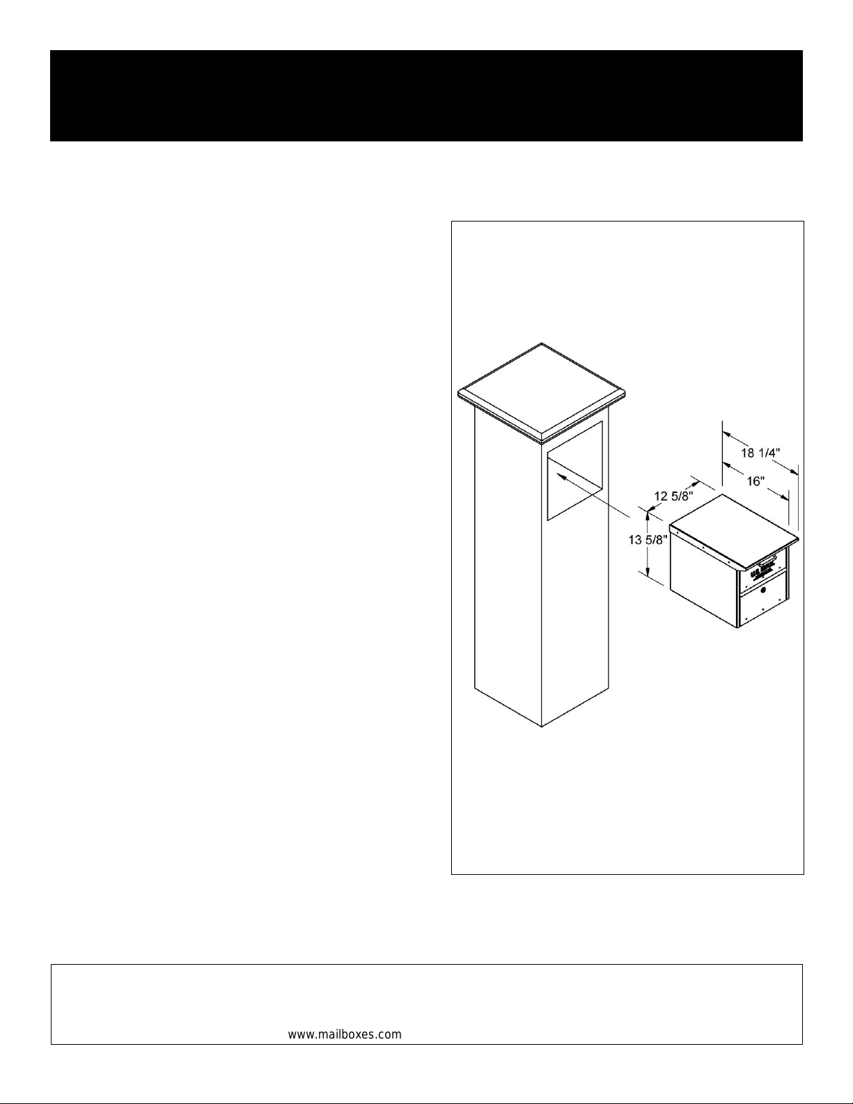
It is recommended to have the unit present before starting the wall or
column construction to obtain the best possible installation. The
rough opening should be sized approximately 1/2” larger than the
outside dimensions of the unit. Note: remove flag from mailbox
before installing into column or wall.
Due to construction variations and method of fastening the unit in the
installation, the fastening hardware is not included. Choose
fasteners that are appropriate for the construction method.
U.S.P.S. APPROVED
Installation instructions are provided as general guidelines. It is advised that a professional installer be consulted. Salsbury Industries assumes no product assembly or installation liability.
Copyright © 2011 Salsbury Industries. All rights reserved. (Rev. 01, 11/1/11)
Roadside Mailboxes – 4325
Newspaper Holder on Pedestal Installation Instructions
U.S.P.S. APPROVED
Thank you for selecting Salsbury’s 4325 roa dside mailbox. This instruction sheet is for installing the 4325 mailbox alon g with a 4315 newspaper holder on a
pedestal. Other installation instructions are availabl e for installing the mailbox on a pe destal, or on a deluxe mailbox post, installing the mailbox on s preaders, and
installing the pedestal in a concrete footing.
When you install a curbside or roadside mailbox, make sure that it is easily accessible to the mail carrier. By regulation a locked mailbox should be 41” to 45” from
the ground or street surface up to the point of mail entry. The door should be set back 6” to 8” back from the front face of the curb or the road edge. However, you
should check with your local postmaster to ensure that the mailbox is installed according to local regulations. It is important to note that it is not the responsibility of
mail carriers to open mailboxes that are locked, accept keys for this purpose, or lock mailboxes after delivery of the mail.
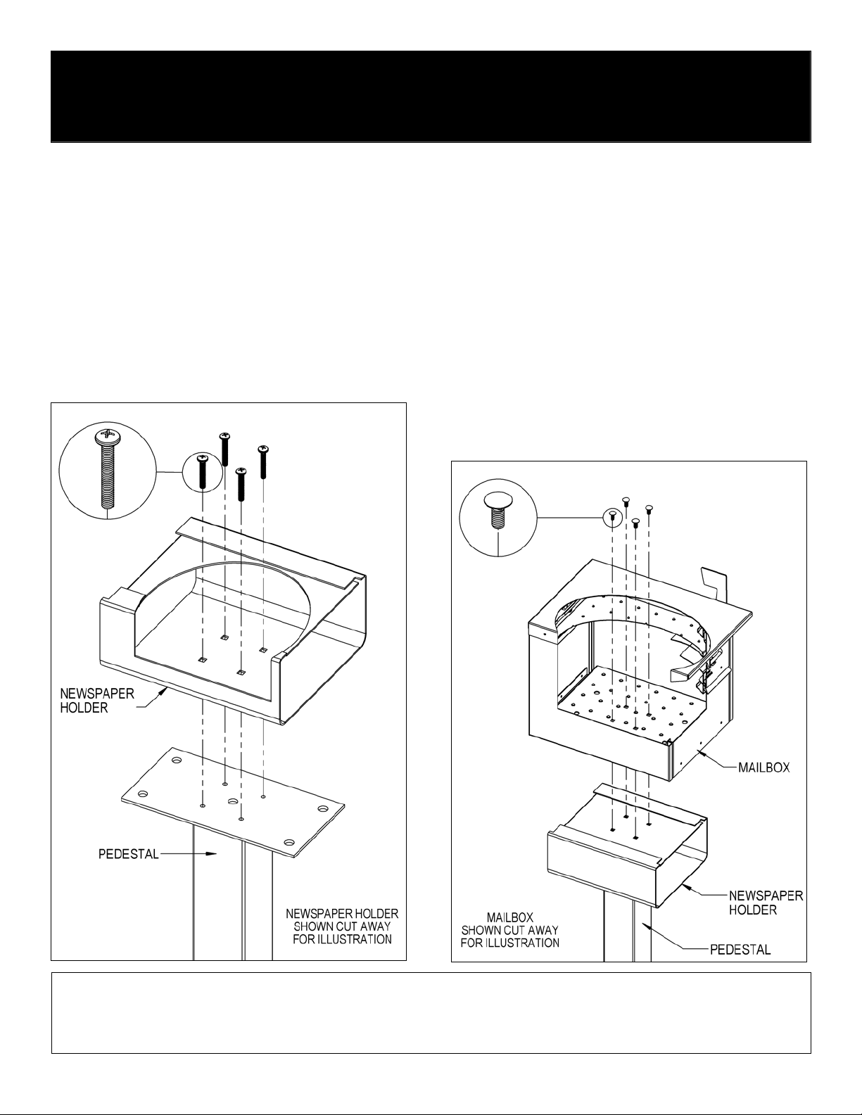
Newspaper Holder to Pedestal Installation
Install four (4) 5/16”-18 x 2” long pan head bolts provided with the pedestal
through the four (4) square holes shown in the inside floor of the news paper
holder and through the four (4) tapped holes o n the top plate of the pedes tal.
Insert a Phillips head screw driver through each s quare hole directly above,
and in the top of the newspaper holder, to tighten the pan head bolts.
Mailbox Installation on a Newspaper Holder and Pedestal
All hardware to attach the mailbox to the newspaper holder is includ ed with
the newspaper holder. To attach the mailbox to the n ew spaper hold er, unloc k
and open the front door or rear door of the mailbox and ins tall four (4) 5/16”18 X 3/4” long carriage bolts into (4) square holes in t he floor of the mailbox
and through the four (4) square holes shown on the top of th e newspaper
holder. Install 5/16” flat washers and 5/ 16”-18 hex nuts on the ends of the
four (4) bolts protruding below the top of the newspaper holder. Cover the
hex nuts with cap plugs. Installation is complete. Additional hardware
provided is not needed and may be discarded.
SALSBURY INDUSTRIES
1010 East 62nd Street, Los Angeles, CA 90001-1598
Phone: 1-800-624-5269 Int’l Phone: 323-846-6700
Fax: 1-800-624-5299 Int’l Fax: 323-846-6800
www.mailboxes.com engineering
Installation instructions are provided as general guidelines. It is advised that a professional installer be consulted. Salsbury Industries assumes no product assembly or installation liability.
Copyright © 2011 Salsbury Industries. All rights reserved. (Rev. 01, 11/1/11)
@mailboxes.com
SALSBURY INDUSTRIES
1010 East 62nd Street, Los Angeles, CA 90001-1598
Phone: 1-800-624-5269 Int’l Phone: 323-846-6700
Fax: 1-800-624-5299 Int’l Fax: 323-846-6800
www.mailboxes.com engineering@mailboxes.com
Roadside Mailboxes – 4325
Deluxe Mailbox Post Installation Instructions
U.S.P.S. APPROVED
Thank you for selecting Salsbury Industries 4325 roadside mailbox. This instruction sheet is for installing the 4325 mailbox on a Salsbury deluxe mailbox post. Other
installation instructions are available for installing the mailbox on a pedestal, installing the mailbox on spreaders, mounting a newspaper holder, and mounting the
pedestal in a concrete footing.
When you install a curbside or roadside mailbox, make sure that it is easily accessible to the mail carrier. By regulation a locked mailbox should be 41” to 45” from
the ground or street surface up to the point of mail entry. The door should be set back 6” to 8” back from the front face of the curb or the road edge. However, you
should check with your local postmaster to ensure that the mailbox is installed according to local regulations. It is important to note that it is not the responsibility of
mail carriers to open mailboxes that are locked, accept keys for this purpose, or lock mailboxes after delivery of the mail.
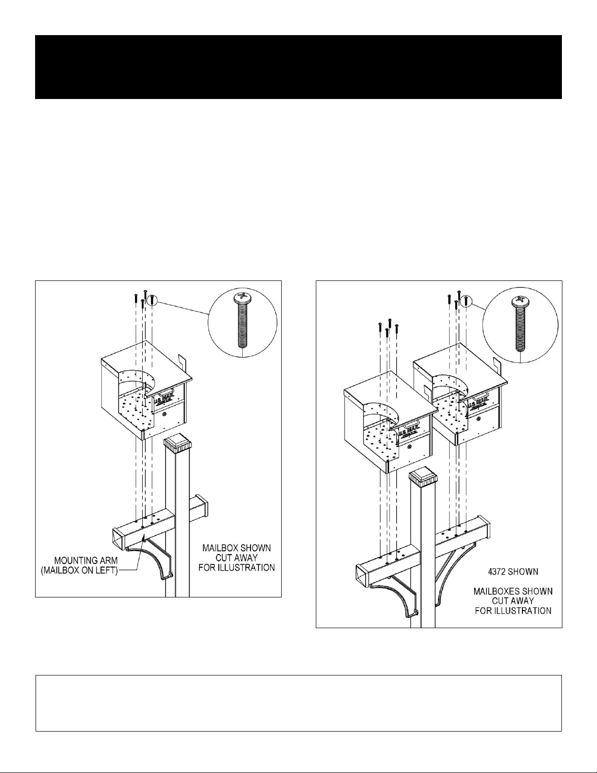
All hardware required to assemble the mailbox(es) to the deluxe mailbox post is provided with the post. Each mailbox requires four (4) 5/16”-18 x 2” long pan head
bolts to attach to the post arm(s). To install the mailbox, unlock and open the front door or rear door of the mailbox and install the four (4) 5/16”-18 x 2” long pan
head bolts through the four (4) square holes in the inside floor of the mailbox and into the four (4) tapped holes in the arm of the deluxe mailbox post. Additional
hardware provided is not needed and may be discarded.
4370 Deluxe Mailbox Post
4372, 4373, 4374 Deluxe Mailbox Post
Note: On the 4370 deluxe mailbox post, the longer mounting arm which
accommodates the mailbox can be on either the left or right side. When
attaching the post to the ground, position the post so the longer mounting
arm is on the side desired. Then mount the mailbox on the mounting arm
with the mailbox facing the street or roadway.
The 4373 deluxe mailbox post accommodates three mailboxes. The 4374
deluxe mailbox post accommodates four mailboxes.
Installation instructions are provided as general guidelines. It is advised that a professional installer be consulted. Salsbury Industries assumes no product assembly or installation liability.
Copyright © 2013 Salsbury Industries. All rights reserved. (Rev. 01, 5/21/13)

Roadside Mailboxes – 4325
Deluxe Newspaper Holders on Deluxe Mailbox Post
Installation Instructions
Installing Newspaper Holders on Deluxe Mailbox
Posts
Thank you for selecting Salsbury’s 4325 roadside mailbox.
This instruction sheet is for install ing the 4325 mailbox along with a 4315
newspaper holder on a deluxe mailbox post. Other ins tallation instructions
are available for installing the mailbox on a pedestal , or on a deluxe mailbox
post, installing the mailbox on spreaders, and installing the pedestal in a
concrete footing.
When you install a curbside or roadside mailb ox, make sure that it is easily
accessible to the mail carrier. By regulation a locked mailbox sho uld be 41”
to 45” from the ground or street sur face up to the point of mail entry. The
door should be set back 6” to 8” back from the front face of the curb or the
road edge. However, you should check with your loc al postmas ter to ens ure
that the mailbox is installed accordi ng to local regulations. It is important to
note that it is not the responsibility of mail carriers to open ma ilbox es that are
locked, accept keys for this purpose, or lock mailboxes after delivery of the
mail.
Newspaper Holder Installation to Deluxe Post
Installation of newspaper holders to each deluxe p ost, 4870 one-sided, or
4872, is the same. Attach one newspaper holder to the 4870 one-s ided
post. Attach one additional newspaper holder to the 4872 two-si ded post.
All hardware required to assemble the newspaper holders(s) to the deluxe
mailbox post is provided with the post. To a ttach a newspaper h older to the
post, install four (4) 5/16”-18 x 2” long pan head bolts through the four (4)
square holes shown in the inside fl oor of the newspaper holder and through
the four (4) tapped holes in the arm of the deluxe mailbox post. Repeat
these steps for the other newspaper holder(s).
U.S.P.S. APPROVED
Mailbox Installation to Newspaper Holders
Installation of the mailbox to the newspaper holder on each deluxe post,
4870 one-sided, or 4872 two-sided, is the same. Attach one mail box to the
4870 one-sided post. Attach one addit ional mailbox to the 4872 two-sided
post. All hardware to attach the mailbox(es) to t he newspaper holder(s) is
included with the newspaper holder(s). To attach a mailbox to a news paper
holder, open the front door or rear door of the mailbox and install four (4)
5/16”-18 X 3/4” long carriage bolts into (4) square hol es in the floor of the
mailbox and through the four (4) square holes shown on the top of the
newspaper holder. Install 5/16” flat washers and 5/1 6”-18 hex nuts on the
ends of the four (4) bolts protruding below the top of the newspaper h older.
Cover the hex nuts with cap plugs. Repeat these steps for the other
mailbox(es). Installation is now complete. Additi onal hardware provided is
not needed and may be discarded.
Note: On the 4370 deluxe mailbox post, the longer mounting arm which
accommodates the newspaper holder and m ailbox can be on either the left
or right side. When attaching the post to the ground, position the post s o the
longer mounting arm is on the side desired. T hen mount the newspaper
holder and mailbox on the mountin g arm wi th the mail box facin g the s tr eet or
roadway.
SALSBURY INDUSTRIES
1010 East 62nd Street, Los Angeles, CA 90001-1598
Phone: 1-800-624-5269 Int’l Phone: 323-846-6700
Fax: 1-800-624-5299 Int’l Fax: 323-846-6800
www.mailboxes.com engineering
Installation instructions are provided as general guidelines. It is advised that a professional installer be consulted. Salsbury Industries assumes no product assembly or installation liability.
Copyright © 2011 Salsbury Industries. All rights reserved. 11/1/11
@mailboxes.com

SALSBURY INDUSTRIES
1010 East 62nd Street, Los Angeles, CA 90001-1598
Phone: 1-800-624-5269 Int’l Phone: 323-846-6700
Fax: 1-800-624-5299 Int’l Fax: 323-846-6800
www.mailboxes.com engineering@mailboxes.com
Roadside Mailboxes – 4325
2-Wide and 3-Wide Spreader & Pedestal Installation Instructions
U.S.P.S. APPROVED
Thank you for selecting Salsbury’s 4325 roadside mailbox. This instruction sheet is for installing 4325 mailboxes on a 2-wide or 3-wide spreader and a pedestal. A
different instruction sheet is available for installing 4325 mailboxes on a 4-wide spreader and a pedestal. Other installation instructions are available for installing the
mailbox on a pedestal, or on a deluxe mailbox post, installing the mailbox on a newspaper holder, and installing the pedestal in a concrete footing.
When you install a curbside or roadside mailbox, make sure that it is easily accessible to the mail carrier. By regulation a locked mailbox should be 41” to 45” from
the ground or street surface up to the point of mail entry. The door should be set back 6” to 8” back from the front face of the curb or the road edge. However, you
should check with your local postmaster to ensure that the mailbox is installed according to local regulations. It is important to note that it is not the responsibility of
mail carriers to open mailboxes that are locked, accept keys for this purpose, or lock mailboxes after delivery of the mail.
Installing Mailboxes on Spreader & Pedestal
4382 2-Wide Spreader
All hardware to attach the spreader to the pedestal is included with the
spreader. To attach the spreader to the pedestal, install four (4) 5/16”-18 X
1” long hex flange head bolts through the four (4) center square holes of the
spreader and through the four (4) tapped holes on the top plate of the
standard mailbox post. Cover the hex flange head bolts with cap plugs.
All hardware to attach the mailboxes to the spreader is included with the
spreader. To attach a mailbox, open the front door or rear door of the
mailbox and install four (4) 5/16”-18 x 1-3/4” long carriage bolts through the
four (4) square holes in the inside floor of the mailbox, through the square
spacer, and through the four (4) corresponding square holes in top of the
spreader. Install 5/16” flat washers and 5/16”-18 hex nuts on the ends of the
four (4) bolts protruding below the bottom of the spreader. Repeat these
steps for the other mailbox. Installation is now complete. Additional
hardware provided is not needed and may be discarded.
4383 3-Wide Spreader
All hardware to attach the spreader to the pedestal is included with the
pedestal. To attach the spreader to the pedestal requires simultaneously
attaching the center mailbox to the spreader and to the pedestal. Start by
opening the front door or rear door of the center mailbox and install four (4)
5/16”-18 X 2” long pan head bolts through the four (4) square holes in the
inside floor of the center mailbox, through the square spacer, through the
four (4) center square holes of the spreader, and through the four (4) tapped
holes on the top plate of the pedestal.
All hardware to attach the remaining two mailboxes to the spreader is
included with the spreader. To attach an additional mailbox, open the front
door or rear door of the mailbox and install four (4) 5/16”-18 x 1-3/4” long
carriage bolts through the four (4) square holes in the inside floor of the
mailbox, through the square spacer, and through the four corresponding
square holes in top of the spreader. Install 5/16” flat washers and 5/16”-18
hex nuts on the ends of the four (4) bolts protruding below the bottom of the
spreader. Repeat these steps for the other mailbox. Installation is now
complete.
Installation instructions are provided as general guidelines. It is advised that a professional installer be consulted. Salsbury Industries assumes no product assembly or installation liability.
Copyright © 2014 Salsbury Industries. All rights reserved. (Rev. 02, 2/19/14)

SALSBURY INDUSTRIES
1010 East 62nd Street, Los Angeles, CA 90001-1598
Phone: 1-800-624-5269 Int’l Phone: 323-846-6700
Fax: 1-800-624-5299 Int’l Fax: 323-846-6800
www.mailboxes.com engineering@mailboxes.com
Roadside Mailboxes – 4325
4-Wide Spreader & Pedestal Installation Instructions
U.S.P.S. APPROVED
Thank you for selecting Salsbury’s 4325 roadside mailbox. This instruction sheet is for installing 4325 mailboxes on a 4-wide spreader and a pedestal. A different
instruction sheet is available for installing 4325 mailboxes on a 2-wide or 3-wide spreader and a pedestal. Other installation instructions are available for installing
the mailbox on a pedestal, or on a deluxe mailbox post, installing the mailbox on a newspaper holder, and installing the pedestal in a concrete footing.
When you install a curbside or roadside mailbox, make sure that it is easily accessible to the mail carrier. By regulation a locked mailbox should be 41” to 45” from
the ground or street surface up to the point of mail entry. The door should be set back 6” to 8” back from the front face of the curb or the road edge. However, you
should check with your local postmaster to ensure that the mailbox is installed according to local regulations. It is important to note that it is not the responsibility of
mail carriers to open mailboxes that are locked, accept keys for this purpose, or lock mailboxes after delivery of the mail.
Installing Mailboxes on Spreader & Pedestal
4384 4-Wide Spreader
All hardware to attach the spreader to the pedestal is included with the pedestal. To attach the spreader to the pedestal, install four (4) 5/16”-18 X 1” long hex flange
head bolts through the four (4) center square holes of the spreader and through the four (4) tapped holes on the top plate of the pedestal. Cover the hex flange head
bolts with cap plugs.
Next install a support arm by installing four (4) 5/16”-18 x 1-3/4” long carriage bolts through the four (4) square holes shown in the spreader and through the four (4)
corresponding square holes in the top plate of a support arm (supplied with spreader). Install 5/16” flat washers and 5/16”-18 hex nuts on the ends of the four (4)
bolts protruding below the bottom of the support arm. Complete the installation of the support arm by drilling a 3/16” diameter hole though each hole in the vertical
plate of the support arm and through the pedestal. Install 1/4” flat washers and 1/4” x 1” long lag screws into the post. Cover the lag screws with cap plugs. Repeat
these steps for the other support arm.
All hardware to attach the mailboxes to the spreader is included with the spreader. To attach a mailbox, open the front door or rear door of the mailbox and install
four (4) 5/16”-18 x 1-3/4” long carriage bolts through the four (4) square holes in the inside floor of the mailbox, through the 1” tall square spacer, and through the four
(4) corresponding square holes in top of the spreader. Install 5/16” flat washers and 5/16”-18 hex nuts on the ends of the four (4) bolts protruding below the bottom of
the spreader. Repeat these steps for the other mailboxes. Installation is now complete. Additional hardware provided is not needed and may be discarded.
Installation instructions are provided as general guidelines. It is advised that a professional installer be consulted. Salsbury Industries assumes no product assembly or installation liability.
Copyright © 2014 Salsbury Industries. All rights reserved. 2/19/14

SALSBURY INDUSTRIES
1010 East 62nd Street, Los Angeles, CA 90001-1598
Phone: 1-800-624-5269 Int’l Phone: 323-846-6700
Fax: 1-800-624-5299 Int’l Fax: 323-846-6800
www.mailboxes.com engineering@mailboxes.com
Roadside Mailboxes – 4325
2-Wide Spreader with Newspaper Holders
on a Pedestal Installation Instructions
Installing Mailboxes on 2-Wide Spreader with
Newspaper Holders on a Pedestal
Thank you for selecting Salsbury’s 4325 roadside mailbox.
This instruction sheet is for installing 4325 mailboxes on a 2-wide spreader
with 4315 newspaper holders and a pedestal. A different instruction sheet is
available for installing 4325 mailboxes on a 3-wide or 4-wide spreader with
4315 newspaper holders and a pedestal. Other installation instructions are
available for installing the mailbox on a pedestal, or on a deluxe mailbox
post, installing the mailbox on a spreader, and installing the pedestal in a
concrete footing.
When you install a curbside or roadside mailbox, make sure that it is easily
accessible to the mail carrier. By regulation a locked mailbox should be 41”
to 45” from the ground or street surface up to the point of mail entry. The
door should be set back 6” to 8” back from the front face of the curb or the
road edge. However, you should check with your local postmaster to ensure
that the mailbox is installed according to local regulations. It is important to
note that it is not the responsibility of mail carriers to open mailboxes that are
locked, accept keys for this purpose, or lock mailboxes after delivery of the
mail.
Spreader Installation to Pedestal
All hardware to attach the spreader to the pedestal is included with the
spreader. To attach the spreader to the pedestal, install four (4) 5/16”-18 X
1” long hex flange head bolts through the four (4) center square holes of the
spreader and through the four (4) tapped holes on the top plate of the
pedestal. Cover the hex flange head bolts with cap plugs.
U.S.P.S. APPROVED
Newspaper Holders Installation to Pedestal
All hardware to attach the newspaper holders to the spreader is included with
the spreader. To attach a newspaper holder to the spreader, install four (4)
5/16”-18 x 1-3/4” long carriage bolts through the four (4) square holes in the
inside floor of the newspaper holder and through the four (4) corresponding
holes on the spreader. Install 5/16” flat washers and 5/16”-18 hex nuts on
the ends of the four (4) bolts protruding below the bottom of the spreader.
Repeat these steps for the other newspaper holder.
Mailbox Installation to Newspaper Holders
All hardware to attach the mailboxes to the newspaper holders is included
with the newspaper holders. To attach a mailbox to a newspaper holder,
install four (4) 5/16”-18 X 3/4” long carriage bolts into (4) square holes in the
floor of the mailbox and through the four (4) square holes on the top of the
newspaper holder. Install 5/16” flat washers and 5/16”-18 hex nuts on the
ends of the four (4) bolts protruding below the top of the newspaper holder.
Cover the hex nuts with cap plugs. Repeat these steps for the other mailbox.
Installation is now complete. Additional hardware provided is not needed
and may be discarded.
Installation instructions are provided as general guidelines. It is advised that a professional installer be consulted. Salsbury Industries assumes no product assembly or installation liability.
Copyright © 2014 Salsbury Industries. All rights reserved. (Rev. 01, 2/19/14)

SALSBURY INDUSTRIES
1010 East 62nd Street, Los Angeles, CA 90001-1598
Phone: 1-800-624-5269 Int’l Phone: 323-846-6700
Fax: 1-800-624-5299 Int’l Fax: 323-846-6800
www.mailboxes.com engineering@mailboxes.com
Roadside Mailboxes – 4325
3-Wide Spreader with Newspaper Holders
on a Pedestal Installation Instructions
Installing Mailboxes on 3-Wide Spreader with
Newspaper Holders on Pedestal
Thank you for selecting Salsbury’s 4325 roadside mailbox.
This instruction sheet is for installing 4325 mailboxes on a 3-wide spreader
with 4315 newspaper holders and a pedestal. A different instruction sheet is
available for installing 4325 mailboxes on a 2-wide or 4-wide spreader with
4315 newspaper holders and a pedestal. Other installation instructions are
available for installing the mailbox on a pedestal, or on a deluxe mailbox
post, installing the mailbox on a spreader, and installing the pedestal in a
concrete footing.
When you install a curbside or roadside mailbox, make sure that it is easily
accessible to the mail carrier. By regulation a locked mailbox should be 41”
to 45” from the ground or street surface up to the point of mail entry. The
door should be set back 6” to 8” back from the front face of the curb or the
road edge. However, you should check with your local postmaster to ensure
that the mailbox is installed according to local regulations. It is important to
note that it is not the responsibility of mail carriers to open mailboxes that are
locked, accept keys for this purpose, or lock mailboxes after delivery of the
mail.
Spreader and Newspaper Holders Installation to
Pedestal
Attaching the spreader to the pedestal requires simultaneously attaching the
center newspaper holder to the spreader and to the pedestal. Start by
installing four (4) 5/16”-18 x 2” long pan head bolts provided with the
pedestal through the four (4) square holes in the inside floor of the center
newspaper holder, through the four (4) center square holes in top of the
spreader, and through the four (4) tapped holes on the top plate of the
pedestal. Insert a Phillips head screw driver through each square hole
directly above, and in the top of the newspaper holder, to tighten the pan
head bolts.
All hardware to attach the remaining two newspaper holders to the spreader
is included with the spreader. To attach an additional newspaper holder,
install four (4) 5/16”-18 x 1-3/4” long carriage bolts through the four (4)
square holes in the inside floor of the newspaper holder and through the four
(4) corresponding square holes in top of the spreader. Install 5/16” flat
washers and 5/16”-18 hex nuts on the ends of the four (4) bolts protruding
below the bottom of the spreader. Repeat these steps for the remaining
newspaper holder.
U.S.P.S. APPROVED
Mailbox Installation to Newspaper Holders
All hardware to attach the mailboxes to the newspaper holders is included
with the newspaper holders. To attach a mailbox to a newspaper holder,
install four (4) 5/16”-18 X 3/4” long carriage bolts into (4) square holes in the
floor of the mailbox and through the four (4) square holes on the top of the
newspaper holder. Install 5/16” flat washers and 5/16”-18 hex nuts on the
ends of the four (4) bolts protruding below the top of the newspaper holder.
Cover the hex nuts with cap plugs. Repeat these steps for the other
mailboxes. Installation is now complete. Additional hardware provided is not
needed and may be discarded.
Installation instructions are provided as general guidelines. It is advised that a professional installer be consulted. Salsbury Industries assumes no product assembly or installation liability.
Copyright © 2014 Salsbury Industries. All rights reserved. (Rev. 01, 2/19/14)

SALSBURY INDUSTRIES
1010 East 62nd Street, Los Angeles, CA 90001-1598
Phone: 1-800-624-5269 Int’l Phone: 323-846-6700
Fax: 1-800-624-5299 Int’l Fax: 323-846-6800
www.mailboxes.com engineering@mailboxes.com
Roadside Mailboxes – 4325
4-Wide Spreader with Newspaper Holders
on a Pedestal Installation Instructions
Installing Mailboxes on 4-Wide Spreader with Newspaper
Holders on a Pedestal
Thank you for selecting Salsbury’s 4325 roadside mailbox.
This instruction sheet is for installing 4325 mailboxes on a 4-wide spreader with 4315
newspaper holders and a pedestal. A different instruction sheet is available for
installing 4325 mailboxes on a 2-wide or 3-wide spreader with 4315 newspaper
holders and a pedestal. Other installation instructions are available for installing the
mailbox on a pedestal, or on a deluxe mailbox post, installing the mailbox on a
spreader, and installing the pedestal in a concrete footing.
When you install a curbside or roadside mailbox, make sure that it is easily accessible
to the mail carrier. By regulation a locked mailbox should be 41” to 45” from the
ground or street surface up to the point of mail entry. The door should be set back 6”
to 8” back from the front face of the curb or the road edge. However, you should
check with your local postmaster to ensure that the mailbox is installed according to
local regulations. It is important to note that it is not the responsibility of mail carriers
to open mailboxes that are locked, accept keys for this purpose, or lock mailboxes
after delivery of the mail.
Spreader Installation to Pedestal
All hardware to attach the spreader to the pedestal is included with the spreader. To
attach the spreader to the pedestal, install four (4) 5/16”-18 X 1” long hex flange head
bolts through the four (4) center square holes of the spreader and through the four (4)
tapped holes on the top plate of the pedestal. Cover the hex flange head bolts with
cap plugs.
Next install a support arm by installing four (4) 5/16”-18 x 1-3/4” long carriage bolts
through the four (4) square holes shown in the spreader and through the four (4)
corresponding square holes in the top plate of a support arm (supplied with spreader).
Install 5/16” flat washers and 5/16”-18 hex nuts on the ends of the four (4) bolts
protruding below the bottom of the support arm. Complete the installation of the
support arm by drilling a 3/16” diameter hole though each hole in the vertical plate of
the support arm and through the pedestal. Install 1/4” flat washers and 1/4” x 1” long
lag screws into the post. Cover the lag screws with cap plugs. Repeat these steps for
the other support arm.
U.S.P.S. APPROVED
Newspaper Holders Installation to Pedestal
All hardware to attach the newspaper holders to the spreader is included with the
spreader. To attach a newspaper holder to the spreader, install four (4) 5/16”-18 x 13/4” long carriage bolts through the four (4) square holes in the inside floor of the
newspaper holder, through the 1/4” tall square spacer and through the four (4)
corresponding holes on the spreader. Install 5/16” flat washers and 5/16”-18 hex nuts
on the ends of the four (4) bolts protruding below the bottom of the spreader. Repeat
these steps for the other newspaper holders.
Mailbox Installation to Newspaper Holders
All hardware to attach the mailboxes to the newspaper holders is included with the
newspaper holders. To attach a mailbox to a newspaper holder, install four (4) 5/16”-
18 X 3/4” long carriage bolts into (4) square holes in the floor of the mailbox and
through the four (4) square holes on the top of the newspaper holder. Install 5/16” flat
washers and 5/16”-18 hex nuts on the ends of the four (4) bolts protruding below the
top of the newspaper holder. Cover the hex nuts with cap plugs. Repeat these steps
for the other mailboxes. Installation is now complete. Additional hardware provided is
not needed and may be discarded.
Installation instructions are provided as general guidelines. It is advised that a professional installer be consulted. Salsbury Industries assumes no product assembly or installation liability.
Copyright © 2014 Salsbury Industries. All rights reserved. 2/19/14

SALSBURY INDUSTRIES
1010 East 62nd Street, Los Angeles, CA 90001-1598
Phone: 1-800-624-5269 Int’l Phone: 323-846-6700
Fax: 1-800-624-5299 Int’l Fax: 323-846-6800
www.mailboxes.com engineering@mailboxes.com
Roadside Mailboxes – 4325
Deluxe Mailbox Post Assembly Installation Instructions
Installing Arm(s) on Deluxe Mailbox Posts
Thank you for selecting Salsbury’s deluxe mailbox post. This instruction sheet is for assembling the 1-sided or 2-sided deluxe mailbox post. All hardware to
assemble the deluxe mailbox post is provided.
When you install a curbside or roadside mailbox, make sure that it is easily accessible to the mail carrier. By regulation a locked mailbox should be 41” to 45” from
the ground or street surface up to the point of mail entry. The door should be set back 6” to 8” back from the front face of the curb or the road edge. However, you
should check with your local postmaster to ensure that the mailbox is installed according to local regulations. It is important to note that it is not the responsibility of
mail carriers to open mailboxes that are locked, accept keys for this purpose, or lock mailboxes after delivery of the mail.
4370 – 1 Sided
First check to see that all the parts and fasteners in the carton have been
located and identified according to the illustration below. Also refer to the
illustration below to position the parts correctly.
1. Attach the small right-angle bracket to the post with the long leg on top
with two (2) 5/16”-18 x 2” long pan head bolts.
2. Attach the long square-tube arm to the small right angle bracket with two
(2) 1/4”-20 x 1/2” long flat-head socket screws.
3. Attach the large decorative arch to the post and the long arm with four (4)
5/16”- 8 x 1” long hex flange head bolts. Cover with cap plugs.
4. Attach the other small right-angle bracket with the long leg on the bottom
with two (2) 5/16”-18 x 2” long pan head bolts.
5. Attach the short square-tube arm to the small right-angle bracket with two
(2) 1/4’-20 x 1/2” long flat-head socket screws. This completes the
assembly.
4372 – 2 Sided for 2 Mailboxes
4373 – 2 Sided for 3 Mailboxes
4374 – 2 Sided for 4 Mailboxes
First check to see that all the parts and fasteners in the carton have been
located and identified according to the illustration below. Also refer to the
illustration below to position the parts correctly. The 4373 has the same
parts as the 4372, except one (1) arm is longer. The 4374 has the same
parts as the 4372, except the two (2) arms are longer.
1. Attach the small right-angle bracket to the post with the long leg on top
with two (2) 5/16”-18 x 2” long pan head bolts.
2. Attach the long square-tube arm to the small right angle bracket with two
(2) 1/4”-20 x 1/2” long flat-head socket screws.
3. Attach the large decorative arch to the post and the long square-tube arm
with four (4) 5/16”-18 x 1” long hex flange head bolts. Cover with cap plugs.
4. Repeat steps 1 through 3 above for the second arm on the other side of
the post. This completes the assembly.
4370 Assembly
4372, 4373, 4374 Assembly
Installation instructions are provided as general guidelines. It is advised that a professional installer be consulted. Salsbury Industries assumes no product assembly or installation liability.
Copyright © 2013 Salsbury Industries. All rights reserved. (Rev. 03, 2/19/141/13)

Roadside Mailboxes – 4325
In-Ground Mounted Pedestal or Post Installation Instructions
U.S.P.S. APPROVED
Installing the In-Ground Mounted Pedestal or Post
When you install a curbside or roadside mailbox, make sure that it is
easily accessible to the mail carrier. By regulation a locked mailbox
should be 41” to 45” from the ground or street surface up to the point
of mail entry. The door should be set back 6” to 8” back from the
front face of the curb or the road edge. However, you should check
with your local postmaster to ensure that the mailbox is installed
according to local regulations. It is important to note that it is not the
responsibility of mail carriers to open mailboxes that are locked,
accept keys for this purpose, or lock mailboxes after delivery of the
mail.
To install the in-ground mounted mailbox pedestal or post, begin by
digging a hole for the concrete footing and then prepare the concrete.
The top surface of the footing should be about 12” by 18”. See the
illustration for the relative position of the rectangular footing to the
pedestal or post and mailbox. The concrete should extend into the
ground 24” or greater if your local frost line is deeper. Installing the
concrete below the frost line will prevent movement during ground
freezing and thawing. The bottom of the hole for the concrete footing
should be filled with a depth of about 6” of gravel to promote
drainage under the post. The top of the footing should be sloped for
water runoff.
When digging the hole for the footing, be careful to not puncture
water, sewer, or gas lines.
After digging the hole, set the pedestal or post in the hole and fill the
hole with the prepared concrete mix. Prod the mix with a stick while
filling to reduce any air pockets. If you want to conceal the concrete,
pour it to within a few inches of the top of the hole and cover with soil
after the concrete has set. Use a carpenter’s level on the sides of
the pedestal or post to ensure that it is aligned vertically. Periodically
check the vertical alignment of the pedestal or post as the concrete is
curing.
SALSBURY INDUSTRIES
1010 East 62nd Street, Los Angeles, CA 90001-1598
Phone: 1-800-624-5269 Int’l Phone: 323-846-6700
Fax: 1-800-624-5299 Int’l Fax: 323-846-6800
www.mailboxes.com engineering
Installation instructions are provided as general guidelines. It is advised that a professional installer be consulted. Salsbury Industries assumes no product assembly or installation liability.
Copyright © 2011 Salsbury Industries. All rights reserved. (Rev. 01, 11/1/11)
@mailboxes.com

Roadside Mailboxes – 4325
Bolt Mounted Mailbox Pedestal Installation Instructions
Installing the Bolt Mounted Mailbox Pedestal
When you install a curbside or roadside mailbox, make sure that it is
easily accessible to the mail carrier. By regulation a locked mailbox
should be 41” to 45” from the ground or street surface up to the point
of mail entry. The door should be set back 6” to 8” back from the
front face of the curb or the road edge. However, you should check
with your local postmaster to ensure that the mailbox is installed
according to local regulations. It is important to note that it is not the
responsibility of mail carriers to open mailboxes that are locked,
accept keys for this purpose, or lock mailboxes after delivery of the
mail.
To install the bolt mounted mailbox pedestal, begin by digging a hole
for the concrete footing and then prepare the concrete. The top
surface of the footing should be about 12” by 18”. See the illustration
for the relative position of the rectangular footing to the pedestal and
mailbox. The concrete should extend into the ground 24” or greater if
your local frost line is deeper. Installing the concrete below the frost
line will prevent movement during ground freezing and thawing. The
bottom of the hole for the concrete footing should be filled with a
depth of about 6” of gravel to promote drainage under the post. The
top of the footing should be sloped for water runoff.
When digging the hole for the footing, be careful to not puncture
water, sewer, or gas lines.
Hardware for attaching the pedestal to the concrete footing is not
included. J-bolts are shown in the illustration as an example. The
concrete footing should include reinforcing steel and four (4) 1/2”
anchor studs protruding at least 1” above the concrete surface.
Place the anchor studs in a 4” x 10” pattern in the concrete to align
with the holes in the pedestal base.
When the concrete has cured sufficiently, install four (4) leveling nuts
on the anchor studs. Set the pedestal on the leveling nuts with the
four (4) anchor studs protruding through the holes in the pedestal
base plate. Adjust the leveling nuts to square up the pedestal.
Install four (4) nuts and washers on the anchor studs and tighten
securely.
U.S.P.S. APPROVED
CONCRETE
ANCHORS
NOT
INCLUDED
SALSBURY INDUSTRIES
1010 East 62nd Street, Los Angeles, CA 90001-1598
Phone: 1-800-624-5269 Int’l Phone: 323-846-6700
Fax: 1-800-624-5299 Int’l Fax: 323-846-6800
www.mailboxes.com engineering
Installation instructions are provided as general guidelines. It is advised that a professional installer be consulted. Salsbury Industries assumes no product assembly or installation liability.
Copyright © 2011 Salsbury Industries. All rights reserved. (Rev. 03, 11/1/11)
@mailboxes.com
 Loading...