


Heavy Duty Plastic Lockers – 40000 Series
Locker Installation Instructions
Thank you for selecting 40000 Series Heavy Duty Plastic Lockers. We are confident that the quality and construction of the lockers will prove to be a
good investment. These instructions are intended to assist you in the assembly, placement, and anchoring of your lockers. Individual job conditions
will dictate whether the lockers must be anchored to the wall, the floor, or both.
Separate parts from packaging and make sure all parts are accounted for before discarding any packaging
material. If any parts are missing, do not begin installation until you obtain the missing parts.
Lockers should be installed in a climate-controlled environment and shielded from direct sunlight. All lockers
must be either secured against a wall or installed back-to-back (for island configuration).
Make sure all floors and walls are clean and smooth. Remove loose impediments, such as protruding nails, and
other debris which could affect installation. The lockers must be square and level and floor supported or they will
not operate properly. A locker that is square may not be level, so be sure to check both.
Review your locker layout drawings and verify the number of lockers and components before beginning
installation.
Carefully lift lockers at the base when moving and positioning. Do not drag the lockers.
LOCKER BASES MUST BE SQUARE AND LEVEL, AND ANCHORED TO THE FLOOR BEFORE THE LOCKERS ARE
INSTALLED. THE LOCKERS WILL NOT OPERATE PROPERLY IF THE BASE IS NOT SQUARE AND LEVEL AND
NOT FLOOR-SUPPORTED. A LOCKER BASE THAT IS SQUARE MAY NOT BE LEVEL, SO BE SURE TO CHECK
BOTH.
FAILURE TO COMPLY WITH THESE INSTRUCTIONS MAY RESULT IN PERSONAL INJURY AND/OR PROPERTY
DAMAGE AND WILL VOID THE LOCKER WARRANTY.
Tools required: Tape measure - - - 9/32” drill bit - - - hammer drill for drilling into concrete - - - 6’ level and shims - - - power drill - - - Phillips driver
bit - - - clamps - - - 3/16” masonry drill bit (6” long minimum) - - - circular saw - - - right-angle power drill - - - chalk and string.
The following tips may be helpful: A string line along the top and bottom of the lockers may be used to help in alignment. If shims are required
after locker installation is complete, remove obstructive screws, apply the shims, then replace the screws. Avoid twisting the locker frames when
applying shims.
SALSBURY INDUSTRIES
1010 East 62nd Street, Los Angeles, CA 90001-1598
Phone: 1-800-562-5377 Int’l Phone: 323-846-6700
Fax: 1-800-562-5399 Int’l Fax: 323-846-6800
www.lockers.com engineering
Installation instructions are provided as general guidelines. It is advised that a professional installer be consulted. Salsbury Industries assumes no product assembly or installation liability.
Copyright © 2010 Salsbury Industries. All rights reserved. (Rev. 05, 1/13/2010) Page 1 of 6
@lockers.com
Heavy Duty Plastic Lockers – 40000 Series
Locker Base Installation Instructions
IMPORTANT: Make sure the base is square and level before anchoring to the floor. The base may be square but
not level, so be sure to check both. Shim under the base if necessary. This will ensure proper locker operation.
NOTE: The base front pieces are precut to length for 1-wide (12”) or 3-wide (36”) lockers, and come with slotted base side pieces. The length of the
base front pieces may be trimmed during installation by cutting to the desired length. DO NOT cut the base side pieces. The side pieces are the
correct length for 18” deep lockers.
Each set of base pieces includes a package of angle brackets to attach the base pieces to the floor, ¼” x 1-3/4” Tapcon screws to fasten the angle
bracket to the floor, and #10 x ½” sheet metal screws to attach the brackets to the base front and side pieces.
1. Plan the locker layout. Measure and mark placement lines on the floor for the locker bases. One or two lockers will require one or two 1-wide
bases. Three or more lockers in a row will require 3-wide bases and perhaps one or two 1-wide bases. As supplied, the bases are 1” wider than the
basic 12” wide locker to accommodate two (2) 1/2” thick side panels. As additional lockers and bases are arranged in a row with a side panel at one
end or both ends, some of the base front piece(s) must be trimmed by 1” or 1/2” to maintain a flush surface alignment between the end panel and the
base side piece. If side panels are not being used, further trimming of the front base pieces may be necessary
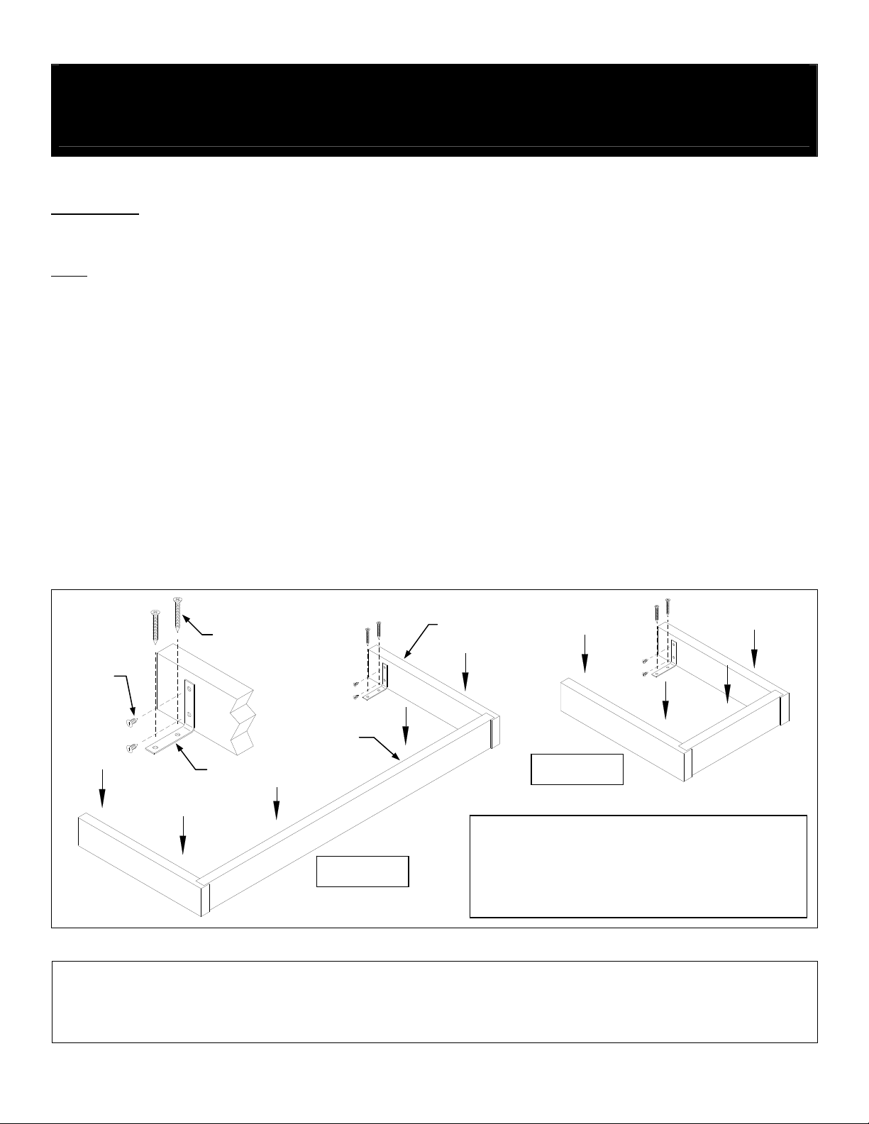
2. Position the base side and front pieces per the floor layout. The ends of the base front pieces fit into the slots in the base side pieces. See the
illustration below. Square and level the base front pieces and side pieces using shims as required. If shims are used, place them under the
mounting brackets perpendicular to the bracket.
3. Using the applicable mounting hardware supplied, anchor the base pieces to the floor. Use a 3/16” masonry drill bit for the 1/4” x 1-3/4” Tapcon
screws. Use at least two (2) angle brackets for each front piece or side piece.
Base Installation
Tapcon Screw
Side Piece
Sheet
Metal
Screws
Front Piece
Angle Bracket
1-Wide Base
Use 1/4” x 1-3/4” Tapcon concrete screws (blue) to attach
angle brackets to floor. Drill pilot hole with 3/16” masonry bit.
3-Wide Base
Use #10 x ½” sheetmetal screws to attach angle brackets to
plastic base members.
SALSBURY INDUSTRIES
1010 East 62nd Street, Los Angeles, CA 90001-1598
Phone: 1-800-562-5377 Int’l Phone: 323-846-6700
Fax: 1-800-562-5399 Int’l Fax: 323-846-6800
www.lockers.com engineering
Installation instructions are provided as general guidelines. It is advised that a professional installer be consulted. Salsbury Industries assumes no product assembly or installation liability.
Copyright © 2010 Salsbury Industries. All rights reserved. (Rev. 05, 1/13/2010) Page 2 of 6
@lockers.com

Heavy Duty Plastic Lockers – 40000 Series
Locker Installation Instructions
Note: Refer to your layouts for proper locker position. The first locker is usually installed at a corner or at the end of a run.
IMPORTANT NOTE: Make sure each locker is square and level before securing into place. The lockers may be square, but not level, so be
sure to check both. Use shims as needed.
1. Position the first locker according to your layouts. Square and level the locker using shims as required. Secure the locker to the wall in two
places with the two ¼” x 1-3/4” Tapcon screws. With the screws centered across the width of the locker, place one near the top and one near the
bottom as shown in the illustration below.
2. Postion the second locker next to the first locker. Square and level the lockers using shims as required to align the tops and fronts.
IMPORTANT: Lockers must be installed flush with adjacent lockers.
3. Temporarily clamp the lockers together at the top and bottom. Drill four (4) 9/32” clearance holes through one locker as shown in the illustration
below. The holes should be located 1-1/2” from the front of the locker and evenly spaced, top to bottom. Fasten the lockers to each other using the
#10 x ¾” security torx screws provided.
4. Position additional lockers according to your layouts. Square and level each locker using shims as required. Fasten lockers to each other using
the #10 x 3/4” security torx screws provided.
5. Secure each locker to the wall in two places with the appropriate wall installation hardware provided. Use two 1/4” x 1-3/4” Tapcon screws,
placing one near the top and one near the bottom of the locker as shown below.
CENTERLINE
DRILL 3/16” DIA. PILOT HOLE
IN CONCRETE OR BLOCK
WALL
OF LOCKER
BACK
DRILL 9/32” DIA. CLEARANCE HOLE
THROUGH BACK OF LOCKER
1/4” x 1-3/4” TAPCON SCREW
#10 x 3/4” SECURITY TORX SCREWS
SALSBURY INDUSTRIES
1010 East 62nd Street, Los Angeles, CA 90001-1598
Phone: 1-800-562-5377 Int’l Phone: 323-846-6700
Fax: 1-800-562-5399 Int’l Fax: 323-846-6800
www.lockers.com engineering
Installation instructions are provided as general guidelines. It is advised that a professional installer be consulted. Salsbury Industries assumes no product assembly or installation liability.
Copyright © 2010 Salsbury Industries. All rights reserved. (Rev. 05, 1/13/2010) Page 3 of 6
@lockers.com

Heavy Duty Plastic Lockers – 40000 Series
Sloping Hood Installation Instructions
The Slope Tops are shipped in two (2) standard lengths of 1-wide (12”) and 3-wide (36”) to fit the lockers without any cutting or trimming. Wall strips
will be either 12” or 36” in length. The color of the wall strips may vary, but they are not visible after installation.
1. Drill two (2) 3/16” diameter clearance holes through the top of
each of the installed lockers as shown in the illustration below,
making sure that the holes are located 1-1/4” from the front edge of
the locker. This dimension is critical to ensure proper installation.
HOLE LOCATIONS
2. Position the wall strip (or strips) on top of the lockers flush against
the wall as shown in the illustration to the right.
drill 1/4” mounting holes into the wall strip as follows:
CONCRETE or BLOCK WALLS: Put two (2) holes 1” in from each
end of each 12” wall strip. Do the same for each 36” wall strip and
put a third (3
1-1/4” from the bottom edge of the wall strip. Use a 3/16” diameter
masonry drill bit and 1/4” x 2-1/4” long Tapcon screws to fasten the
wall strip to the wall.
STUD WALLS: Drill the mounting holes at every stud location
covered by the wall strip. The holes must be located at least 1-1/4”
from the bottom edge of the wall strip. Anchor the wall strip to the
wall with 1/4” x 1-3/4” long pan head screws.
NOTE: The 12” wide wall strips are too short to span two (2)
studs in a conventionally framed wall.
rd
) hole in the center. The holes must be located at least
Measure, scribe and
LOCATION OF WALL STRIPS
SALSBURY INDUSTRIES
1010 East 62nd Street, Los Angeles, CA 90001-1598
Phone: 1-800-562-5377 Int’l Phone: 323-846-6700
Fax: 1-800-562-5399 Int’l Fax: 323-846-6800
www.lockers.com engineering
Installation instructions are provided as general guidelines. It is advised that a professional installer be consulted. Salsbury Industries assumes no product assembly or installation liability.
Copyright © 2010 Salsbury Industries. All rights reserved. (Rev. 05, 1/13/2010) Page 4 of 6
@lockers.com

Heavy Duty Plastic Lockers – 40000 Series
Sloping Hood Installation Instructions
LOCATION OF HOLES IN WALL STRIPS
1. Fit the groove of the first slope top over the front edge of the locker. Rest the back edge of the slope top onto the wall strip. The 12” wide and the
36” wide slope tops are the same except for width and are installed in the same manner.
2. Fit the groove of the next slope top section over the front edge of the locker and rest its back edge onto the wall strip.
3. Secure the slope tops to the lockers with the #8 x 1-1/4” long screws provided. Do not overtighten screws.
4. Install the remaining slope tops.
NOTE: If desired, caulk the gap in the back edge of the slope top where it meets the wall strip.
SALSBURY INDUSTRIES
1010 East 62nd Street, Los Angeles, CA 90001-1598
Phone: 1-800-562-5377 Int’l Phone: 323-846-6700
Fax: 1-800-562-5399 Int’l Fax: 323-846-6800
www.lockers.com engineering
Installation instructions are provided as general guidelines. It is advised that a professional installer be consulted. Salsbury Industries assumes no product assembly or installation liability.
Copyright © 2010 Salsbury Industries. All rights reserved. (Rev. 05, 1/13/2010) Page 5 of 6
@lockers.com

Heavy Duty Plastic Lockers – 40000 Series
End Panel Installation Instructions
1. Drill five (5) 3/16” diameter holes through each of the exposed locker sides where the end panel is to be attached at the locations
shown in the illustration below.
2. Fasten each end panel to its corresponding locker side using the # 6 x 5/8” screws provided. The screws must be inserted through the inside of
the locker and screwed into the end panel. The screws should not protrude through the end panel.
INSTALLATION OF END PANELS
Do not drill holes into the end panel.
SALSBURY INDUSTRIES
1010 East 62nd Street, Los Angeles, CA 90001-1598
Phone: 1-800-562-5377 Int’l Phone: 323-846-6700
Fax: 1-800-562-5399 Int’l Fax: 323-846-6800
www.lockers.com engineering
Installation instructions are provided as general guidelines. It is advised that a professional installer be consulted. Salsbury Industries assumes no product assembly or installation liability.
Copyright © 2010 Salsbury Industries. All rights reserved. (Rev. 05, 1/13/2010) Page 6 of 6
@lockers.com
 Loading...