

Page 1

20” HD LED TV
USER MANUAL
MODEL NO.:20LED1600
IMPORTANT
Please read this manual carefully before installing
and operating the TV.
Keep this manual handy for further reference
Page 2

Table Of Contents
Preparations Guide
Safety Information.................................................................................................................2
Important Safety Precautions.................................................................................................3
Installed And Connected TV
TV Bracket assemble.............................................................................................................4
TV Buttons And Terminal Interface........................................................................................ 5
External devi ce co nne cti on diagra m... .... .... ........... .... .... ............... .... .... ........... ... 6
Install And Connect TV...........................................................................................................7
TV Stan d inst alla tion I nstructions.... .... .... .... ........... .... .... ........... .... .... .... ........... ..7
TV Menu
Select Input Source................................................................................................................8
Channel Menu........................................................................................................................8
Picture Menu..........................................................................................................................8
Sound Menu.......................................................................................................................... 9
Time Menu.............................................................................................................................9
Option Menu.........................................................................................................................10
Paren t Cont rol. .... ........... .... .... .... ........... .... .... ............... .... .... ........... .... .... .... ... 10
TV rati ng.. .... .... ........... .... .... ........... .... .... .... ........... .... .... .... ........... .... .... ...........1 2
Hotel M enu. .... .... ........... .... .... ............... .... .... ........... .... .... .... ........... .... .... ........12
PC Menu
Screen Menu........................................................................................................................13
Media Menu
Media Menu.........................................................................................................................13
Other Information
Help......................................................................................................................................14
Specifications.......................................................................................................................15
Remote controller.................................................................................................................16
This user m anu al fo r ref ere nce o nly
1
Page 3
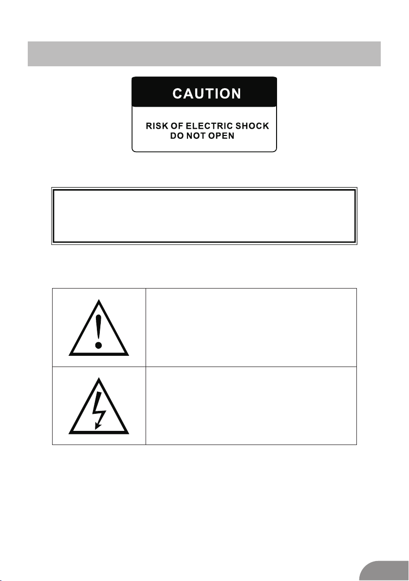
Safety Information
MAY HAVE RIS K OF ELE CTRI C SHOC K ,IF DO ANY CHANGE OR
ADJUST.D O NOT OPEN THE BAC K CABI NET.PLEASE CONTACT
SERV ICE CE NTER F OR ANY PROBL EM
THIS MA RK REM IND AND AL ERT USER M UST
OPERATE TH E TV SE T COR RECT LY
ACCOR DING TO THE USE R MUAN AL.
IN CASE AN Y DAM AGE.
THIS MA RK IS IN DIAC ATE THE TV S ET IS
SENSI TIVE E LECT RONI C PRODUCT.
PLEAS E AVOID WATER OR WE T, INCAS E
OF FIRE O R ELEC TIC SH OCK. DO NOT
OPEN THE BAC K CABI NET. IF ANY
PROBL EM.P LEAS E CALL NEA REST
SERV ICE CE NTER .
2
Page 4

Important Safety Precautions
1. Read t hese i nstr ucti ons.
2. Keep t hese i nstr ucti ons.
3. Heed a ll war ning s.
4. Foll ow all i nstr ucti ons.
5. Do not u se thi s appa ratu s near w ater.
6. Clea n only w ith dr y clot h.
7. Do not b lock a ny ven tila tion o penings. Inst all in a ccor danc e with t he
manuf actu rer’s i nstr uctions.
8. Do not i nsta ll nea r any he at sou rces such as radi ator s, hea t regi ster s, stoves, or
other a ppar atus ( incl udin g amplifiers) that pr oduc e heat .
9. Do not d efea t the sa fety p urpose of the polariz ed or gr ound ing- type p lug. A
polar ized p lug ha s two bl ades w ith one wider than the ot her. A grounding type pl ug
has two b lade s and th ird gr ound ing prong. The wide bl ade or t hird p rong a re
provi ded fo r your s afet y. When the provided pl ug doe s not fi t into y our ou tlet,
consu lt an el ectr icia n for replacement of th e obso lete o utle t.
10. Pro tect t he pow er cor d from being walked on or p inch ed, pa rtic ular ly at plugs,
conve nien ce rec epta cles , and the point whe re the y exit f rom th e appa ratus.
11. Onl y use at tach ment s/ac cessories spe cifi ed by th e manu fact urer.
12. Use o nly wi th the c art, s tand, tripod, b rack et, or t able s peci fied by the
manuf actu rer, or s old wi th the apparatu s. Whe n a cart i s used caution when
movin g the ca rt/a pparatus combinat ion to a void i njur y tip- over.
13. Unp lug th is app arat us dur ing lightning storm s or whe n unus ed for l ong pe riods
of time .
14. Ref er all s ervi cing t o qual ified service perso nnel . Serv icin g is required when the
appar atus h as bee n dama ged in a ny way, such as power-s uppl y cord o r plug i s
damag ed, li quid h as bee n spil led or objects have fal len in to the a ppar atus , the
appar atus h as bee n expo sed to rain or moisture , does n ot ope rate n orma lly, or has
been dr oppe d. Warni ng to re duce the risk of fire or el ectr ic sho ck, do n ot expose
this ap para tus to r ain or m oisture.
15. The apparatus shall be disconnected from the mains by placing the power/standby
switc h in the s tand by pos ition and unplugging the power cord of the apparatus from
the AC mai ns rec epta cle.
16. The socket-out shall be installed near the equipment and shall be easily accessible.
17. Th is pro duct s houl d neve r be placed in a built-in i nsta llat ion su ch as a bo okcase
or rack u nles s prop er ven tilation is provide d or the manufacturer's instructions have
been ad here d to.
18. Appa ratu s shal l not be e xpos ed to dripping or splas hing .
19. Do no t plac e any so urce s of dan ger on the apparatus (e .g. li quid f ille d objects,
light ed can dles ).
20. Wall or C eili ng Mou ntin g - The a ppliance should be mo unte d to a wal l or cei ling
only as r ecom mend ed by th e manu facturer.
21. Nev er pla ce the TV, remot e control or batterie s near n aked f lame s or oth er
heat so urce s, inc ludi ng direct sunli ght. To preve nt the s prea d of fire, keep
candl es or ot her fl ames a way from the TV, remo te con trol a nd bat teri es at
all tim es.
22. Th e USB te rmin al sho uld be l oaded with 0.5 A un der no rmal o peration.
3
Page 5
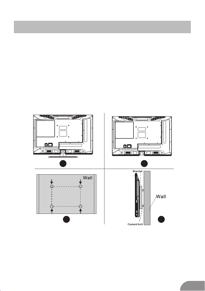
TV Bracket assemble
Fix the T V on the w all
1.Fir st,p ut the TV on th e tabl e smoothly and pu t some s oft cloth on th e tabl e to avo id
scrat chin g the sc reen .
2.Use r the sc rew dr iver t o take off the screws wh ich ar e fixe d on the b otto m stand
(the di rect ion of t he arr ow, refer to the ptoto1) .And take off the bottom stand(please
ta ke off the screws and bottom stand carefully).
3.Mak e one br acke t whic h can fi x on the wall accor ding t o the si ze of ar row di rection
of phot o2 and p hoto 3.
4.Dri ll fou r hole s prop erly o n the wall (the size only f or ref eren ce) an d put into four
screw s.(o ptio nal pa rts) Drill four holes properly on the wall (the size only for reference)
and put i nto fo ur scr ews. (optional parts)
5.acc ordi ng to th e step 4 ,use the screwdrive r to loc k the sc rew on t he bac k of the TV.
then ha ng the TV on th e wall .
1 2
VOLVOL+
-
CH
-
SOURCEMENUCH+
3
4
Note:
1.The b rack et fix ed on th e wall i s optional part .
2.whe n you as semb le the TV, there s hould be no other articles on the around and front
and ple ase ke ep the d ista nce from other articl es.
3.Whe n asse mble t he TV, ple ase as k the career man to fix in or der to a void t he dan ger.
4.The f ixin g pict ure is o nly for reference.
5.Ple ase fo llow t he use m anua l about bracket assem ble to f ix the TV.
6.Att ach th e moun ting b racket from the VESA com pati ble wa ll mou ntin g kit.
4
Page 6

TV Buttons And Terminal Interface
TV Buttons
Note: The fo llow ing is o nly fu nctional schemati c, And th e actu al pos itio n and
arran geme nt of di ffe rent models may be differe nt.
:Tu rn ON/ OFF Po wer.
SOURC E:Ex tern al Sig nal In put Selection .
MENU: Disp lay Ma in MEN U And Con firm MENU Item Se lect ion.
CH+/- :Sel ecti ng Cha nnel .
VOL+/ -:Ad just ing Vol ume.
Terminal Interface
Note: The fo llow ing ar e the va rious terminal inte rfac e, the a ctua l posi tion and
arran geme nt, th e numb er of different mode ls may b e differe nt.
INP UT
VIDE O R L
OUT PUT
VIDE O R L
INP UT
Y Pb Pr
HDM I
AV inp ut
Ext ernal AV Si gn al I npu t And
Rel evant R ith/L eft Sou nd Chan nel
AV out pu t
Ext ernal AV Si gn al o utp ut And
Rel evant R ight/ Left So und Cha nnel
(So me mode ls with out thi s inter face)
Y Pb Pr i np ut
Con nect to t he comp osite t ermin al of
you r DVD/V CR
(So me mode ls with out thi s inter face)
HDM I input
Dig ital si gnal in put fro m HDMI vi deo
con necto r.
ANT 7 5
Con nect th e anten nal/c adle tv i nput
(75 /VHF/ UHF)
VGA i npu t
PC an alog si gnal in put
PC AU DIO I NPUT
VGA in put and a udio in put whe n VGA
inp ut
EAR PHONE o utput
Whe n earph ones ar e plugg ed in,
spe akers a re disa bled
USB i nput
Con nect a US B devic e here to p lay
its m edia fi les.
SCA RT inpu t
sta ndard ,it sup ports c ompos ite and
RGB signa l input .lt is a co nnect ion
for e urope an
(So me mode ls with out thi s inter face)
5
Page 7

External device connection diagram
DV D
Set-t op b ox es
INP UT
VIDE O R L
AV inp ut c on ne ct io n
AV inp ut c on ne ct io n
HDM I
HDMI in pu t co nn ec ti on
INP UT
Y Pb Pr
AV inp ut c on ne ct io n
USB con ne ct io n
HDM I
INP UT
VIDE O R L
OUT PUT
VIDE O R L
AV out pu t co nn ec ti on
Set-t op b ox es
SCART c on ne ct io n
TV co nn ec ti on
6
Page 8

Install And Connect TV
Set you r TV
To put your TV in a fi rm pla ce whi ch can
bear th e weig ht of th e TV.
To avoid da nger, p leas e don’ t expo se the
TV near w ater o r heat ing pl ace (s uch as
light , cand le, he atin g mach ine),do not block
the ven tila tion a t the ba ck of TV.
3
FM ANT
TV si gnal ou tput
2
TV ANT
1
Conne ct ant enna a nd pow er
1.Con nect t he ant enna cable to the antenna
socke t on the b ack of t he TV.
2.To plug t he pow er cor d of TV ( AC 100 240V~ 5 0/60 Hz).
Turn on T V
3.Pre ss the p ower b utto n of the TV the
indic atio n ligh t will t urn to g reen. if it is
on stan dby mo de (th e ligh t is red),press
the pow er but ton on t he rem ote control
to turn o n the TV.
Note:
Pictu re for r efer ence p urpo ses only.
TV Stand Installation Instructions
1.Op en the c arto n and re move the TV
and sca tter ed acc esso ries a nd base
(some m odel s with out ba se).
2.to av oid th e inju ry of th e TV, cove red
with a soft mattress, put it on the table, face
down on a soft mattress, t he base of the
neck is f ixed o n the TV with s crew s.
3.screw the base and connected to the TV.
4. the in stal lati on is co mple te.
1
3
2
4
7
Page 9

TV Menu
Input Sou rce
Input So ur ce
TV
AV
YPb Pr
HDM I
PC
Med ia
ENTER
Ent er
Ent er
Note: The ab ove is f or ref eren ce only, to
preva il any k ind
Press SOURCE to display the input source list.
Press ▼/▲ t o high ligh t the in put source
and pre ss ENT ER to co nfir m.
Press E XIT to hide t he On- Scre en menu,
or it wil l disappear after seconds. (The way
to set the disappeared time: MENU - TIME
Menu - OS D Timer )
Channel M enu
NTSC Ch anne l Menu
CHAN NE L
Tune Ty pe Air
Aut o Tuning
Tune Type
Cable /Air
Auto Tuning
Auto Tun i n g wi l l se a r c h fo r ava i l a ble
chan n e ls a n d pro g r ams. P re ss▼/▲ to
sele c t A u t o Tu n ing, t he n pr e s s OK t o
star t aut o sear c h . If y ou w a n t to s top
sear c h ing, p r ess M E NU o r EXI T, a n d
pres s to c o nfirm o r to c ance l .
Channel Tuning
TV : 5 Pr og ra mm e(s)
44%... 433.75MHZ (TV)
Menu
ATV Man ual Tuning
ATV Ma nual Tuni ng
-
Cur rent CH 1
Col or Syst em PAL
Sou nd Syst em DK
Fin e-Tune 4 9.75M HZ
AFC O ff
Sea rch
+
Mov e Men u Ent er
ENTER
Exi t
PAL Channe l Menu
CHAN NE L
Mov e Men u Ent er
Note : The Channel Men u is av ail abl e onl y
in TV mo de, and the item is t he de fau lt
when p res sin g MEN U, if y ou wa nt vi ew
the Pi ctu re/ Sou nd/ Time/Op tio n Men u,
plea se pr ess t o sel ect .
Aut o Tuning
ATV Ma nual Tun ing
Pro gramm e Edit
ENTER
Exi t
Menu
Curre nt CH
Set the channel number
Color s yste m
Select the color system(PAL/SE CAM/
NTSC)
Sound S yste m
Select the sound system (DK/ BG/I )
Fine- Turn
Adjust the frequency of the chann el fin ely.
AFC
Autom atic F ine tu ning .
Searc h
Press ENTER to search down from the current
frequ ency, and pr ess EN TER to s earch up.
8
Page 10

TV Menu
Progr amm Ed it
Pro gramm E dit
Dele te Ren ame Mov e
FAV
FAV
ENTER
Ent er
Ent er
Fav
Fav
Men u
Men u
Skip
The fou r colo red ke y is the s hortcut key for
progr ammi ng the c hann el.
First p ress ▼/▲ t o high ligh t the channel
you wan t to del ete or r enam e or mo v e or
skip, t hen:
Press t he Red b utto n to del ete the channel.
Press t he Gre en but ton to e nter the
renam e stat e, the npre ss to select the
word yo u want t o chan ge, an d ▼/▲ to
selec t word .
Press t he Yell ow but ton to s et the channel
to mo ving state. then p ress ▼/▲ t o mo ve
it to the p osit ion yo u want t o put.
Press t he Blu e butt on to sk ip the select
chann el. (Your TV set w ill sk ip the c hannel
autom atic ally w hen us ing CH +/- to view
the cha nnel s.)
Fav Add or D elet e the ch anne l to you r faver
ate lis t.
Mediu m
Gives w hite c olor s a neut ral ti nt.
War m
Gives w hite c olor s a red ti nt.
Noise R educ tion
Off/ Low/ Midd le/H igh
You can clear up the input signal by setting
the ite m.
Sound Men u
SOUN D
Mov e Men u Ent er
Sound M ode
Standard/Music/Movie/Sports/User/Only
in this m ode, Tr e ble an d Bass c an be
adjus ted. )
Bass
Adjus t the lo w freq uenc y soun ds.
Treble
Adjus t the hi gh fre quen cy sou nds.
Balan ce
Adjus t the le vel of s ound c omin g from
the lef t and ri ght sp eake rs.
Auto Volume
Press L /R to se t or can cel. W hen set
on, it wi ll lev el out t he sou nd bei ng heard
when su dden c hang es in vo lume
occur d urin g comm erci al bre aks or
chann el cha nges .
Adjus ting t he Bas s/Tre ble/Balance
1 Selec t Soun d Mode a s User.
2 Highl ight t he ite m and pr ess ▼/▲ to
displ ay the s ub-m enu, t hen pr ess
to adju st the v alue .
Sou nd Mode S tanda rd
Treb le 50
Bas s 50
Bal ance 0
Aut o Volume O ff
ENTER
Exi t
9
Page 11

TV Menu
Picture M enu
PICT UR E
Mov e Men u Ent er
Pict ure M ode
High lig ht th e ite m and P ress ENTER o r
to ent er th e sub -me nu, t hat sho ws
the pi ctu re mo de yo u can c hoose:
Dyna mic /St and ard /Mild/Us er
Pres s PMO DE on t he re mot e control
to sel ect p ict ure m ode d irectly.
Cont ras t/B rig htn ess/Colo r/Tint
(NTS C onl y)/ Sha rpn ess
High lig ht th e ite m and p ress , and a
proc ess b ar ap pea rs, t hen press
to adj ust t he va lue .
Pres s MEN U or EX IT to hid e the
on-s cre en me nu.
Note : Those sett ing s can b e adj ust ed
only w hen t he Pi ctu re Mo de is set to Use r.
Cont ras t
Adju st th e whi te le vel o f the pictur e
Brig htn ess
Adju st da rkn ess o f bla ck section s in th e
pict ure .
Colo r
Adju st th e col or in ten sity of the pi ctu re.
Tint
Adju st th e hue (Re d,G reen,Blu e) of t he
pict ure .
Shar pne ss
Obje ct ed ges a re en han ced for pict ure d
etai l.
Colo r Temper atu re
Sele ct th e col or te mpe rature tha t you f eel
comf ort abl e.
Cool
Give s whi te co lor s a blu e tint.
Pic ture Mo de S tanda rd
Con trast 50
Bri ghtne ss 50
Col or 50
Tint 5 0
Sha rpnes s 5 0
Col or Temper ature Med ium
Noi se Redu ction Middle
ECO M ode Off
ENTER
Exi t
.
Time Menu
TIME
Mov e Men u Ent er
Sleep Ti mer
Selec t the ti me in mi nute s(off,10min,
20min ,30m in,6 0min ,90m in,120min,
180mi n,24 0min ) that y ou wan t the
TV to shu t off a utom atic ally a fter you
set the t ime. C ance l by set ting it to Off
Auto Sl eep
Selec t the ti me in ho urs( off ,3h,4h,5h)
that yo u want t he TV t o rema in on af ter
your la st ope rati on. Ca ncel b y setting it
to Off .
OSD Ti me r
Selec t the ti me in se cond s(5s ,10s,15s,
20s,2 5s,3 0s,) t hat yo u want the On-
Scree n Men re main d ispl ay aft er your last
opera tion .
Slee p Timer O ff
Auto Sleep O ff
OSD Ti mer 10s
ENTER
Exi t
Option Me nu
OPTI ON
Mov e Men u Ent er
OSD La ngua ge Engl ish
Asp ect Rat io 16:9
Blu e Scree n Off
Key Lo ck Off
Cap tion Off
Par ent Con trol
Res et
Sof tware Up date (USB)
ENTER
Exi t
10
Page 12

TV Menu
OSD L a ng uage
Set t h e OSD d ispla y lang u a ge.
Aspe c t Rat i o
Sele c t the s uitab l e asp e c t Ra t i o n. ( 4 : 3 /
16:9 / Z o om1/Z o o m 2).
Blue S cr een
Set the back grou nd co lor to blue or black
when h aving n o inp u t si g n a l.
Key L o ck
Set to prevent it from being used by young
chil d r e n, o r othe r unex p e c ted u s i ng.
Capt i o n
Select from belo w clo sed-c aptio n mod es.
CC1,2,3,4 Displays corresponding caption
ch a n nels o f a a n al og p r o g ram. ( U suall y
be s e t to C c1 fo r most p rogra m s . )
Text1,2,3,4 Displays cor r e s p o n d i n g t e x t
serv i c e ch a n n el o f a a n a l og p r o g ram.
Pare n t Con t r o l
For d e ta il p l e a se r e f e r to p age 7 .
Rese t
Reca l l the d efaul t sett i n g .
Soft w a r e Up d a t e(USB )
Update your TV set. Select the software in
the r o ot of y our U S B me m o r y, a n d pre s s
ENTE R l .
Parent Co ntrol(NTSC)
Set P asswo rd
Loc k Syste m ON
TV
MPAA R
Can ada Eng lish PG
Can ada Fre nch G
Menu
Se t P as s w o r d F ir s t y ou s ho u l d e n t e r
th e c or r e c t o ld p as s w o r d t h e n e nt e r n ew
pa s s w o r d t wi c e .
Lo c k S ys t e m
Se t t he l oc k s ys t e m O N or OFF.
TV
Th e T V rating compose of t wo a s p e c t s :
ag e - b a s e d a nd c on t e n t - b a s e d . P a g e 9
MA P P
Th i s s ys t e m d ef i n e s t he r at i n g c o n t r o l
wh i c h c om e f ro m M PAA rules.
G
Ge n e r a l a ud i e n c e . All ages a d mitted
PG
Pa r e n t a l g ui d a n c e
PG - 1 3
Pa r e n t s s tr o n g l y c a u t i o n e d . S om e
ma t e r i a l m ay b e inappro p r i a t e f or
ch i l d r e n u nd e r 1 3.
R
Re s t r i c t e d . C hi l d r e n u n d e r 1 7 requir e
ac c o m p a n y i n g p a r e n t o r adult guardian.
NC - 1 7
No o ne 1 7 and under a a d m i t t e d .
X
Ad u l t a ud i e n c e o nl y
Ca n a d a E ng l i s h T h e r a t i n g s a re f or
pr o g r a m s w hi c h a re u si n g E ng l i s h r a t i n g
sy s t e m .
C
Ch i l d r e n
C8 +
Ch i l d r e n 8 years and o l d e r
G
Ge n e r a l p ro g r a m m i n g
PG
Pa r e n t a l g ui d a n c e
14 +
Vi e w e r s 1 4 a nd o ld e r
18 +
Ad u l t p ro g r a m m i n g
Canada French
Th e r at i n g s a re f or p ro g r a m s w h i c h a re
us i n g F re n c h r at i n g s ys t e m .
G
Ge n e r a l
8 ans+
No t r ec o m m e n d e d f or y ou n g e r c h i l d r e n
13 a ns +
No t r ec o m m e n d e d f or c hi l d r e n u n d e r
ag e 1 3
16 a ns +
Not recommended for a g e s u n d e r 1 6
18 a ns +
Th i s p ro g r a m i s restric t e d t o adults
11
Page 13

TV Menu
TV rati ng(N TSC)
TV ra ting
ALL
TV-Y
TV-Y 7
TV-G
TV-P G
TV-1 4
TV-M A
FV
ALL
ALL
D
ALL
ALL
ALL
Men u
L
S
V
V
V
D
L
S
L
S
TV-Y
General audience
TV-Y7
Parental guidance suggested
TV-G
Parents strongly cautioned
TV-PG
Restricte d
TV-14
No one 17 a n d under admitted
TV-MA
Adult audience only
FV
Fantasy violence
D
Suggestive dialogue
L
Strong language
S
Sexual situations
V
Vi o l e n c e
N o t e : T h e c o n t e n t r a t i ng s w i l l i ncrease d e pe nding on the level of the
age-b a s ed ratin g . For e x a mp le ,
a progr a m with a T V-PG V ( v iolence)
rating may contain moderate violence,
while a TV-14 V (v iolence)
rating m a y contai n intens e vi o lence.
So lock i n g a hig h e r level o p ti on will
automat i c a lly lock i n g the
op tions that has more sensitive level.
Hotel M enu( Opti onal )
OPTI ON
Mov e Men u Ent er
HOTE L
Mov e Men u Ent er
OSD L angua ge Engl ish
Asp ect Rat io 16:9
Blu e Scree n Off
Key L ock Off
Cap tion Off
Par ent Con trol
Hot el Mode
Res et
Sof tware U pdate (USB)
ENTER
Hot el Mode O n
Sou rce Loc k
Def ault So urce Off
Def ault Pr og 1
Max Vo lume 10 0
Cha nnel lo ck Off
Def ault Vol ume 20
Cle ar Lock
Set P asswo rd
ENTER
Exi t
Exi t
Hotel M ode
Set hot el mo de ON or O FF.
No t e : T he f o llowing sett i n gs w o rk o n ly
when Ho tel M ode is s et to b e ON.
Sourc e Loc k
Lock th e inp ut sou rce w hich you wa nt.
Defau lt So urce
Set the default input source when turning
on your TV.
Defau lt Pr og
Set the d efa ult program when turning on
your TV.
Max Vol ume
Set the m ax vo lume t hat y ou can adjust.
Chann el lo ck
Lock th e cha nnel w hic h you prefe red.
Defau lt Volume
Set the default volume for every time you
open th e TV, the d efau lt vo lume is 20.
Clear L ock
Recall the default setti ngs in hotel mode.
Set Pas swo rd
Set the p ass word a s you l ike.
12
Page 14

PC Menu
Media Menu
Scree n Menu
SCREEN
Mov e Men u Ent er
Aut o Adj ust
Hor izont al Pos. 50
Vert ical Pos . 50
Cloc k 50
Pha se 99
ENTER
Exi t
Auto Adju st
Autom atic ally a djus t Cloc k, Phase,
H-Pos itio n, and V- Posi tion s ettings.
Horiz onta l Pos.
Shift t he scr een up o r down .
Vertic al Pos .
Shift t he scr een le ft or ri ght.
Clock
Adjus t the in tern al sam plin g clock rate.
Phase
Adjus t the in tern al sig nal ph ase.
The col or of th e icon m eans w heth er
your TV has de tect ed a USB m emor y or
not. Bu le: Yes; G ray: N o;
Press
to sele ct Pho to/M usic /
Movie /Tex t icon a nd ENT ER to en ter
the USB m emor y.
13
Page 15

Help
14
Page 16

Machine Technical Specifications
Scre en S ize
16”
19”/ 20 ”
22”
24”
32”
39”/ 40 ”
42”
46”
50”
Scre en S ize
16”
19”/ 20 ”
22”
24”
26”
32”
39”/ 40 ”
42”
46”
50”
TV Sys te m
PAL/ NTS C
PAL/ NTS C
PAL/ NTS C
PAL/ NTS C
PAL/ NTS C
PAL/ NTS C
PAL/ NTS C
PAL/ NTS C
PAL/ NTS C
power Con sump tion
(LE D)
24W
36W
36W
36W/ 48 W
56W/ 65 W/100 W
70W/ 75 W
70W
110W
135W
Preset Channel s
PAL: 0-199 ,NTSC :AIR 2- 69
CAB LE1-1 25
PAL: 0-199 ,NTSC :AIR 2- 69
CAB LE1-1 25
PAL: 0-199 ,NTSC :AIR 2- 69
CAB LE1-1 25
PAL: 0-199 ,NTSC :AIR 2- 69
CAB LE1-1 25
PAL: 0-199 ,NTSC :AIR 2- 69
CAB LE1-1 25
PAL: 0-199 N TSC:A IR 2-69
CAB LE1-1 25
PAL: 0-199 ,NTSC :AIR 2- 69
CAB LE1-1 25
PAL: 0-199 ,NTSC :AIR 2- 69
CAB LE1-1 25
PAL: 0-199 ,NTSC :AIR 2- 69
CAB LE1-1 25
power Con sump tion
(LCD)
36W
48W
48W
60W
100W
100W /1 35W
135W
175W
280W
Spea ke r Outpu t
5W+5 W
5W+5 W
5W+5 W
5W+5 W
10W+ 10 W
10W+ 10 W
10W+ 10 W
10W+ 10 W
10W+ 10 W
Main a cc essor ie s
User's manual x1
Remote controller x1
AAA Batteries x2
LIFE T IME 60, 000 H rs
15
Page 17

Remote Controller
1.POWER:
2.MUTE:
3.0-9:
4.
5.
6.S.MODE:
7.SLEEP:
8. MTS: Press to select the MTS mode.(for example,
9.P.MODE:
BTSC,MONO,STEREO .eg )MTS ,
10.MENU:
11.SOURCE:
12.
13.ENTER:
14.EXIT:
15.INFO:
ENTER
MTS
ASPECT
REPEAT
SLEEP
GOTO
SUB .PG
HOLD
YELLOW
P.MODE S.MODE
MENU SOURCE
EXIT
ROOT
FAV FAV- FAV+
CANCEL
INDEX
REVEAL SIZE
RED GREEN
INFO
15
FREEZE
ON/OFF
MIX
CYAN
CAUTION:
Batteries installed in the unit should not be exposed to excessive heat such as sunshine,fire and the like.
16
Page 18

Remote Controller
16.VOL+:
17.ROOT:
When playing the photo or VIDEO,if you
press ROOT,then it will stop playing and return
to the current catalogue,in USB mode.
18.VOL-:
19.FR:
USB mode.
FAV: Press to add or remove your favorite
channels under TV menu
20.PLAY/PAUSE:
,in USB mode.
21.PREV:
USB mode.
FAV+: Press to switch your favorite channels
under TV menu
22.STOP:
USB mode.
23.GREEN/RED/YELLOW/CYAN:
Under the menu corresponding to the TV,
press the button according to the color
display to enter
RED:Exchange
GREEN:Insert
YELLOW:Copy
BLUE:Delete
24.CH+:
25.REPEAT: Repeat
26.CH-:
27.FF:
USB mode.
FAV-: Press to switch your favorite channels
under TV menu
28.
29.NEXT:
FREEZE:Image still
30.GOTO:Skip
31.
32.
33.
34.
ASPECT:
ON/OFF
35.
36.
USB mode.
16
18
17
27
19
20
22
31
32
23
ENTER
MTS
ASPECT
REPEAT
SLEEP
GOTO
SUB .PG
HOLD
YELLOW
P.MODE S.MODE
MENU SOURCE
EXIT
ROOT
FAV FAV- FAV+
INDEX
CANCEL
REVEAL SIZE
RED GREEN
INFO
FREEZE
ON/OFF
MIX
CYAN
24
34
26
25
30
21
29
28
35
36
33
17
 Loading...