


T-Max® Manager/Plus and T-Max®3A/F/I User’s Guide Page i
TABLE OF CONTENTS
1. OVERVIEW..........................................................................................................................2
1.1 C
OMPONENTS
..................................................................................................................2
1.2 S
PECIFICATIONS
...............................................................................................................3
1.3 O
PTIONAL
PC H
ARDWARE AND SOFTWARE REQUIREMENTS
...........................................4
2. QUICK INSTALLATION....................................................................................................4
2.1 C
ONNECTING THE
T-MAX® T
IMING SYSTEM
..................................................................4
2.2 S
ETTING THE ADDRESSES
. ...............................................................................................4
2.3 A
DJUSTING THE INTERCOM VOLUME IN EACH TANNING ROOM
.......................................5
3. INSTALLATION..................................................................................................................5
3.1 W
IRING
............................................................................................................................5
3.2 T-MAX® 3A/I/M
ASTER
...................................................................................................6
3.3 T-MAX® MGR/P
LUS
.......................................................................................................6
3.4 T-MAX®3A/F/I...............................................................................................................6
4. INITIAL CONFIGURATION.............................................................................................6
4.1 S
ETTING THE ADDRESS ON THE
T-MAX®3A/F/I..............................................................6
4.2 T-MAX® MGR/P
LUS
.......................................................................................................7
5. MANUAL OPERATION .....................................................................................................7
5.1 D
ESCRIPTION
...................................................................................................................7
5.2 I
NITIAL CONFIGURATION
..................................................................................................7
5.2.1 Setting up the T-Max® Mgr/Plus............................................................................7
5.2.2 Parameter Numbers................................................................................................8
5.2.3 Security Levels ......................................................................................................10
5.3 S
TARTING
A S
ESSION
.....................................................................................................11
5.4 C
ANCELING
A S
ESSION
..................................................................................................11
5.5 P
AUSING
A S
ESSION
.......................................................................................................11
5.6 C
LEAN ROOM
.................................................................................................................11
5.7 C
HECKING BED STATUS
.................................................................................................12
6. COMPUTER OPERATION..............................................................................................13
6.1 I
NSTALLING
ADNET 2000™.........................................................................................13
6.1.1 Creating a Short Cut on Your Windows® Desktop...............................................13
6.2 S
ETTING UP
ADNET 2000™ TO R
UN WITH A
T-MAX® MGR.....................................15
6.2.1 Selecting the COM Port........................................................................................16
6.2.2 Setting the Delay and Auto Start Mode.................................................................17
6.3 RUNNING ADNET 2000™.........................................................................................17
6.3.1 Comms Status Screen............................................................................................17
6.3.2 Manager Access Screen........................................................................................19
6.3.3 Starting a Session..................................................................................................19

T-Max® Manager/Plus and T-Max®3A/F/I User’s Guide Page ii
6.3.4 Canceling a Session..............................................................................................19
6.3.5 Getting and Changing Parameters.......................................................................20
6.3.6 MANAGER UTILITIES.........................................................................................21
6.3.7 Download Program from PC to Manager............................................................21
6.3.8 Edit Manager Setup ..............................................................................................21
6.3.9 Rescan Manager ...................................................................................................22
6.3.10 Auto Address the T-Max® System.........................................................................22
6.4 S
ETTING UP
ADNET 2000™
FOR THE
T-MAX® I
NTERCOM SYSTEM
...........................23
6.4.1 Determine were your ADNET 2000™ Program files are stored. .........................24
6.4.2 Setting up ADNET 2000™ to use the Recorded Messages...................................25
6.4.3 Recording Your In-Room Messages......................................................................26
7. THE INTERCOM...............................................................................................................30
7.1 S
ETTING UP THE INTERCOM
...........................................................................................30
7.1.1 Adjusting the Volume on the T-Max® 3A/I/Master...............................................30
7.2 C
ALLING A ROOM FROM THE FRONT DESK
....................................................................30
7.3 C
ALLING THE FRONT DESK FROM A ROOM
. ...................................................................30
7.4 A
UTO SHUTOFF
..............................................................................................................31
7.5 C
ALL WAITING
...............................................................................................................31
7.6 E
MERGENCY CALL
.........................................................................................................31
8. EXPANSION.......................................................................................................................32
8.1 A
DDING BEDS
................................................................................................................32
8.1.1 The ADNET-Repeater™ (optional).......................................................................32
8.2 A
DDING
T-MAX® M
ANAGER/PLUS’S
............................................................................32
9. T-MAX®3A/F/I OVERVIEW ...........................................................................................33
9.1 I
NSTALLING THE
T-MAX® 3A/F/I..................................................................................33
9.2 S
ETTING PARAMETERS ON THE
T-MAX®3A/F/I............................................................33
9.2.1 Setting the Address................................................................................................34
9.2.2 Setting Delay Time................................................................................................34
10. USING THE T-MAX® 3A/F/I AS AN INDEPENDENT TIMER..............................34
10.1 S
TARTING A SESSION
.....................................................................................................34
10.2 P
AUSING A SESSION
.......................................................................................................35
10.3 C
ANCELING A SESSION
...................................................................................................35
11. OTHER FEATURES AND OPTIONS..........................................................................35
11.1 C
LEAN ROOM
.................................................................................................................35
11.2 C
OOL DOWN MODE
.......................................................................................................36
11.3 T-MAX® M
ONITORS
.....................................................................................................36
11.4 T-MAX® S
ENTRY
™ (O
PTIONAL
)..................................................................................36
11.5 H
IGH PRESSURE (SINGLE-SIDE
) B
EDS
............................................................................37
11.5.1 Installing External Speaker (Optional).................................................................37
11.6 C
ONNECTING A REMOTE PUSH BUTTON TO THE
T-MAX®3A/F/I (O
PTIONAL
)...............37

T-Max® Manager/Plus and T-Max®3A/F/I User’s Guide Page iii
11.7 T-MAX® E
NCLOSURE (OPTIONAL
)................................................................................38
12. FIGURES.........................................................................................................................39
12.1 F
IGURE
A - F
RONT VIEW OF THE
T-MAX® 3A/F/I .......................................................39
12.2 F
IGURE
B - F
RONT VIEW OF THE
T-MAX® 3A/I/M
ASTER
............................................39
12.3 F
IGURE
C - R
EAR VIEW OF
T-MAX®3A/F/I
AND AUDIO CIRCUIT BOARD
....................40
12.4 F
IGURE
D - J99
AND
J100 J
UMPER SETTINGS
................................................................41
12.5 F
IGURE
E - C
ONNECTING THE
T-MAX® S
ENTRY
™.......................................................41
12.6 F
IGURE
F - C
ONNECTING TO LOWER CURRENT BEDS
....................................................42
12.7 F
IGURE
G - T
HE
T-MAX® MGR/P
LUS
...........................................................................42
12.8 F
IGURE
H - R
EAR VIEW OF
T-MAX® M
ANAGER/PLUS
.................................................43
12.9 F
IGURE
I - C
ONNECTING THE
T-MAX® S
ERIES
.............................................................44
12.10 F
IGURE
J - M
ULTIPLE CONFIGURATIONS
....................................................................45
12.11 F
IGURE
K - M
ODULAR CABLE PINOUTS
.....................................................................46
12.12 F
IGURE
L - E
XAMPLE OF AN EXTERNAL PUSH BUTTON CIRCUIT
.............................46
13. TROUBLE SHOOTING................................................................................................47
13.1 T
ROUBLE SHOOTING
......................................................................................................47
13.2 E
RROR CODES
................................................................................................................49
14. INDEX.............................................................................................................................. 50
(C) COPYRIGHT 1999 By Salon Systems, Inc.
The information in this manual is believed to be correct. However, Salon Systems, Inc. assumes no responsibility for any
errors herein. This information is subject to change without notice, and should not be construed as a commitment by Salon
Systems, Inc.
WARRANTY
This product is warranted against defective materials and workmanship for a period of two years from date of purchase. In
the event the product fails to perform, it may be returned; Shipping Paid, to the factory to be serviced or replaced at the
factory's discretion. Salon Systems, Inc. will pay to ship the repaired or replaced product by the shipping means of our
choosing. Returns will not be accepted without a Return Authorization Number assigned by the factory.
It is a Condition of Sale that the user of Salon Systems Inc.'s products assumes all risk and responsibility of use and
indemnifies Salon Systems, Inc. against all damages. Salon Systems, Inc. is not liable for loss of profits, lost savings,
special, incidental, consequential, indirect or other similar damages arising from breach of warranty, breach of contract,
negligence, or other legal action even if Salon System, Inc. or its agent has been advised of the possibility of such
damages, or for any claim brought against you by another party. This warranty allocates risks of product failure between
the Purchaser and Salon Systems, Inc. Salon System, Inc.’s hardware pricing reflects this allocation of risk and the
limitations of liability contained in this warranty
It is a violation of the stated warranty to cut or modify the provided modular cables supplied with the T-Max® Series
Timers. Connecting the T-Max® Series to third party timers not approved by Salon Systems, Inc. also violates the stated
warranty. Contact your dealer or Salon Systems, Inc. if you are not sure if the timer that you are connecting is an approved
timer.

T-Max® Manager/Plus and T-Max®3A/F/I User’s Guide Page 2
1. OVERVIEW
Congratulations on your p urchase of Salon Systems, Inc.’s T-Max® Series of tanni ng bed
timers with the built in intercom. The T-Max® is designed for complete automation and
control of your tanning equipment. It is also an excellent manual backup system in case your
PC fails. The T-Max® Mgr/Plus can be used as a stand-alone unit or can be controlled with a
computer using a number of popular software packages. Manual operation is accomplished via
front panel controls.
Manual operation is accomplished by pressing the proper sequence of buttons. There are 64
lights, each showing the status of a bed. A 16 key keypad and 16x2 LCD display allows you to
operate the T-Max® Mgr/Plus manually. If the T-Max® Mgr/Plus loses power, the TMax®3A/F/Is can be used as stand alone timers. As long as the T-Max® Mgr/Plus is active
the T-Max®3A/F/Is cannot be used as independent timers. Intercom control is accomplished
by either the tanner pressing the Call button in the tanning room on the T-Max® 3A/F/I or the
salon operator selecting the room to call from the T-Max® Mgr/Plus keypad and using the TMax® 3A/I/Master.
A licensed electrician installing your new system should use this manual. Check for
compliance with local building codes.
1.1 Components
T-Max® Mgr/Plus:
1 T-Max® Mgr/Plus Unit
1 9VDC @ 1A Power Supply
1 RS-232C Cable DB9M-DB9F
1 DB25F-DB9M Comm Port Adapter
1 This Manual
1 T-Max® Utility Software (3.5” diskette)
1 Terminator
T-Max®3A/F/I/ (Sold separately, 1 required for each bed in the salon):
1 T-Max®3A/F/I Timer Interface
1 12VAC @ 1A Transformer
1 T-Max®3A/F/I User’s Guide
1 Modular cable with RJ-22 connectors on both ends
1 Modular cable with RJ-45 connectors on both ends
T-Max®3A/I/Master (Sold separately)
1 T-Max®3A/I Master Timer Interface
1 12VAC @ 1A Transformer
1 T-Max® Intercom User’s Guide
1 Modular cable with RJ-22 connectors on both ends
1 Audio Cable
If any component is missing, contact your dealer.

T-Max® Manager/Plus and T-Max®3A/F/I User’s Guide Page 3
Options:
T-Max® Enclosure™
Attaches to the T-Max®3A/F/I to hang on the wall or set on a desk.
T-Max® Speaker (Optional):
Connects to T-Max®3A/F/I to provide higher alarm indications.
T-Max® Sentry (Optional; 1 required for each T-Max®3A/F/I):
Indicates if bed is not operating properly.
T-Max® Slave Kit (Optional) :
Required for additional slave T-Max® Mgr/Plus.
T-Max® Monitor (Optional):
Provides 64 dual-color lights to show the status of all beds in your salon.
T-Max® Monitor/Plus (Optional):
Provides 16 displays showing bed times and statuses.
ADNET-Repeater (Optional):
Connects in the middle of the daisy chain amplify the communications signal.
1.2 Specifications
T-Max® Mgr/Plus:
Power Supply
IN - 120VAC
OUT – 9VDC @ 1A
Current Draw
800mA
Dimensions
10” x 5.25” x 2”
Communication
T-Max® Mgr/Plus - PC RS-232C, 9600 Baud, 8Bit, 1 Stop Bit, No Parity
T-Max®3A/F/I and T-Max® 3A/I/Master:
Power Supply
IN - 120VAC
OUT - 12V AC @ 1A
Current Draw
800mA
Dimensions:
Cover Plate:
9 W” x 5.175 H”;
T-Max®3A/F/I PCB:
2.87 x H 2.3”D x 7.5” W”
Enclosure: 5.24”H x 9” W x 2.75” D x 2” D
Relay (T-Max® 3A/F/I only):
220VAC @ 5A; SPST Form A
Display:
T-Max® Mgr/Plus: 64 dual color lights showing bed status.
1, 16x2 LCD display shows individual bedtime and status.
T-Max®3A/F/I: 1, 2 digit LED display showing bedtime and status.
T-Max3A/I/Master: 1 dual colored LED display.
Maximum Units:
128 T-Max®3A/F/I’s controlling 128 beds.
8 T-Max® Mgr/Plus’s can be used to control up to 128 beds.
1 Computer can be connected to each T-Max® Mgr/Plus.

T-Max® Manager/Plus and T-Max®3A/F/I User’s Guide Page 4
1.3 Optional PC Hardware and Software Requirements
1) 32KBytes available RAM.
2) 100KBytes available Hard Disk Drive Space.
3) 1 available RS232 port.
4) IBM AT, 286, 386, 486, Pentium or Compatible.
5) Windows® 95/98/NT.
2. Quick Installation
2.1 Connecting the T-Max® Timing System
1) Install a T-Max®3A/F/I in each room. Install the T-Max® Mgr/Plus and the T-Max®
3A/I/Master at the front desk.
2) 2 50’ modular cables (phone type cable) are provided with each T-Max®3A/F/I: 1 with RJ22 connectors and 1 with RJ-45 connectors . Run each from the T-Max® 3A/I/Master location
to T-Max®3A/F/I in the nearest tanning room. Run the other modular cables from room to
room in a daisy-chain fashion (Refer to Figure I Section 12.9).
3) Connect the modular cables to each T-Max®3A/F/I and the T-Max® 3A/I/Master. When
finished each T-Max®3A/F/I should have a modular cable connected to each port, with the
exception of the last T-Max®3A/F/I in the series.
4) Connect the 20’ modular cable with RJ-22 connectors that were provided with the T-Max®
3A/I/Master between the T-Max® Mgr/Plus and the T-Max® 3A/I/Master.
5) Connect the tanning bed to the “J3 Contact” screw terminals on the back of the TMax®3A/F/I.
Important: There may be many wires visible on the tanning bed. Two of these wires are
specifically used for connecting the bed to an external timer. If you are not sure which
two wires to use, refer to t he tanning bed’s manual or contact the be d’s manufacturer.
6) Each T-Max®3A/F/I came with a 12V-power supply. Connect a power supply to the “PWR
IN 9-12V” screw termination block on the back of each T-Max®3A/F/I.
7) Plug each of the T-Max®3A/F/I’s power supplies into a standard 110V-power outlet.
2.2 Setting the Addresses.
8) Apply power to the T-Max® Mgr/Plus (power does not have to be applied to the TMax®3A/I/Master at this point). Wait until the T-Max® Mgr/Plus is done scanning.
9) Press the Menu/Call button on the T-Max® Mgr/Plus. The LCD display will read as
follows: SECURITY/CALL.
10) Press 888 followed by the Enter button.
Each T-Max®3A/F/I will show a 99 on their displays and beep continuously.
11) Go to each room in order (1,2 3, 4, 5, 6 etc.) pressing the Start/Stop buttons in each room
until all displays show a 0 and the alarms stop.

T-Max® Manager/Plus and T-Max®3A/F/I User’s Guide Page 5
As you press the Start/Stop buttons in each room, the Maximum Bed Number on the TMax® Mgr/Plus will automatically count up.
If you wants to skip a room number, press the Next button on the T-Max® Mgr/Plus for
each room you want to skip. For example, to address your salon in following sequence:
1,2,4,5,8 press the Start/Stop buttons in rooms 1and 2. Then go to the T-Max® Mgr/Plus
and press the Next button one time to skip room 3. Press the Start/Stop buttons in rooms 4
and 5. Press the Next button on the T-Max® Mgr/Plus twice to skip rooms 6 and 7.
Finally, press the Start/Stop button on the timer in room 8.
12) Press the Clear or Enter Button on the T-Max® Mgr/Plus.
13) Cycle power to the T-Max® Mgr/Plus. After a short pause, the T-Max® Manger/Plus will
then scan and lights will illuminate for each bed found.
14) Apply power to the T-Max® 3A/I/Master
2.3 Adjusting the Intercom Volume in each Tanning Room
Before screwing the T-Max® 3A/F/Is into the wall, you will want to adjust the volume in
each room for the intercom. Two people will be needed: one at the T-Max® Mgr/Plus and one
in the tanning room.
15) Locate the volume control on the back of the T-Max® 3A/F/I (refer to Figure C, Section
12.3)
16) On the T-Max® Mgr/Plus, press the Call/Menu button. The display will read as follows:
SECURITY/CALL
17) Press 1 followed by the Enter button. The display will read as follows: Talk to Room 1.
The display on the T-Max® 3A/F/I will show two dashes ( -- ).
18) Press the Talk button on the T-Max® 3A/I/Master at the front desk and talk into the
microphone. Release the Talk button to listen.
19) While the person at the front desk is talking, adjust the volume on the T-Max® 3A/F/I in
the tanning room by turning the volume control clockwise or counter clockwise.
20) Once the volume is adjusted to your satisfaction, press Clear on the T-Max® Mgr/Plus to
hang up. The display on the T-Max® 3A/F/I will show a 0.
21) Repeat steps 15-20 for each room in the salon.
Installation is now complete.
3. INSTALLATION
3.1 Wiring
Run the modular cable with RJ-22 connectors and the modular cable with RJ-45 connectors
provided with each T-Max®3A/F/I from the T-Max® 3A/I/Master to the first room. Run the
modular cables from room to room in a daisy chain (Refer to Figure I, Section 12.9).

T-Max® Manager/Plus and T-Max®3A/F/I User’s Guide Page 6
3.2 T-Max® 3A/I/Master
Connect the 12V-power supply provided with the T-Max® 3A/I/Master to the power input on
the T-Max® 3A/I/Master and a 120VAC outlet. Connect the two modular cables going to the
tanning room to the modular connectors on the T-Max® 3A/I/Master (refer Figure I, Section
12.9). You may connect the Audio Cable between the T-Max® 3A/I/Master and the speaker
output on the back of your computer.
3.3 T-Max® Mgr/Plus
Connect the 9V-power supply provided with the T-Max® Mgr/Plus to the power input on the
T-Max® Mgr/Plus and a 120VAC outlet. Connect the 20’ modular cable provided with the TMax® 3A/I/Master between the T-Max® Manager/Plus and the T-Max® 3A/I/ (refer Figure I,
Section 12.9). If you are using a computer connect the RS-232 DB9F-DB9M cable between
the serial port on the T-Max® Mgr/Plus and the serial port on the back of your computer.
3.4 T-Max®3A/F/I
A T-Max®3A/F/I must be connected to each tanning bed and power must be applied. (Refer
to Section 2.1 and Section 12.3-Figure C).
In the first tanning room, connect the modular cable with RJ-22 connectors connected to TMax® 3A/I/Master to one of the modular ports on the back of the T-Max®3A/F/I. Connect
the modular cable with RJ-45 connectors connected to the T-Max® 3A/I/Master to one of the
modular ports on the back of the T-Max®3A/F/I. Connec t the modular cables running to the
next tanning room to the open modular ports. In the second tanning room, connect the modular
cables from the first tanning room to two of the modular ports on the back of the TMax®3A/F/I. Connect the modular cables running to the third room to the open modular
ports. Repeat this until all of the rooms are connected. (Refer to Figure I, Section 12.9, Figure
C, Section 12.3).
4. INITIAL CONFIGURATION
4.1 Setting the Address on the T-Max®3A/F/I
Note: If you are installing new T-Max® system and have just completed Section 2 (Quick
Installation), the addresses are set and you do not need to independently set addresses on the
T-Max®3A/F/Is.
1) Remove power from the T-Max® Mgr/Plus.
2) Apply power to the T-Max®3A/F/I. It should show a 9.9 and an alarm should sound.
If it just shows a 0, go to Step 4.
3) Press and release the Start/Stop button. The display will flash an 8.8 and the alarm will
stop. Press and release the Up button until the display stops flashing and shows a 0.
4) Press and hold the Start/Stop and Up Buttons simultaneously on the T-Max®3A/F/I until a
.1 appears on the display. This should take about 5-6 seconds. Release the buttons.

T-Max® Manager/Plus and T-Max®3A/F/I User’s Guide Page 7
5) Press the Start/Stop button on the display. A flashing number will appear. This is the
address that the timer is currently set to.
6) Press the Up or Down button until the desired address is displayed.
Note: When setting the addresses, remember these three rules:
• Set each T-Max®3A/F/I to a unique address.
• Do not set any T-Max®3A/F/I to address 00.
• If the period is flashing, you are over address 100.
7) Once the desired address is displayed, press and release the Start/Stop button. A solid .1 will be
displayed.
8) Press and hold both the Up and Down buttons until a 0 is displayed.
Repeat Steps 2-8 for each T-Max®3A/F/I that you are manually setting the address on.
4.2 T-Max® Mgr/Plus
1) Make sure all wiring is completed. Refer to Section 3 for wiring instructions.
2) Apply power to the T-Max® Mgr/Plus.
The T-Max® Mgr/Plus will scan for T-Max®3A/F/Is. An amber light will illuminate for
each T-Max®3A/F/I detected. Once scanning is complete, the light will turn green.
5. MANUAL OPERATION
5.1 Description
The T-Max® Mgr/Plus has 64 dual-colored lights showing bed status. Section 5.8 describes
the light indicators. A 16x2 LCD display on the upper right corner of the T- Max® Mgr/Plus
shows bed status and times. A 16 key keypad allows the user to control the salon.
5.2 Initial Configuration
5.2.1
Setting up the T-Max® Mgr/Plus.
1) Apply power to the T-Max® Mgr/Plus. The T-Max® Mgr/Plus will scan the network to
find all T-Max®3A/F/Is.
2) Press the Call/Menu Button. The following message will appear: SECURITY/CALL.
A sheet was provided showing the factory default settings for each security level and
security level descriptions.
3) The following message will appear: GET PARAMS? Press Next.
4) The following message will appear: SEND PARAMS? Press Next
5) The following message will appear: MGR PARAMS? Press Enter.
6) The following message will appear: MGR DELAY TIME. Enter the delay time in minutes,
followed by the Enter button.

T-Max® Manager/Plus and T-Max®3A/F/I User’s Guide Page 8
If you want the session to start right away, enter a delay of 0. The maximum setting for
delay is 10 minutes. This setting is for every bed in the salon.
7) The following message will appear: MGR START MODE. Enter the desired Auto Start
Mode followed by the Enter button.
This setting is for every bed in the salon. If a 1 is entered, then the bed will energize
immediately after the delay time expires. If a 0 is entered, the bed will not energize when
the delay time expires, but session time will begin counting down. If a 2 is entered, then
the T-Max® Mgr/Plus is set to infinite delay and session will not start until the Start/Stop
button is pressed on the T-Max®3A/F/I.
Note: If the T-Max® Mgr/Plus is controlled by a computer, the Delay and Auto Start
mode are controlled by the computer’s software unless you set the T-Max® Mgr/Plus to
infinite delay. If the T-Max® Mgr/Plus is set to Infinite Delay, the Delay set in the TMax® Mgr/Plus or the PC will be ignored.
8) The following message will appear: MGR MAX BED. Enter the maximum bed number
followed by the Enter key.
This number must be equal to or higher than the highest address that a T-Max®3A/F/I is
set to. For example if you have six beds, but are addressing the T-Max®3A/F/Is to
1,2,3,4,5, and 8, then set the maximum bed number to 8.
9) The following message will appear: MANAGER NUM. Enter the T-Max® Mgr/Plus
address, followed by the Enter button.
Up to 8 T-Max® Mgr/Plus’s can be connected in a single salon. One T-Max® Mgr/Plus
must be set to address 0. All slave T-Max® Mgr/Plus’s must be set to an address other
than 0. Set each Slave T-Max® Mgr/Plus to a unique address.
10) The following message will appear: MGR RE-SCAN TIME. Press the Enter key.
11) The following message will appear: MAX SLAVE. This should be the same number as the
highest address you have set any slave T-Max® Mgr/Plus’s to. For example, i f you ha ve three
T-Max® Mgr/Plus’s, one must be set to address 0 (Master). If one slave T-Max® Mgr/Plus is
set to 1 and the other is set to 3, the MAX slave value should be 3. The highest value that can
be entered is 7. Enter the MAX SLAVE number followed by the Enter button.
The LCD display will then read “Saving Params”.
5.2.2
Parameter Numbers
Parameters are values stored in each T-Max®3A/F/Is such as Lamp Hours, Session Counts,
etc. Table 1 shows the parameter numbers and details about them.
To get or change parameters, do the following:
1) Press the bed number you want to manipulate followed by the Enter Key. The bed number
and its status will appear.
2) Press the Call/Menu button. The following message will appear: SECURITY/CALL.
3) Enter the security number for level 3 followed by the enter key.

T-Max® Manager/Plus and T-Max®3A/F/I User’s Guide Page 9
4) The following message will appear: GET PARAMS? If you just want to observe current
values, press Enter. If you want to send new values, press Next, then go to Step 6.
5) The following message will appear: WHICH PARAMETER? Enter the parameter number
from Table 1 followed by the Enter key.
The top line on the LCD display will show the bed number. The second line will show the
value for the parameter you checked. Press Clear to exit.
6) Press the Next button.
7) The following message will appear: SEND PARAMS? Press the Enter button.
8) The following message will appear: WHICH PARAMETER? Enter the parameter number
from Table 1 followed by the Enter button.
9) The following message will appear: SEND WHAT DATA? Enter the value that you want
to store in that timer followed by the Enter button. Press Clear to exit.

T-Max® Manager/Plus and T-Max®3A/F/I User’s Guide Page 10
Table 1 - Parameter Numbers for Getting and Sending Parameters.
Parm # Description Max # Default Notes
1 Address 255 254 Address of T-Max®3A/F/I
2 Beep Mode 1 0 Used for High Power beds. 0=Alarm only, 1=Alarm and Flip
3 Delay Time 5 0 Delay in minutes stored in the T-Max®3A/F/I.
4 Current Sense 1 0 For the T-Max® Sentry™ Option. 0=Disabled, 1=Enabled.
5 Session Counts 65535 0 Total session counts for T-Max®3A/F/Is.
6 Lamp Hours 65535 0 Bulb hours for each bed.
7 Bed Hours 65535 0 Number of hours a bed is on.
8 Manual Session
Counts
65535 0 Counts the number of sessions the T-Max®3A/F/I has run while in Stand
Alone Mode
9 Clean Room 1 1 0 = Clean Room Disabled, 1 = Enabled
10 Manual Lockout 1 0 0 = Stand Alone Enabled, 1 = Disabled
13 Cool Down
Mode
10 0 0 = Disabled, 1-10=Enabled. Time delay in minutes allowing bed to
cool.
15 Fixed Session
Counts
65535 0 Counts number of sessions ran through the T-Max®3A/F/I. This value
cannot be changed at all. Used as point of reference.
17 Clean Clear 1 0 0 = Press and hold the Up button for 3-4 seconds to clear the clean room.
1 = Press and release the Up button to clear instantly
20 External Speaker 1 0 0 = Speaker on T-Max®3A/F/I, 1 = External Speaker will be used.
21 Pause Mode 1 0 0 = When session is pause, session time continues to count down. 1 =
When session is paused, session time stops counting down.
22 Auto Shut Off 1 0 0 = When intercom is active, the bed will stay on. 1 = When intercom is
active, bed will turn off and go to pause mode
5.2.3
Security Levels
There are 5 security levels on the T-Max® Mgr/Plus. When the Call/Menu button is pressed,
the display will prompt you for a security number. Refer to the enclosed Security number
sheet on how to change security numbers. The description of these levels follows:
Level 0 - Computer Control Level
Sessions can be monitored, but not started manually.
Level 1 - Employee Level
Session operation only. No parameters can be observed or changed.
Level 2 - Supervisor’s Level
Parameter values can be observed but not changed.
Level 3 - Manager’s Level
Parameters can be observed and changed. Security numbers cannot be changed.
Level 4 - Owner’s Level
This level allows the changing of Security numbers for access.
Asterisks will be displayed on the lower left corner of the LCD indicating which security
number was last entered, a single asterisk for level 1, 2 for level 2 and 3 for level 3.
When changing Security numbers, make sure the number you choose is higher than 128. Any
number under 128 is used by the intercom to call a room. Below are a list of other security
numbers that are reserved and what they are reserved for:
778 – Error Codes

T-Max® Manager/Plus and T-Max®3A/F/I User’s Guide Page 11
779 – Real Time Clock (Not used on the T-Max® Series, but still reserved)
888 – Auto Addressing
911 – Emergency Call
999 – Rescanning the T-Max® Series
5.3 Starting A Session
You must be at Security Level 1, 2 or 3 to start sessions manually.
1) Press the bed number you want to start, followed by the Enter button.
2) Press the Time button. The display will read “Enter Session Time”
3) Enter the Session time you want followed by the Enter button.
If a delay other than 0 has been entered, the delay will count down on the display. If an
Infinite delay has been set up, the session time will show but will not count down.
DELAY will show for status. Once the customer presses the Start/Stop button on the TMax®3A/F/I in the room, the session will start. The display will show the session time
counting down and the status will say ON.
5.4 Canceling A Session
1) Press the bed number that you want to cancel, followed by the Enter button.
2) Press the Time button. The message “Enter the Time” will appear on the LCD display.
3) Press the Enter button (without entering any time).
If the clean room is enabled and the delay time has expired, DIRTY will appear on the
display. The Status LED will be Red. Once the clean room has been cleared, the display
on the T-Max® Mgr/Plus will show READY and the Status LED will turn Green.
5.5 Pausing A Session
To pause a session, press the Start/Stop button on the T-Max®3A/F/I at the tanning bed. The
flashing period will stop flashing and stay illuminated. The T-Max® Mgr/Plus display will
show PAUSE on the display.
Note: The session time will continue to count and display will reflect the remaining session
time.
To restart the session, press the Start/Stop button on the T-Max®3A/F/I. The period will
continue flashing and the Status on the T-Max® Mgr/Plus will change to ON.
5.6 Clean Room
Once the session time has elapsed or has been canceled, the display will show two periods
with no numbers, which is an indication that the room needs to be cleaned. Press and hold the
Up button on the T-Max® 3A/F/I in the tanning room until a 0 appears on the display to clear
the clean room. For a complete description of Clean Room, refer to Section 11.1.

T-Max® Manager/Plus and T-Max®3A/F/I User’s Guide Page 12
5.7 Checking Bed Status
To check the status of a bed, glance at the 64 dual colored lights.
Green = Bed is ready for a new session.
Red = Bed needs to be cleaned.
Off = Bed is not available.
Flashing Red = There are less than two minutes left in a session.
Flashing Green = Bed is in the Cool Down Mode.
Yellow = Scanning or Error.
Flashing Yellow = Intercom Call Request Pending
To check time remaining in an active session, press the bed number followed by Enter.
To check the times on all beds, press the Next or Prev (previous) button repeatedly.

T-Max® Manager/Plus and T-Max®3A/F/I User’s Guide Page 13
6. COMPUTER OPERATION
6.1 Installing ADNET 2000™
1) Place the ADNET 2000™ diskette in drive A.
2) Click Start with your left mouse button.
3) Click Run with your left mouse button.
4) Type the following: a:setup.
5) Click OK (or press Enter)
6) Follow the directions on the screen
6.1.1
Creating a Short Cut on Your Windows® Desktop.
1) Place your mouse anywhere on the desktop screen. Make sure it is not over an existing
Icon.

T-Max® Manager/Plus and T-Max®3A/F/I User’s Guide Page 14
2) Press the right mouse button. A window will appear.
3) Move the mouse pointer to New. A second window will appear.
4) Move the mouse to Shortcut and click it with your left mouse button. A Create Shortcut
window will appear.

T-Max® Manager/Plus and T-Max®3A/F/I User’s Guide Page 15
5) Click Browse. A Browse window will appear.
6) Double click the folder that you installed ADNET 2000™ into with your left mouse button.
The factory default folder is c:\program files\adi\ADNET2000. This is the folder the
ADNET 2000™ files will probably be under.
7) Double click the ADNET 2000™ icon with your left mouse button. The Create Shortcut
window will reappear.
8) Click Next with your left mouse button.
9) Click Finished with your left mouse button.
10) The ADNET 2000™ icon will appear where you placed your mouse in Step One.
6.2 Setting Up ADNET 2000™ To Run With a T-Max® Mgr
Make sure ADNET 2000™ is properly installed and the icon is created as described in
Section 1.

T-Max® Manager/Plus and T-Max®3A/F/I User’s Guide Page 16
Double click the ADNET 2000™ Icon with your left mouse button. The ADNET 2000™
window will appear:
ADNET 2000™ Window
6.2.1
Selecting the COM Port
1) Click Setup with your left mouse button. The Setup window will appear
Setup Window

T-Max® Manager/Plus and T-Max®3A/F/I User’s Guide Page 17
2) Click the COM port that you are connected to with your left mouse button. A black circle
will appear beside that COM port you have selected.
6.2.2
Setting the Delay and Auto Start Mo de
1) Place the mouse in the window to the left of “Default Session Delay Time” and click the
left mouse button. A flashing cursor will appear in the window.
2) Use the Delete or Backspace key to delete the number currently in the window and type in
the desired delay time.
The longest the delay time can be is 10 minutes. If no delay time is desired (Start session
immediately) enter a 0. If infinite delay time is desired (allowing the customer as much
time as they want to get undressed), go to Step 3.
3) In the Auto Start Setting window, place the mouse in the circle and click the left mouse
button to set the Auto Start Setting.
After Delay Time Start with Lamps OFF
– After the delay time expires, the session time
will start but the lamps will not come on. The display on the timer will show the
remaining session time. The Start/Stop button must be pressed to turn the lamps on.
After Delay Time Start with Lamps ON
- After the delay time expires, the session time
will start and the lamps will come on automatically. The display on the timer will show
the remaining session time.
No Delay, Wait For Button Press in Room
– The timer will show the session time in the
room but will not count down. The Start/Stop button on the timer in the room must be
pressed to energize the lamps and start the session time counting down.
5) Click OK. The ADNET 2000™ window will reappear
6.3 RUNNING ADNET 2000™
1) Make sure the T-Max® Manager is properly installed and connected to the computer. Refer
to the T-Max® Ma nager User’s guide.
2) Click Start. The Comms Status and Manager Access Screens will appear.
Comms Status Window
6.3.1
Comms Status Screen
The Comms status screen shows the status of communications between ADNET 2000™ and
the T-Max® Mgr/Plus.

T-Max® Manager/Plus and T-Max®3A/F/I User’s Guide Page 18
RX and TX show communication between the computer and the T-Max® Mgr/Plus.
These should be flashing unevenly.
Firmware version is the ROM version stored inside the T-Max® Mgr/Plus.
Application is the RAM software version inside the T-Max® Mgr/Plus r.
If the boxes below TX and RX do not flash or Firmware version reads 99.99, then there is no
communications between the PC and the T-Max® Mgr/Plus. Make sure the T-Max®
Mgr/Plus is connected to the PC and power is applied to the T-Max® Mgr/Plus. If there is still
no communications, click Close with the left mouse button, click Setup from the ADNET
2000™ window and try another Comm port setting.
Manager Access Window

T-Max® Manager/Plus and T-Max®3A/F/I User’s Guide Page 19
6.3.2
Manager Access Screen
The upper left corner of the Manager Access screen shows <Manager Status> and <Bed
Parameter Utilities>. These are discussed in Sections 6.3.6 and 6.3.5. The right side shows the
beds you have and their st atuses.
The left side of the screen is an activity log. This is to aid in trouble shooting. The right side of
the screen shows bed status.
Bed - Bed number
Time - current time.
Status - Status if the timer (Ready, On, Pause, Delay, Dirty or Cool)
Type - Type of timer in each room.
Vers - Software version in each timer.
Max - Maximum time for each timer.
6.3.3
Starting a Session.
1) Place the mouse in the Time window beside the bed number that you want to start.
2) Press the Left mouse button.
3) The Start Session window will appear. Enter the bed number you want to start and the
desired session time in minutes.
4) Click Yes. If you don’t want to start a session, click No.
5) The session will start and the display will show the bedtime and status.
6.3.4
Canceling a Session.
1) Place the mouse in the Time window beside the bed number you want to Cancel.
2) Press the Left mouse button.
3) A cancel session window will appear. If the displayed bed is correct, press Yes. If the
displayed bed is not the bed you want to cancel, enter the correct bed number click Yes with
your left mouse button. If you don’t want to cancel any session, click No.

T-Max® Manager/Plus and T-Max®3A/F/I User’s Guide Page 20
6.3.5
Getting and Changing Parameters
1) Click Bed Parameter Utilities with your left mouse button.
2) Click Upload Parameter from Beds. The Timer Parameter Access screen will appear:
Timer Parameter Access Window
3) To change a parameter, move the mouse to the window beside Password and click it with
your left mouse button. A flashing cursor will appear in the window. Enter the password (see
the attached password sheet provided with this manual). As you enter the password, an (*) will
appear for each character.
After the password has been entered, place the mouse in the window where you want to
change the parameter. For example, if you want to change parameter 5 for bed 2, place
the mouse in the white window below Param 5 and beside 2 as the arrow shows in the
Timer Parameter Access window.
4) Click the left mouse button.
5) A Change Parameter Data window will appear. Enter the value you want to change the
parameter to then click OK with your left mouse button. If you don’t want to change the
parameter value, click Cancel.
6) The change parameter window will change the show the new value for that parameter.
7) When you are done changing parameters, click Close with your left mouse button.

T-Max® Manager/Plus and T-Max®3A/F/I User’s Guide Page 21
Table 4 - Parameter Table
Parm # Description Max # Default Notes
1 Address 255 254 Address of T-Max®3A/F/I
2 Beep Mode 1 0 Used for High Power beds. 0=Alarm only, 1=Alarm and Flip
3 Delay Time 5 0 Delay in minutes stored in the T-Max®3A/F/I.
4 Current Sense 1 0 For the T-Max® Sentry™ Option. 0=Disabled, 1=Enabled.
5 Session Counts 65535 0 Total session counts for T-Max®3A/F/Is.
6 Lamp Hours 65535 0 Bulb hours for each bed.
7 Bed Hours 65535 0 Number of hours a bed is on.
8 Manual Session
Counts
65535 0 Counts the number of sessions the T-Max®3A/F/I has run while in Stand
Alone Mode
9 Clean Room 1 1 0 = Clean Room Disabled, 1 = Enabled
10 Manual Lockout 1 0 0 = Stand Alone Enabled, 1 = Disabled
13 Cool Down
Mode
10 0 0 = Disabled, 1-10=Enabled. Time delay in minutes allowing bed to
cool.
15 Fixed Session
Counts
65535 0 Counts number of sessions ran through the T-Max®3A/F/I. This value
cannot be changed at all. Used as point of reference.
17 Clean Clear 1 0 0 = Press and hold the Up button for 3-4 seconds to clear the clean room.
1 = Press and release the Up button to clear instantly
20 External Speaker 1 0 0 = Speaker on T-Max®3A/F/I, 1 = External Speaker will be used.
21 Pause Mode 1 0 0 = When session is pause, session time continues to count down. 1 =
When session is paused, session time stops counting down.
22 Auto Shut Off 1 0 0 = When intercom is active, the bed will stay on. 1 = When intercom is
active, bed will turn off and go to pause mode
6.3.6
MANAGER UTILITIES
Click Manager Utilities with your left mouse button. The window will appear with the
following options:
Download Program from PC to Manager
- Allows you to load the T-Max® Mgr/Plus with
new software
Edit Manager Setup
- Allows you to change T-Max® M gr/Plus Setting for manual use.
Rescan timers
- Allows you to have the T-Max® Mgr/Plus rescan the timer network
Auto Address
- Allows you to Auto Address the entire salon.
6.3.7
Download Program from PC to Manager
Click Manager Utilities then Download Program from PC to Manager with your left mouse
button.
ADNET 2000™ will load the T-Max® Mgr/Plus with the latest software. The Activity
Log will show Sending 256 bytes to different addresses. After the download is complete a
Manager Restart window will appear. The T-Max® Mgr/Plus will rescan. A status bar
will scroll across the window. Once this is complete, you can start new sessions.
6.3.8
Edit Manager Setup
1) Click Manager Utilities then Edit Manager Setup with your left mouse button.

T-Max® Manager/Plus and T-Max®3A/F/I User’s Guide Page 22
The Manager screen will appear:
Currently only P# 1,2,3 and 4 are used. These settings are changed in the T-Max®
Mgr/Plus for use when the T-Max® Mgr/Plus is used manually in the event of a computer
failure. These settings do not effect the settings described in section 2.2.
When changes are complete, click the X on the upper right corner of the window with your
left mouse button.
6.3.9
Rescan Manager
Click Manager Utilities then Rescan Manager with your left mouse button. The T-Max®
Mgr/Plus will rescan the timer network.
6.3.10
Auto Address the T-Max® System
Auto Address will allow you to reset the addresses on the timers in the room. This is typically
done on initial installation, when adding tanning beds or when you want to change the room
numbers in your salon.
Note: Make sure no one is tanning before selecting this option.
Delay
Auto Start
Maximum Bed Number
Display Mode
All others not used

T-Max® Manager/Plus and T-Max®3A/F/I User’s Guide Page 23
1) Click Manager Utilities then Auto Address the T-Max® System with your left mouse
button.
2) A window will appear with the following message: Proceed with Auto Address of Entire
System? (Make sure there are no active sessions).
3) Click OK with your left mouse button of you want to proceed. Click Cancel of you do not
want to auto address the salon.
Once you click OK, the Manager Access screen will disappear and the ADNET 2000™
screen will appear. Each timer in the salon will show a 99 and be sounding an alarm. The
T-Max® Manager/Plus LCD display will show Auto Addressing Bed 00. Go to each
timer in order that you want the salon to be and press the Start/Stop buttons along the
way. Each timer will go to a 0. Make sure you press the Start/Stop buttons in order that
you want the salon addressed. Go to room 1 first, then room 2, room 3 etc.
The T-Max® Mgr/Plus LCD display will show Auto Addressing Bed XXX. XXX will be
one number higher then the number of beds addressed. Press the Enter button on the TMax® Manager/Pl us keypad.
4) On your computer, press the Start button with your left mouse button. The Manager Access
screen will reappear with the new configuration being displayed.
6.4 Setting Up ADNET 2000™ for the T-Max® Intercom System
ADNET 2000™ can be used to send automated messages to each timer while the timer is in
Delay, while the Clean Room indication is showing or when the timer is in cool down mode.
You must have a sound card and microphone to use this feature.

T-Max® Manager/Plus and T-Max®3A/F/I User’s Guide Page 24
6.4.1
Determine were your ADNET 2000™ Program files are stored.
From the ADNET 2000™ window, click Setup. The following screen will appear:
The bottom of the window shows the Current Directory. This is the directory that the sound
files must be saved to. Write this path down.

T-Max® Manager/Plus and T-Max®3A/F/I User’s Guide Page 25
6.4.2
Setting up ADNET 2000™ to use the Recorded Messages
From the ADNET 2000™ window, click Setup with your left mouse button. Then click
Intercom Setup with your left mouse button. The following screen will appear:
Click the circle to left of the message for what messages you want to play in the tanning room.
Message During Delay:
Don’t Play Messages During D elay
– No messages will be played in any room while any
timer is in delay.
Play SAME Message or ALL Rooms
– The message recorded under the Beforeall.wav
file name will be sounded in all rooms while that timer is in Delay.
Play DIFFERENT Message for Individual Rooms
– The files recorded under the file
names of Before1.wav, Before2.wav etc. will be sounded in Room1, Room2. etc.
respectively while the timer is in delay.
Message During Cool Down and Dirty Room:
Don’t Play Messages During Cool Down and Dirty Room
– No messages will be played
in any room while any timer is in Cool Down or Dirty Room after the session ends.
Play SAME Message or ALL Rooms
– The message recorded under the Afterall.wav file
name will be sounded in all rooms while that timer is in Cool Down Mode or Dirty Room
after a session ends.
Play DIFFERENT Message for Individual Rooms
– The files recorded under the file
names of After1.wav, After2.wav etc. will be sounded in Room1, Room2. etc.
respectively while the timer is in Cool Down Mode or Dirty Room after session ends.
Click OK to exit the Intercom Setup.

T-Max® Manager/Plus and T-Max®3A/F/I User’s Guide Page 26
6.4.3
Recording Your In-Room Messages
1) Find the Sound Recorder. Typically you will click Start, go to Programs then go to
Accessories then go to Multimedia then click Sound Recorder with your left mouse button.
Note: If you are running Windo ws® 98, the Sound Recorder may be in your
Entertainment folder under Accessories.

T-Max® Manager/Plus and T-Max®3A/F/I User’s Guide Page 27
2) The following screen will appear:
3) Press F
ile with your left mouse button. A window will appear.
4) Move your mouse down to New and click it with your left mouse button.
6) Click the record button with your left mouse button and record your message into the
computer’s microphone.
7) Click the Stop button as soon as your are done speaking.
We recommend that your message is no longer than 10-15 seconds.
8) Click F
ile with your left mouse button. A window will appear.
Rewind Fast Play Stop Record
Forward

T-Max® Manager/Plus and T-Max®3A/F/I User’s Guide Page 28
9) Click Save As with your left mouse button. A Save As window will appear.
10) In the Save i
n window, click the down arrow to the right and find the file folder where the
ADNET 2000™ program files are located. This is the same as the path you wrote down in
Section 6.4.1.
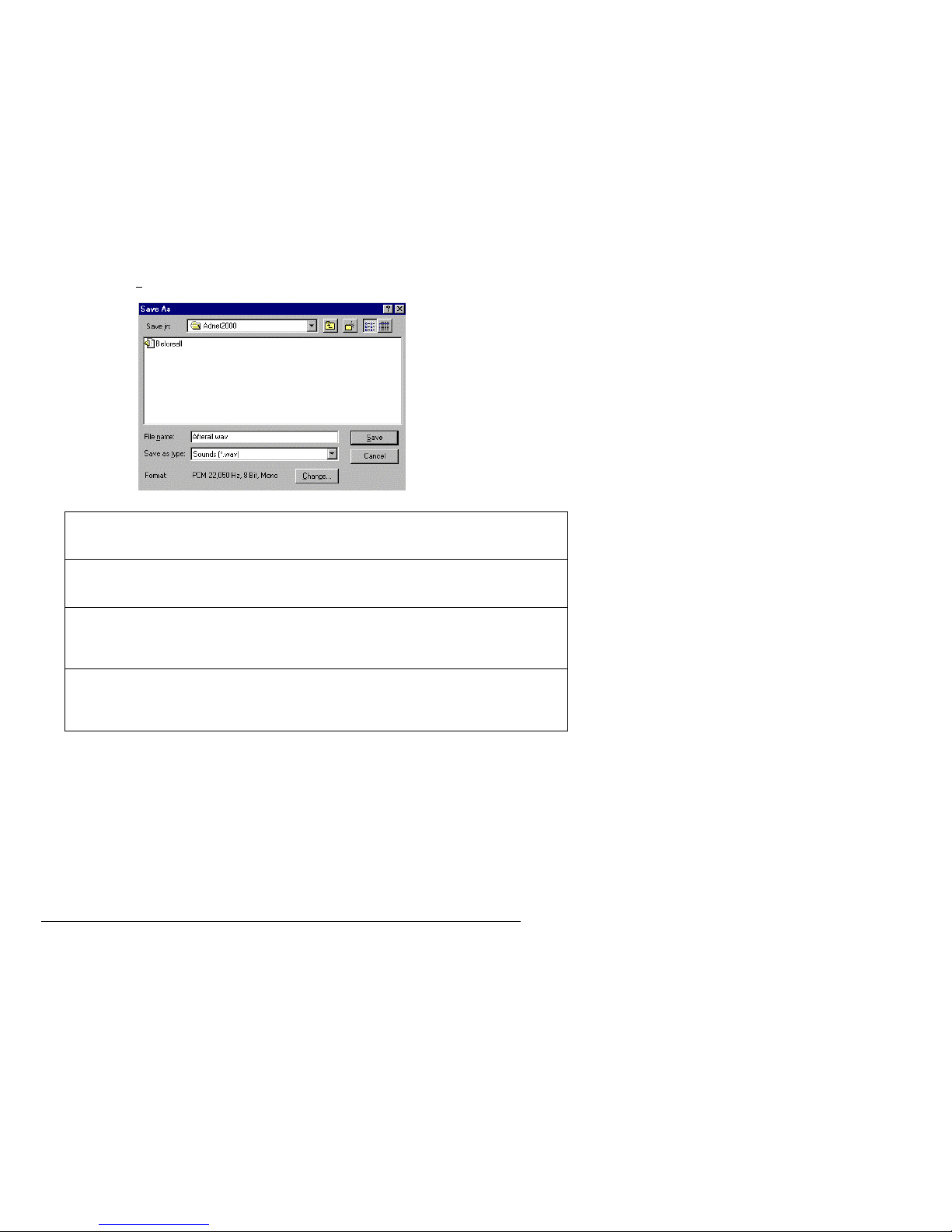
T-Max® Manager/Plus and T-Max®3A/F/I User’s Guide Page 29
11) In the File name window, type in the file name that fits the format described below:
File Name Description
Before#.wav Message sounded while room # is in delay. If you selected Play DIFFERENT
Message for Individual Rooms under Message During Delay in Section 6.4.2,
then this is the file name you give your recording.
Beforeall.wav
If you want the same message sounded in all rooms while in delay. If you
selected Play SAME Message for ALL Rooms under Message During Delay in
Section 6.4.2, then this is the file name you give your recording.
After#.wav
Message sounded while room 3 is in dirty or cool down mode. If you selected
Play DIFFERENT Message for Individual Rooms under Message Duri ng Cool
Down and Dirty Room in Section 6.4.2, then this is the file name you give your
recording.
Afterall.wav
If you want the same message sounded in all rooms in dirty or cool down mode.
If you selected Play SAME Message for ALL Rooms under Message During
Cool Down and Dirty Room in Section 6.4.2, then this is the file name you give
your recording.
If the message you just recorded is the message you want to play in room 4 while room 4
is in delay, the file name MUST be named as follows: Before4.wav. This will allow you
to play a different message for each bed.
If the file you just recorded is to be played in every room while any room is in delay, the
file MUST be named as follows: Beforeall.wav.
If the message you just recorded is the message you want to play in room 6 while room 6
is in dirty room or cool down mode, the file MUST be named as follows: After6.wav.
If the file you just recorded is to be played in every room while any room is in dirty room
or cool down mode, the file MUST be named as follows: Afterall.wav. This will allow
you to play a different message for each bed.

T-Max® Manager/Plus and T-Max®3A/F/I User’s Guide Page 30
9) Repeat Steps 1-8 until all messages are recorded are recorded.
7. THE INTERCOM
7.1 Setting Up the Intercom
Install the Series as described in Section 2. Section 2.3 describes how to adjust the volume in each
T-Max® 3A/F/I in each room.
7.1.1
Adjusting the Volume on the T-Max® 3A/I/Master
1) Press the Call/Menu button on the T-Max® Mgr/Plus. The LCD display will read as
follows: SECURITY/CALL
2) Press 1 followed by the Enter button.
3) Have a person go into room 1 you called and start talking.
4) Press the Volume Up or Down button on the T-Max® 3A/I/Master to adjust the volume.
5) Press the Volume Up and Down buttons on the T-Max® 3A/F/I simultaneously to save the
volume level.
7.2 Calling a Room from the Front Desk
1) Press the Call/Menu button on the T-Max® Mgr/Plus. The LCD display will read as
follows: SECURITY/CALL.
2) Press the room number you want to talk to followed by the Enter button.
The light on the T-Max® 3A/I/Master will flash Red. The timer on the tanning room will
go to double dash ( -- ). The light on the T-Max® 3A/I/Master will flash red.
If Parameter 22 is set to a 1, the tanning bed will automatically turn off and the timer will
go to pause (the session time will continue to count down). If parameter 22 is set to a 0,
the tanning bed will stay on.
To talk to the room, press and hold the talk button on the T-Max® 3A/I/Master. Hold this
button while talking. Release the button to listen. No button needs to be pushed in the
room to talk.
Press Clear on the T-Max® Mgr/Plus to hang up the intercom. The display on the TMax® 3A/F/I will show the remaining session time and the light on the T-Max®
3A/I/Master will turn green.
7.3 Calling the Front Desk from a Room.
1) Press and release the Call button on the T-Max® 3A/F/I in the tanning room.
The T-Max® 3A/F/I will show two dashes. If parameter 22 is set to a 1, the tanning bed
will turn off and the timer will go to a Pause mode (session time will continue to count
down). The light on the T-Max 3A/I/Master will flash red.

T-Max® Manager/Plus and T-Max®3A/F/I User’s Guide Page 31
2) The T-Max® Manager LCD display will read as follows: Talk to Room # (the room
number calling the front desk). The light on the T-Max® 3A/F/I will flash Red while the
intercom is active.
3) The front desk operator must press and hold the Talk button on the T-Max® 3A/I/Master to
talk, and release the Talk button to listen. The tanner in the room does not press any buttons.
7.4 Auto Shutoff
When a salon operator calls a tanning room, or the tanning room calls the front desk, you have
the choice of having the t anning bed turn off automatically or stay on if a session is running.
Parameter 22 controls this feature. Refer to Section 5.2.2 for changing parameter numbers.
0 = Tanning bed will stay on if the room is called.
1 = Tanning bed will automatically turn off if the room is called.
If parameter 22 is set to a 1, when the room is called, the T-Max® 3A/F/I will go into the
Pause mode. The display will show 2 dashes and the period will stop flashing and stay
illuminated. Session time will continue to count down. When the intercom is hung up at
the front desk, the display will show the remaining session time. The tanner must press the
Start/Stop button to turn the tanning bed back on.
7.5 Call Waiting
If another room calls the front desk while the intercom is active with another room, the display
on the T-Max® 3A/F/I in the tanning room will show flashing dashes. A yellow light will flash
on the T-Max® Mana ger/Plus showing which room is trying to call. The T-Max® Mgr/Plus
will beep while a call is pending. If parameter 22 is set to a 1, the tanning bed will not yet turn
off.
Once the conversation is done with the first room, press clear on the T-Max® Mgr/Plus to
hang up. The room waiting will automatically connect and be displayed on the T-Max®
Mgr/Plus display. The flashing dashes in the room will turn to solid dashes. If parameter 22 is
set to a 1, the tanning bed will turn off.
Press Clear on the T-Max® Mgr/Plus to hang up. The display will return to the room status.
The T-Max®3A/F/I in the tanning room will show the remaining session time. If the tanning
bed is off, the customer must press the Start/Stop button to turn the tanning bed back on.
7.6 Emergency Call
In the event of a salon emergency, an Emergency Call feature has been implemented.
IMPORTANT: When the Emergency Call in implemented, every active session will be
canceled and the tanner will not be able to restart the session.
1) Press the Call/Menu button on the T-Max® Mgr/Plus. The following message will appear
on the LCD display: SECURITY/CALL.
2) Press 911 followed by the Enter button.

T-Max® Manager/Plus and T-Max®3A/F/I User’s Guide Page 32
Every active session in the salon will be canceled and all tanning beds will turn off. Every
T-Max® 3A/F/I will show two dashes. The people in the room will not be able to speak to
the front desk.
3) Press and hold the Talk button on the T-Max® 3A/F/I and speak into the microphone. The
announcement will be broadcast to every room in the salon that has a T-Max® 3A/F/I
installed.
To cancel the Emergency Call, press the Clear button on the T-Max® Mgr/Plus.
8. EXPANSION
8.1 Adding Beds
IMPORTANT: Maximum times for each be d is programmed into the T-Ma x®3A/F /I at
the factory. When ordering the T-Max®3A/F/Is, make sure you have the maximum time
for each bed available.
One T-Max® Mgr/Plus will control up to 64 beds. To add beds, simply purchase one TMax®3A/F/I for each bed that you add.
Setting the address on each new T-Max®3A/F/I
Refer to Section 4.1 on setting the address on the T-Max®3A/F/I. Make sure the address set
on each additional T-Max®3A/F/I is not the same as a T-Max®3A/F/I you already have.
Setting the max. bed number on the T-Max® Mgr/Plus
If you are using a computer, refer to Section 6.3.8 on setting the Max. Bed Number. If you are
not using a computer, refer to Section 5.2.1.
8.1.1
The ADNET-Repeater™ (optional)
The T-Max® Series will connect up 128 beds. However after about 25 tanning beds, you may
experience communications errors. If this happens, you may need to add a T-Max® Repeater.
The ADNET-Repeater™ connects anywhere in the daisy chain and amplifies the
communications signal down the rest of the line. (See Figure I, Section 12.9)
8.2 Adding T-Max® Manager/Plus’s
The T-Max® Seri es can have up to 8 T-Max® Mgr/Plus’s. You must order a T-Max® Slave
Kit for each salve T-Max® Mgr/Plus. A computer can be added to each T-Max® Mgr/Plus.
Refer to Section 3.2 for instructions on connecting a PC to each T-Max® Mgr/Plus. To add TMax® Mgr/Plus’s, follow these steps:
1) Remove the back from each Slave T-Max® Mgr/ Plus and remove the JP1 and JP2 Jumpers
(See Figure H, Section 12.8 ). Replace the back.
2) Apply power to each Slave T-Max® Mgr/Plus.
3) Refer to Section 5.2.1 on setting the address on the each Slave T-Max® Mgr/Plus. Make
sure each Slave T-Max® Mgr/Plus has a unique address.

T-Max® Manager/Plus and T-Max®3A/F/I User’s Guide Page 33
4) Connect each T-Max® Slave Kit to each T-Max® Mgr/Plus and to the cable connected to
the first tanning room.
5) Apply power to the Master T-Max® Mgr/Plus
6) Refer to Section 5.2.1 and Set the Max. Slave Setting on the Master T-Max® Mgr/Plus.
7) Cycle power to the Master T-Max® Mgr.
Note: Each Slave T-Max® Mgr/Plus must be powered up before you power the Master T-
Max® Mgr/Plus. Each computer can be used to cancel a session, start a session, and monitor
all sessions. However, parameters (bulb hours, session counts, etc.) can only be monitored and
changed from the Master T-Max® Mgr/Plus.
9. T-MAX®3A/F/I OVERVIEW
Each T-Max®3A/F/I can individually control a tanning bed in the event of a front desk
failure. Operation is accomplished via front panel controls. The T-Max®3A/F/I comes fitted
with a wall plate and fits into a 4- wide wall box.
9.1 Installing the T-Max® 3A/F/I
Refer to Section 2.1.
9.2 Setting Parameters on the T-Max®3A/F/I
Note: If you are using a T-Max® Mgr/Plus and multiple T-Max®3A/F/Is, remove power from
the T-Max® Mgr/Plus then cycle power to each T-Max®3A/F/I. Keep power removed from
the T-Max® Mgr/Plus until all parameter changes are complete. Refer to Table 1 for
Parameter Numbers and Descriptions.
1) Apply power to the T-Max®3A/F/I
2) Press and hold the Start/Stop and Up buttons simultaneously on the T-Max®3A/F/I until a
.1 appears on the display. This should take 5-6 seconds. Release the Start/Stop button.
3) Press the Up or Down Button until the parameter number that you want is displayed.
4) Press the Start/Stop Button to observe the current value for that parameter.
The Display will show a number with a period in the lower center of the display. The
numbers will stop flashing and stay illuminated. The number shown is the current value
for that parameter.
For Lamp Hours, Session Counts, etc. the value displayed can be as high as 9999. To
display this value, the T-Max®3A/F/I will flash two numbers-three times, then two
numbers-three times, pause, two numbers-three times, two numbers-three times, pause,
etc. For example, if you are checking lamp hours (Parameter 6) and the display flashes the
numbers 53 three times, then 14 three times, pauses then repeats, then the total lamp hours
stored in that T-Max®3A/F/I is 5314.
5) Press the Up or Down button to change the parameter to the desired value.

T-Max® Manager/Plus and T-Max®3A/F/I User’s Guide Page 34
If you want to clear the value for that parameter, press the Up and Down buttons at the
same time until the display shows “.0”.
6) Press the Start/Stop Button.
The display will show the parameter number you just changed and a solid period in the
lower center of the display. You may now change another parameter by pressing the Up
and Down buttons until the parameter you want displayed. Repeat Steps 2-4.
7) To exit the Parameter mode and make the T-Max®3A/F/I available for the next session,
press and hold both the Up and Down buttons until the display shows a 0 with no periods is
displayed.
9.2.1
Setting the Address
Refer to Section 4.1 on setting the address on the T-Max®3A/F/I manually.
9.2.2
Setting Delay Time.
Note: If you are using the T-Max® Mgr/Plus, delay does not need to be set on the TMax®3A/F/I.
1) Apply power to the T-Max®3A/F/I
2) Press and hold the Start/Stop and Up buttons simultaneously on the T-Max®3A/F/I until a
.1 appears on the display. This should take 5-6 seconds. Release the Start/Stop button.
3) Press the Up Button until a .3 is displayed.
4) Press and release the Start/Stop button.
A number will appear on the display and be flashing. A period will be illuminated in the
center of the display. This is the current delay time.
5) Press the Up and Down Button until the desired delay time is displayed.
The highest delay time that can be set on the T-Max®3A/F/I is 10 minutes. If you want no
delay time, set the display to 0. If you set the Delay Time to 0, the session time will start
immediately after the Start/Stop button is pressed.
6) Press the Start/Stop button until a .3 is displayed. The 3 will not flash.
To exit Parameter Mode, press and hold the Up and Down button until a 0 is displayed.
10. Using the T-Max® 3A/F/I as an Independent Timer
10.1 Starting a Session
Unplug power from the T-Max® Mgr/Plus then unplug power to the T-Max®3A/F/I then plug
it back in. Power must stay removed from the T-Max® Mgr/Plus while the T-Max®3A/F/I is
being used indepe ndently,

T-Max® Manager/Plus and T-Max®3A/F/I User’s Guide Page 35
1) Press the Up and Down Button on the T-Max®3A/F/I until the session time is displayed. If
the display shows a 0, and you want to count down from the maximum time, press the down
button.
2) Press and release the Start/Stop button to start the session.
If a delay other than 0 is entered, the delay will count down. A period on the lower right
corner of the display will flash rapidly. When the session starts, the period will flash at a
once per second rate.
10.2 Pausing a Session
To pause the session press the Start/Stop button. The flashing period on the lower right corner
of the display will stop flashing. The session time will continue to count down.
To restart the session, press the Start/Stop button on the T-Max®3A/F/I. The period on the
lower right corner of the display will resume flashing.
10.3 Canceling a Session.
To cancel a session, press the Start/Stop button to pause the session then press the Up button.
The display will show a solitary 0.
11. OTHER FEATURES and OPTIONS
11.1 Clean Room
Once the session time has elapsed, the display will show two solid periods only. This is an
indication that the room needs to be cleaned. To clear the clean room indication, press and
hold the Up button on the T-Max®3A/F/I in the tanning room until the two periods disappear
and a “0” appears. To disable the clean room feature, set parameter 9 to a 0 (Refer to Section
5.2.6 if you are using t he T-Max® Mgr/Plus manually, Section 6.3.5 if you are using ADNET,
or Section 8.2 if you want to disable Clean Room at the T-Max®3A/F/I).
If the Clean Room and Cool Down Modes are enabled, the clean room will be displayed
ADNET will show Dirty, but the Cool Down time will be shown counting down. If the room is
cleaned before the cool down time has elapsed or if the clean room is disabled, a solid period
will be displayed on the lower center on the T-Max®3A/F/I and On the T-Max® Mgr. The
ADNET screen will show FAN with the cool down time counting down. You cannot start a
session until the cool down time has elapsed.
If the Clean Room and Cool Down Modes are enabled, the clean room will be displayed. If
the room is cleaned before the cool down time has elapsed or if the clean room is disabled, a
solid period will be displayed on the lower center on the T-Max®3A/F/I. The display and
ADNET will read FAN and the light on the left of the T-Max® Mgr/Plus will flash green. You
cannot start a session until the cool down time has elapsed.

T-Max® Manager/Plus and T-Max®3A/F/I User’s Guide Page 36
11.2 Cool Down Mode
Cool Down mode is used for beds that require a time to cool down before the next session can
be run. This is primarily used by high-pressure beds. While the T-Max®3A/F/I is in Cool
Down Mode, a session can not be run until the cool down time has expired.
To enable Cool Down Mode, set parameter 13 to the time in minutes you want the cool down
time to last. Setting parameter 13 to 0 disables Cool Down Mode. (Refer to Section 5.2.6 if
you are using the T-Max® M gr/Plus manually, Section 6.3.5 if you are usi ng AD NET, or
Section 8.2 if you want to disable Clean Room at the T-Max®3A/F/I)
After the session ends, the T-Max®3A/F/I will go into Cool Down Mode. A single period will
be displayed on the T-Max®3A/F/I and T-Max® Mgr/Plus will show a flashing green light for
the duration of the cool down time. ADNET and the T-Max® Mgr/Plus display will show
Cool with the time counting down. If clean room is also enabled the clean room will be
displayed. ADNET and the T-Max® Mgr/Plus display will show Dirty and the light for that
room will be solid red , but the Cool Down time will be shown counting down. If the room is
cleaned before the cool down time has elapsed or if the clean room is disabled, a solid period
will be displayed on the lower center on the T-Max®3A/F/I. The T-Max® Mgr/Plus display
and ADNET screen will show Cool with the cool down time counting down. You cannot start
a session until the cool down time has elapsed.
11.3 T-Max® Monitors
The T-Max® Monitors are devices that allow the salon owner to check the status of all the
beds at any place in the salon. There are two kinds of T-Max® Monitors: The T-Max®
Monitor and the T-Max® Monitor/Plus.
The T-Max® Monitor has 64 dual colored lights to allow the salon staff to check the status of
up to 64 beds at a glance. The color codes are the same as the lights on the T-Max® Mgr/Plus.
The T-Max® Monitor can be connected anywhere in the T-Max® chain, so your staff does
not have to run to the front desk to see each bed’s status.
The T-Max® Monitor/Plus has 16 LED displays showing remaining session time. Multiple
T-Max® Monitor/Plus’s can be connected for large salons. The T-Max® Monitor/Plus can be
connected anywhere in the T-Max® chain. You can connect them at the front desk if you want
to glance over and see remaining session time, or you can place them anywhere else in the
salon so the cleaning staff can see how much session time is remaining for each room. Contact
your dealer for more information.
11.4 T-Max® Sentry™ (Optional)
The T-Max® Sentry™ is a current sensing device that detects when a bed is energized when it
should not be or is not energized when it should be. If you ar e not using a T-Max® Mgr/Plus ,
the T-Max®3A/F/I must be programmed with this option enabled at the factory. Contact your
dealer for this option.
Note: Remove power from the tanning bed when installing this option. We recommend that a
licensed electrician installs this option.

T-Max® Manager/Plus and T-Max®3A/F/I User’s Guide Page 37
1) Place the Jumper on Pins 1&2 on JP99 on the back of the T-Max®3A/F/I (See Figure C).
2) Attach the two wires on the T-Max® Sentry™ to the terminal block labeled “Sensor” on
the T-Max®3A/F/I (refer to Figure C, Section 12.3 and Figure E, Section 12.5).
3) Find a load carrying wire on your tanning bed (not the wire connected to the relay on the TMax®3A/F/I). Run that wire through the center of the T-Max® Sentry™ (refer to Figure D,
Section 12.5).
If your tanning bed dra ws less than 10 AMPS, wrap the wire around the T-M ax®
Sentry™ one time (refer to Figure E, Section 12.6).
If the bed remains on after the session time has expired, or if the bed did not energize after a
session has started, an error will appear on the T-Max®3A/F/I. An audible alarm will also
sound.
Set Parameter 4 on the T-Max®3A/F/I to a 1 (refer to Section 5.2.2 f you are the T-Max®
Mgr/Plus for manual operation or Section 6.3. 5 if you are using ADNET).
Refer to Section 13 for troubleshooting tips.
11.5 High Pressure (Single-Side) Beds
The T-Max®3A/F/I has an alarm that will beep for 10 seconds half way through the session
informing the customer to turn over. If you are not using a T-Max® Mgr/Plus, this option
must be enabled at the factory.
If you are using a computer, refer to Section 6.3.5 and set parameter 2 to a 1 for the bed that
you are enabling the Mid-Session Flip alarm. If you are using the T-Max® Mgr/Plus
manually, refer to Section 5.2.2 on how to send parameters manually.
11.5.1
Installing External Speaker (Optional)
If the speaker on the T-Max®3A/F/I is not loud enough, a T -Max® Speaker that connects to
the T-Max®3A/F/I is available. To install the T-Max® Speaker do the following. See Figure
C, Section 12.3 for J6 location and J99 and J100 locations and jumper positions.
Note: The External speaker has nothing to do with the intercom. It is only used to provide
a louder beep for the beeper on the T-Max® 3A/F/I.
1) Connect the cable on the T-Max® Speaker to the J6 on the back of the T-Max®3A/F/I
2) Place the Jumper on J100 to pins 2 and 3 on the back of the T-Max®3A/F/I
3) Set Parameter 20 to a 1 (Refer to Section 5.2.2 if you are using the T-Max® Mgr/ Plus
manually, Section 6.3.5 if you want to use ADNET or Section 8.2 if you want to enable this
function at the T-Max®3A/F/I).
11.6 Connecting a Remote Push Button to the T-Max®3A/F/I (Optional)
A T-Max®3A/F/I can be used to control another T-Max®3A/F/I. This is ideal for small
salons that are not using a T-Max® Mgr. Two T-Max®3A/F/Is are required for remote single
bed control.

T-Max® Manager/Plus and T-Max®3A/F/I User’s Guide Page 38
A remote push button can be connected to the T-Max®3A/F/I to start sessions. This option is
a special modification and must be added at the factory when ordering the TMax®3A/F/I!
Connect the wires from your external push button circuit to the “EXT START” Screw
terminals on the back of the T-Max®3A/F/I. Place a jumper on J100-pins 2 & 3 (See Figure
C, Section 12.3 for jumper locations. See Figure L Section 12.12 for an example of an
External Push Button circuit).
When the external push button is pressed, 5 or 24 VAC must be applied to the Ext. Start screw
terminals on the back of T-Max®3A/F/I. If you are providing 24V, remove jumper J1.
To start a session, press the Up or Down button on the T-Max®3A/F/I to set the time, then
when ready, press the Remote push button instead of the Start/Stop button on the TMax®3A/F/I.
11.7 T-Max® Enclosure (Optional)
The T-Max® Enclosure is a metal box that connects to a T-Max®3A/F/I so that the unit can
either be hung on a wall or set on a table. Teardrop holes on the back of the T-Max®
Enclosure allow for easy installation.
The T-Max® Enclosure is slanted to make the T-Max®3A/F/I push buttons and display easy
to access and read. The T-Max®3A/F/I can fit so that it is slanted up or down. Slanted up is
ideal for setting the timer on a desk. Slanted down is great for hanging the T-Max®3A/F/I on
a wall.
To install the T-Max®3A/F/I to the T-Max® Enclosure, first run the cables through the wire
holes on the T-Max® Enclosure and connect them to the T-Max®3A/F/I as described in
Section 3.4. Connect the grommets to hold the wires in tight. Plug any unused holes with the
provided plastic plugs. Connect the T-Max®3A/F/I to the T-Max® Enclosure using the four
screw provided with the T-Max®3A/F/I.

T-Max® Manager/Plus and T-Max®3A/F/I User’s Guide Page 39
12. FIGURES
12.1 Figure A - Front View Of The T-Max® 3A/F/I
12.2 Figure B - Front View Of The T-Max® 3A/I/Master

T-Max® Manager/Plus and T-Max®3A/F/I User’s Guide Page 40
12.3 Figure C - Rear View Of T-Max®3A /F/I and Audio Circuit Board
T-Max®3A/F/I Connections – Lower T-Max® 3A Board
The Audio Board.
The T-Max® 3A and Audio Board Together.
Contact-Connect the
tanning bed wires here.
J100 Jumper Settings
Ext. Start Switch: 2&3
ON
J99 Settings
Sentry: 1-2 ON
Relay
Sentry
Pwr:
9-12V
Ext. Start
(Optional)
JP1
IC16C73A
75176
J6
Pin 1
J4 – Speaker Volume
In
p
ut Control
RJ-45 Modular
Connections for
voice.
Power: 12VAC
Power: 12VAC
J3 - MIC
J7 -
Connection
to T-Max®
3A.
Connects to
P2
RJ-22
connectors
Relay
Pwr:
9-12V
75176
These cables provide power to both
the T-Max® 3A and Audio Board.

T-Max® Manager/Plus and T-Max®3A/F/I User’s Guide Page 41
12.4 Figure D - J99 and J100 Jumper Settings
1 2 3 1 2 3 1 2 3
Jumper Positions for J99 and J100
12.5 Figure E - Connecting The T-Max® Sentry™
Load Carrying Line
from Tanning Bed.
Run the load carrying line from the tanning
bed through the ce nter of the T-Max®
Sentry™ then back to the bed. If you do not
know where this wire on our tanning b ed is,
contact the tanning bed manufacturer. For
beds that pull less than 10 AMPS, see Figure
Wires screw into Sensor input E, Section 12.6.
on T-Max®3A/F/I (see Figure C, Section 12.3)
The T-Max® Sentry™
Jumper On Pins 1 and 2 Jumper on Pins 2 and 3 Jumper Off
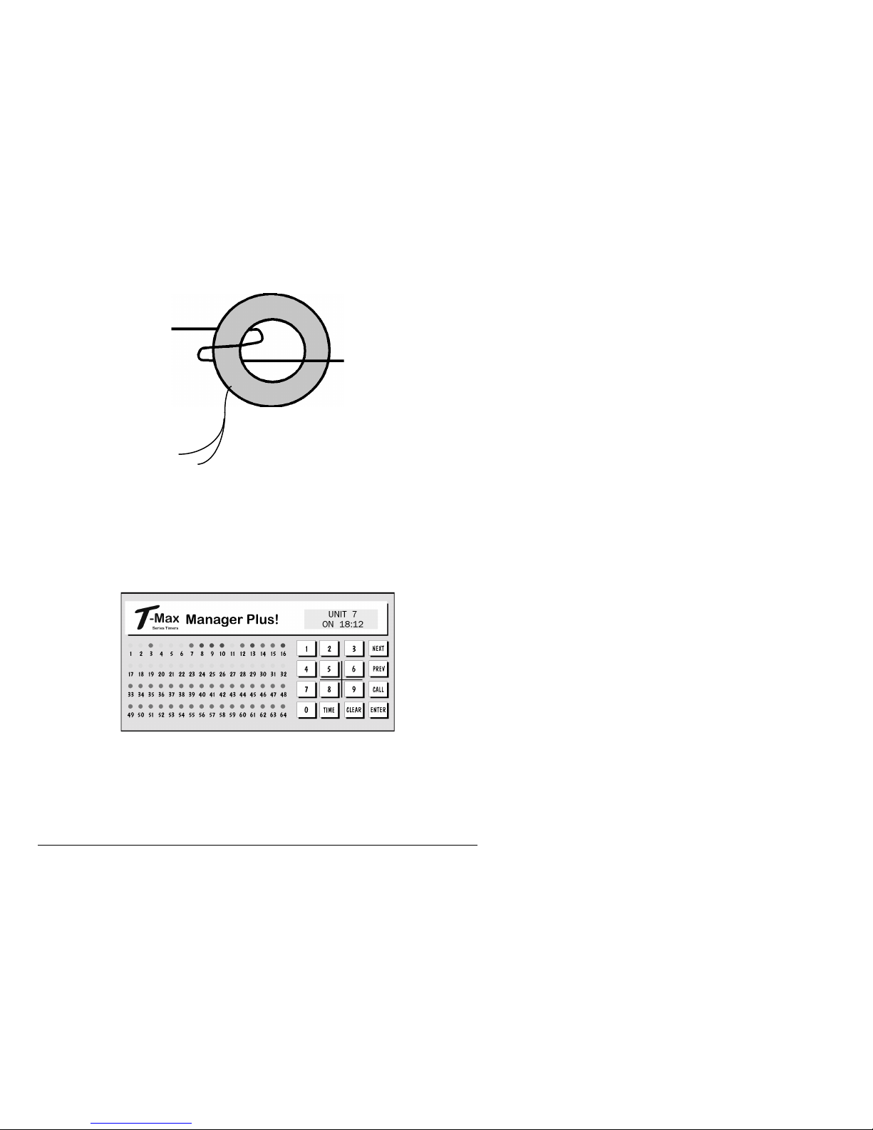
T-Max® Manager/Plus and T-Max®3A/F/I User’s Guide Page 42
12.6 Figure F - Connecting To Lower Current Beds
For beds that pull less than 10 AMPS, wrap the wire around the T-Max® Sentry™ one time.
The T-Max® Sentry™
12.7 Figure G - The T-Max® Mgr/Plus
Front View of the T-Max® Mgr/Plus

T-Max® Manager/Plus and T-Max®3A/F/I User’s Guide Page 43
12.8 Figure H - Rear View Of T-Max® Manager/Plus
T-Max® Mgr/Plus PCB
Jumper On Jumper Off Jumper Off
Jumper Positions for J1 and J2 Jumpers
DB9F RS232 Port
LCD PCB
Z80
Battery
Ribbon Cable
75176
RJ-22 Port
Power
Jumper JP1 and JP2:
On is Master, Off if
Slave
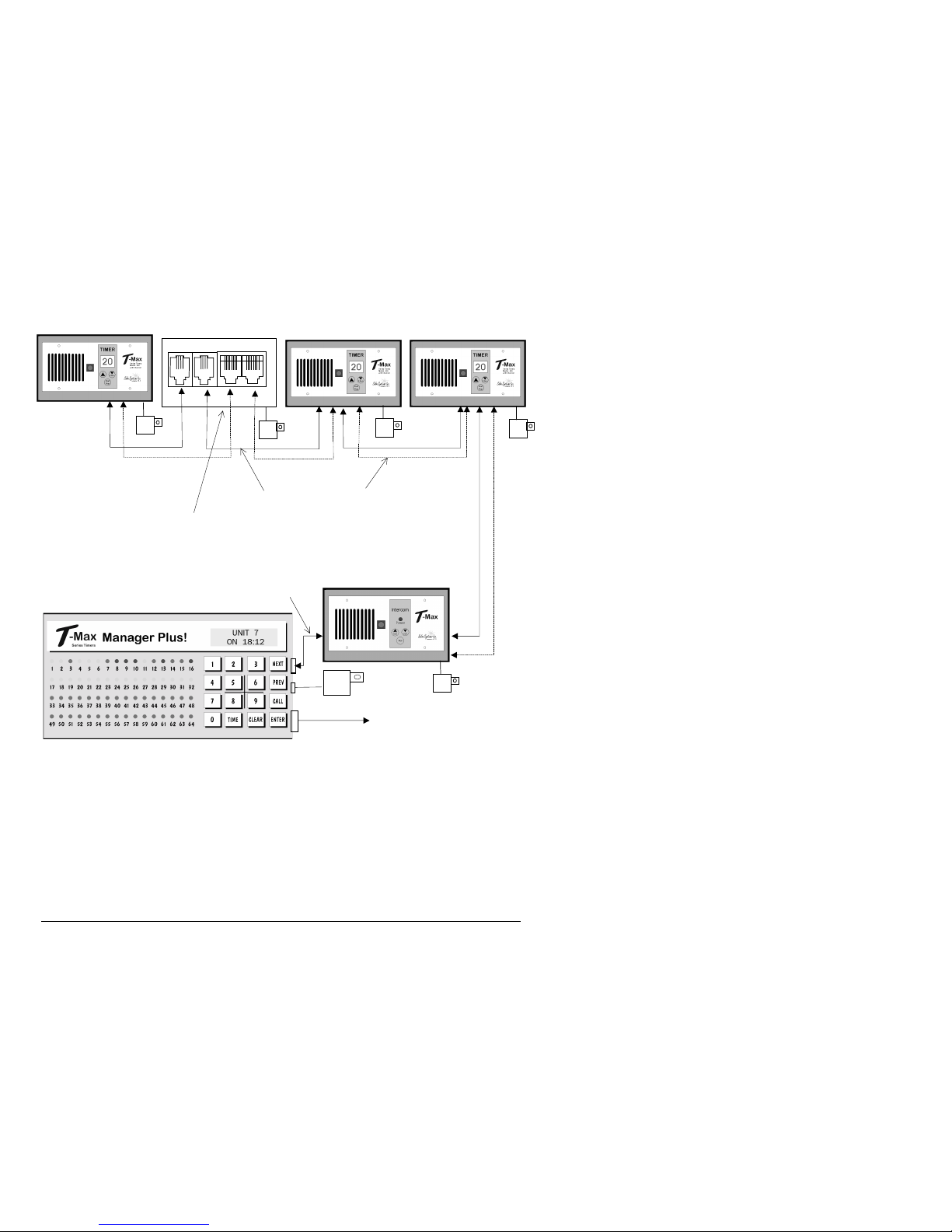
T-Max® Manager/Plus and T-Max®3A/F/I User’s Guide Page 44
12.9 Figure I - Connecting The T-Max® Series
T-Max®3A/F/I Room64 ADNET-Repeater™ T-Max®3A/F/I Room2 T-Max®3A/F/I Room1
RJ-22 and RJ-45 Modular Cables Link Each Room.
2 T-Max® Mgr/Plus’s can be connected to control up to 128 beds!
Connecting the T-Max® Series is Easier than ever!
RJ-22 Modular
Cable Connector
To Computer
9VAC
120VAC
If you are installing more than 20
T-Max®3A/F/Is, you may need
an ADNET-Repeater™
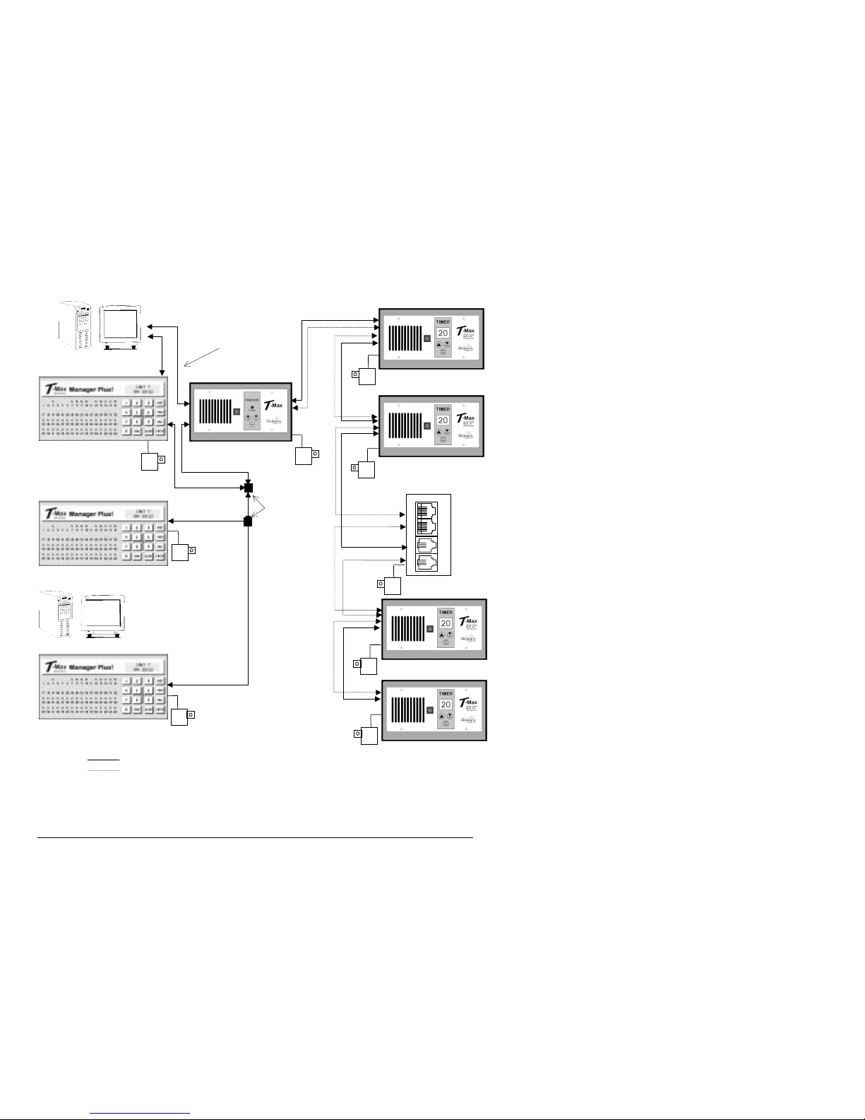
T-Max® Manager/Plus and T-Max®3A/F/I User’s Guide Page 45
12.10 Figure J - Multiple Configurations
Optional Computer
Up to
Optional Computer 128 Beds!
Connect Multiple T-Max® Mgr/Plus’s, Computers, and up to 128 Beds!
T-Max® Mgr/Plus
T-Max® Mgr/Plus (Slave 1)
T-Max® Mgr/Plus (Slave 7)
Room 128
Room 64
Room 2
T-Max®
Slave Kits
Up to 8 T-Max®
Mgr/Plus can be
connected in a single
salon.
Room 1
T-Max® 3A/I/Mstr
ADNETRepeater™
Legend: Modular Cables w/RJ-22 Connectors
Modular Cables w/RJ-45 Connectors
Audio input for inroom automated
messages

T-Max® Manager/Plus and T-Max®3A/F/I User’s Guide Page 46
12.11 Figure K - Modular Cable Pinouts
RJ-22 Connector Untwisted Modular Cable RJ-22 Connector
Use this diagram if you are making your own cables
Important!!!
Salon Systems, Inc. highly recommends that you do not modify the cables provided with each T-Max®3A/F/I. If you need
longer cables, contact your dealer or Salon Systems, Inc. All cables are pre-tested at the factory for proper connection. If
you are not careful in making your own cables, the system may not work properly!
12.12 Figure L - Example Of An External Push Button Circuit
The T-Max®3A/F/I can be ordered with an external push button option. When 5 or 12Volts is applied to the External Start
input on the T-Max®3A/F/I while it is in Delay, the bed will be energized with out having to press the Start/Stop button.
Above is an example of an push button circuit.
To Ext. Start on
T-Max®3A/F/I
5 or 24VAC Out
External Push Button
120VAC
RJ-45 Connector Untwisted Modular Cable RJ-45

T-Max® Manager/Plus and T-Max®3A/F/I User’s Guide Page 47
13. TROUBLE SHOOTING
The T-Max® Series h as been designed for years of trouble free service. However, if a problem does arise, please follow the
following trouble shooting steps before calling technical support.
13.1 Trouble Shooting.
1) No Lights Illuminated on the T-Max® Mgr/Plus
Make sure that the transformer in plugged into the wall and into the power input on the T-Max® Mgr/Plus. Try plugging
the T-Max® Mgr/Plus into a different outlet. If you are using a surge suppresser or UPS backup system, try plugging the
T-Max® Mgr/Plus directly into the wall outlet. Check the circuit breaker in your building to make sure it’s on. Use a
voltmeter to measure t he voltage on the transformer on th e end that connects to the T-Max® Mgr/Plus.
2) The T-Max® Mgr/Plus does not show any beds, and the LCD display shows a black line along the top.
This is an indication the program loaded in the T-Max® Mgr/Plus is lost or has been corrupted. Run ADNET 2000™. Go
to Section 6.3.7 and load the T-Max® Mgr/Plus with new software.
3) The T-Max® Mgr/Plus does not se e any beds.
Go through the Quick installation setup in Section 2. Cycle power on the T-Max® Mgr/Plus. The T-Max® Mgr/Plus will
rescan the network. Make sure each T-Max®3A/F/I has a unique address. Swap the modular cable between the T-Max®
Mgr/Plus and the T-Max®3A/F/I is connected to.
4) When going through the Quick Installation set-up, when I press 888 then Enter on the T-Max® Mgr/Plus to set
the addresses, some or all of the T-Max®3A/F/Is do not go to 99 and buzz.
Remove the terminator from the last T-Max®3A/F/I in the line. Check the cable between the T-Max® Mgr/Plus and the
first T-Max®3A/F/I. Swap the T-Max®3A/F/I in the first room with the last one.
5) When power is applied to the T-Max® Mgr/Plus, bed 1-5 show on the T-Max® Mgr/Plus, but the rest of my beds
do not show.
Go through the Quick Installation in Section 2. Make sure that power is applied and modular cables are connected to each
T-Max®3A/F/I. Try a new modular cable between the last T-Max®3A/F/I displayed and the first T-Max®3A/F/I that does
not show on the T-Max® Mgr/Plus in the daisy chain. If you don’t
have a spare cable, swap the cable between the last TMax®3A/F/I that appears on the T-Max® Mgr/Plus and the first T-Max®3A/F/I that does not appear on the T-Max®
Mgr/Plus with a modular cable that is connected between two T-Max®3A/F/Is that appear on the T-Max® Mgr/Plus
display. If the problem follows, the modular cable is either bad or wired incorrectly. Check the modular cable pinouts on
the defective cable (refer to Section 12.11, Figure K). If the problem does not follow, swap the first T-Max®3A/F/I that
does not appear on the T-Max® Mgr/Plus in the daisy chain with one that does. If the problem follows, return the
defective T-Max®3A/F/I for repair. If the problem does not follow, swap the last T-Max®3A/F/I that appears on the TMax® Mgr/Plus with on e of the other T-Max®3A/F/Is that appears on the T-Max® Mgr/Plus.
6) The Slave T-Max® Mgr/Plus do es not show any beds.
Check and make sure the modular cable is connected to the Slave T-Max® Mgr/Plus. Recycle power to the Master TMax® Mgr/Plus. Cycle power to the Slave T-Max® Mgr/Plus then cycle power to the Master T-Max® Mgr/Plus.
7) How do I make the T-Max®3A/F/Is work as stand-alone timers?
Remove power from the T-Max® Mgr/Plus. Unplug power from each T-Max®3A/F/I, wait 5 seconds, then plug them
back in. On the T-Max®3A/F/I, press the Set button to set time, then press the Start/Stop button to start the session. Power
to the T-Max® Mgr/Plus must stay off while the T-Max®3A/F/Is are being used as independent timers.
8) When I start a session manually, the session time will not start.
Press the Call/Menu button. The following message will appear: SECURITY/CALL. Enter your security number for
security level 1 (See the enclosed Security Level Sheet). An Aster isk (*) will appear on the lower left corner of the LCD
display. You can then start sessions manually.

T-Max® Manager/Plus and T-Max®3A/F/I User’s Guide Page 48
9) I can start sessions from the Master T-Max® Mgr/Plus, but not the Slave T-Max® Mgr/Plus
Enter Security Level 1 (See your enclosed Security Sheet). An Asterisk (*) will be displayed on the lower left corner of the
T-Max® Mgr/Plus. Cycle power to both the Slave T-Max® Mgr/Plus then the Master T-Max® Mgr/Plus. Watch the LCD
display. On the lower right, make sure the display shows “VER-202/T” or higher. If it does not contact your dealer for the
latest T-Max® Series Utility Software and load it into the T-Max® Mgr/Plus as described in Section 6. Check and make
sure the modular cable is connected to the Slave T-Max® Mgr/Plus. Recycle power to the Master T-Max® Mgr/Plus. Go
into the Master T-Max® Mgr/Plus parameter mode (Security Level 3) and set the Max Slave Number to 7. Cycle power to
the Slave T-Max® Mgr/Plus then cycle power to the Master T-Max® Mgr/Plus.
10) When checking my bulb hours (or any other parameter), the value shows 65535 for all beds. Why?
This is an indication that you are trying to check parameters from a Slave T-Max® Mgr/Plus. You can only check and
change parameters from a Master T-Max® Mgr/Plus. To determine if the T-Max® Mgr/Plus is a master or slave, cycle
power to the T-Max® Mgr/Plus and watch the LCD display. The top line will read “TESTING MEMORY #”. If the # is a
number other than a 0 (1-7), then this T-Max® Mgr/Plus is a slave. The T-Max® Mgr/Plus that reads “TESTING
MEMORY 0” is the master.
11) When a session ends, I get 2 periods on the display on the T-Max® 3A/F/I. Why?
This is the clean room indication letting you know that the room needs to be cleaned. Press and hold the Up button on the
T-Max® 3A/F/I until the periods go away and a 0 appears.

T-Max® Manager/Plus and T-Max®3A/F/I User’s Guide Page 49
13.2 Error Codes
Error codes have been incorporated in the T-Max®3A/F/I and the T-Max® Mgr/Plus to aid in troubleshooting.
Error
T-
Max®3A/F/I
Codes
T-Max® Mgr/Plus
Description Possible Solution
N/A E0 Unrecognized
Parameter
Load the T-Max® Manager/Plus with the newest version of
software.
91 E1 EEPROM Error
- On power up,
detects error.
1) Cycle power on T-Max® Mgr/Plus
2) Check parameters on T-Max®3A/F/I.
3) If error occurs repeatedly, return T-Max®3A/F/I for
service.
92 E2 Current Sense
Error - Current
Off
Session has started
but bed is off.
Check to see if bed is off or illuminates momentarily.
If bed is off
1) Check power to bed.
2) Check outlet bed is plugged into.
3) Check circuit breaker
4) Swap T-Max®3A/F/I with one that is working.
If bed illuminates momentary:
1) Make sure T-Max® Sentry™ is connected properly (refer
to T-Max®3A/F/I User’s Guide).
2) Have electrician check beds current draw. If the bed draws
less than 10AMPS, wire from the bed needs to be wrapped
around the T-Max® Sentry™ one time. Refer to TMax®3A/F/I User’s Guide.
93 E3 Current Sense
Error - Current
On
Session has
expired but bed
remains on.
Check to see if bed is on or off. If bed is on:
1) Swap T-Max®3A/F/I with one that is working properly.
2) Check bed for proper operation.
If bed is off
1) Have electrician check the current draw on bed. If fans
drawing <5AMPS, wrap wire from bed around the T-Max®
Sentry™ one time. Refer to T-Max®3A/F/I User’s Guide.
94 E4 Max Time Error
- T-Max®3A/F/I
reporting wrong
Max time.
1) Check the delay on the T-Max®3A/F/I. Make sure the
Delay not set to 55.
2) Replace the T-Max®3A/F/I.
N/A E6 Checksum Error
- T-Max®
Mgr/Plus received
bad value from TMax®3A/F/I
1) Cycle power on the T-Max® Mgr/Plus and T-Max®3A/F/I.
2) Make sure a terminator is connected to the last TMax®3A/F/I in the T-Max® network.
3) Swap the T-Max®3A/F/I with one that is operating
correctly.
N/A E7 Time Out Error -
The T-Max®
Mgr/Plus did not
receive the correct
information from
the T-Max®3A/F/I
1) Make sure 9VAC @ 200mA transformer powering TMax®3A/F/I is plugged in to 120VAC outlet.
2) Make sure a terminator is connected to the last TMax®3A/F/I in the network.
3) Swap transformer with one that is working.
4) Check modular cable to make sure it has not been
disconnected. Replace modular cable.
5) Swap T-Max®3A/F/I with one that is working.

T-Max® Manager/Plus and T-Max®3A/F/I User’s Guide Page 50
14. Index
Adding Beds, 32
ADNET 2000™
Auto Start, 17
Canceling a Session, 19
Com Port Selection, 16
Comms Status Screen, 17
Creating a Shortcut, 13
Delay, 17
Getting and Changing Parameters, 20
Infinite Delay, 17
Installing, 13
Loading New Software into the T-Max®
Mgr/Plus, 22
Manager Utilities, 21
Recording In-Room Messages, 26
Running, 17
Setting Up In-Room Messages, 25
Setting Up T-Max®Mgr/Plus, 22
Starting a Session, 19
ADNET-Repeater™, 3, 32, 44
Auto Addressing
See Quick Installation.
Auto Start
Manual Setup, 8
Using ADNET 2000™, 17
Bed Status, 12
Cable Pinouts
See Modular Cable Pinouts.
Canceling Sessions
Manually, 11
Using ADNET 2000™, 19
Using T-Max® 3A/F/I as an Independent
timer, 35
Clean Room
Clearing, 35
Disabling - See Parameters.
Cool Down Mode, 36
Delay
Manual Setup, 7
Using ADNET 2000™, 17
Emergency Call, 31
Error Codes, 49
Expansion
Adding T-Max® 3A/F/Is, 32
Adding T-Max® Mgr/Plus’, 32
External Push Button Option, 37, 46
Hanging Up the Intercom, 31
Installation
ADNET 2000™, 13
Quick Installation, 4
T-Max® 3A/F/Is, 6
T-Max® 3A/I/Masters, 6
T-Max® Mgr/Plus, 6
Intercom
Adjusting the Volume on the T-Max
3A/F/I, 5
Adjusting the Volume on the T-Max®
3A/I/Master, 30
Auto Shutoff, 31
Call Waiting, 31
Calling a Room from the Front Desk, 30
Calling the front desk from the T-Max®
3A/F/I, 30
Emergency Call, 31
Hanging Up, 31
Recording In-Room Messages, 26
Setting Up, 5, 30
Setting Up ADNET 2000™, 23
Setting Up In-Room Messages, 25
Using, 30
Jumpers
T-Max® 3A/F/I, 40, 41
T-Max® Manager/Plus, 43
Loading New Software into the T-Max®
Mgr/Plus, 22
Maximum Bed Number
ADNET 2000™, 22
Manual Setup, 8
Modular Cable Pinouts, 46
Parameters
Changing and Getting Manually, 8
Getting and Changing Using ADNET
2000™, 20
Table, 10
Pausing a Session, 11, 35

T-Max® Manager/Plus and T-Max®3A/F/I User’s Guide Page 2
Quick Installation, 4
Rescan
ADNET 2000™, 23
Security Numbers, 10
Specifications, 3
Starting Sessions
Manually, 11
Using ADNET 2000™, 19
T-Max® 3A/F/I
Adding, 32
Canceling Session, 35
Circuit Board Connections, 40
Components, 2
Connecting to tanning bed, 4
Diagram, 39
Enclosure, 3, 38
External Push Button, 37, 46
Manual, 33
Manual Installation, 6
Pausing Session, 35
Setting Delay Manually, 34
Setting Parameters Manually, 33
Setting the Address Manually, 6
Specifications, 3
Using as an Independent timer, 34
T-Max® 3A/I/Master, 39
Components, 2
Manual Installation, 6
Specifications, 3
T-Max® Enclosure, 3, 38
T-Max® Manager/Plus
Adding T-Max® Mangers/Plus’s, 32
Address, 8
Circuit Board, 43
Components, 2
Connecting to a Computer, 6
Diagram, 42
Emergency Call, 31
Going From Computer to Ma nual Control,
11
Hanging Up the Intercom, 31
Manual Installation, 6
Manual Set Up, 7
Setting the Address, 32
Specifications, 3
Starting Sessions Manually, 11
Using the Intercom, 30
T-Max® Monitor, 3, 36
T-Max® Monitor/Plus, 3, 36
T-Max® Sentry™, 3, 36, 41
T-Max® Slave Kit, 3, 32
T-Max® Speaker, 3, 37
Trouble-Shooting, 47
Wiring, 4, 5, 44, 45
 Loading...