

Salicru SLC TWIN PRO series, UPS SLC TWIN PRO series User Manual
UNINTERRUPT IB LE P OWER SU PPLY (UPS) + LIGH TIN G FLOW D IM MER S TABILIZ ERS (I LUEST ) + SW ITC H MO DE P OWER S UPPLY + STATIC INVERTERS + PHOTOVO LTAIC INVERTERS + VOLTAGE STABILIZERS AND P OWER L IN E CO ND ITI O NERS
UPS SL C TWIN PR O seri es
0. 7 t o 3 kVA
USER’S MANUAL
UNINTERRUPTIBLE POWER SUPPLY

3
SALICRU
General index
1. Introduction.
1. 1 . Acknowledgement letter .
1.2. Using this manual.
1.2.1 . Conventions and us ed symbols.
1.2.2. For more information and/or help.
1.2.3. Safety instructions.
1.2.3. 1 . General safety warnings.
1.2.3.2. To keep in mind.
1.2.3.3. Safety wa rning regarding batteries.
2. Quality and standard guarantee.
2.1. Declaration of the management.
2.2. Standard.
2.3. Environment.
3. Presentation.
3.1. Views.
3.1 .1 . Views of the equipment.
3.2. Definition of the product.
3.2.1. Nomenclature.
3.3. Operating principle.
3.3.1 . Main features.
3.4. Options.
3.4.1 . Isolation transformer.
3.4.2. External maintenance manual bypass.
3.4.3. Integration in IT networks by means of the SNMP adaptor.
3.4.4. Relays interface card.
3.4.5. MODBUS protocol.
4. Installation.
4.1. T o be considered in the installation.
4.2. Reception of the equipment.
4.2.1. Unpacking, content checking and inspection.
4.2.2. Storage.
4.2.3. Unpacking.
4.2.4. T ransport to location.
4.3. Connection.
4.3.1 . Connection of input .
4.3.2. Connection to output.
4.3.3. Connection of external batteries (extended back up times) -B1-.
4.3.4. Connection of main input earth terminal ( ) and the earth bonding
terminal
( ).
4.3.5. Terminals for EPO (Emergency Power Off).
4.3.6. Communication ports.
4.3.6.1 . USB interface.
4.3.6.2. Protection a gainst tr ansien t voltage s for Mod em / ADSL / Fax / ...
lines.
4.3.6.3. Smart slot.
4.3.6.4. Relays interface (option).
4.3.7. Software.
4.3.8. Considerations before starting up the connected loads.
5. Operating.
5.1. UPS commissioning and shutdown.
5. 1 . 1. Preliminary controls.
5.1 .2. Start up the UPS, with AC mains.
5.1 .3. Start up the UPS, with no AC mains (Battery mode)
5.1 .4. UPS shutdown with AC mains (on Inverter mode).
5.1 .5. UPS shutdown with no AC mains (on Battery mode).
5.1 .6. Battery test function.
5.1 . 7 . Alarm silencer.
5. 1 .8. EPO (Eme rgency Power Output) .
6. Control panel with LCD.
6.1 . Control panel.
6.2. Setting and configuration of the control panel.
6.2.1. No output mode, code «0».
6.2.2. Bypass mode , code «1 » .
6.2.3. Line mode.
6.2.4. Battery mode / Battery test mode.
6.2.5. Wrong mode.
6.2.6. ECO mode (Economy).
6.2.7. Converter mode.
6.3. Settings through the LCD panel of the synoptic.
7 . Maintenance, warranty and service.
7.1 . Battery maintenance.
7 .1 .1 . Notes for installing and replacing the batteries.
7.2. UPS T rouble Shooting guide.
7 .2.1. T roubleshooting guide. Warning indications.
7 .3. W arranty conditions.
7 .3. 1 . Covered product.
7 .3.2. Warranty terms.
7 .3.3. Out of scope of supply.
7.4. Description of the available maintenance and service
contracts.
7 .5. Techn ical service netw ork.
8. Annexes.
8.1 . General technical specifications.
8.2. Glossary.
4
SALICRU
1. Introduction.
1.1. Acknowled gement letter.
We would like to thank you in advance for t he trust you have
placed in us by purc hasing this produc t. Read this instruct ion
manual carefully before starting up the equipment and keep it for
any possible future consult that can arise.
We remain at you entire dispo sal for any fur ther i nformati on or
any query you should wish to make.
Yours sincerely.
The equipment here described can cause important
physical damages due to wrong handling. This is
why, the installation, maintenance and/or fixing of the
here describ ed e qui pme nt must b e do ne by our st af f or
specifically authorised.
According to our policy of constant evolution, we reserve
the right to mo dify the specif ications in part or i n
whole without forewarning.
All reproduction or third party concession of this
manual is prohibited without the previous written authorization of our firm.
1.2. Using this manual.
The target of this manual or p u b l ication is to p r o v i d e i n f o r m a t i on
reg ardi ng th e safe ty a nd to give explanations abo ut th e procedures for the installation and ope rating of the e quipme nt. This
manual and r e st of s uppo rt d o c umentatio n has to be read carefully before installing, location change, setting or any handling of
any kind, including the start up and shutdown operation.
Keep this document for future consults.
In the next pages, t he “equipment” and “ S.T.S.” terms, are re-
ferred to the Uninterr uptibl e Power Supply or UPS an d Ser vic e
and Technical Support respectively.
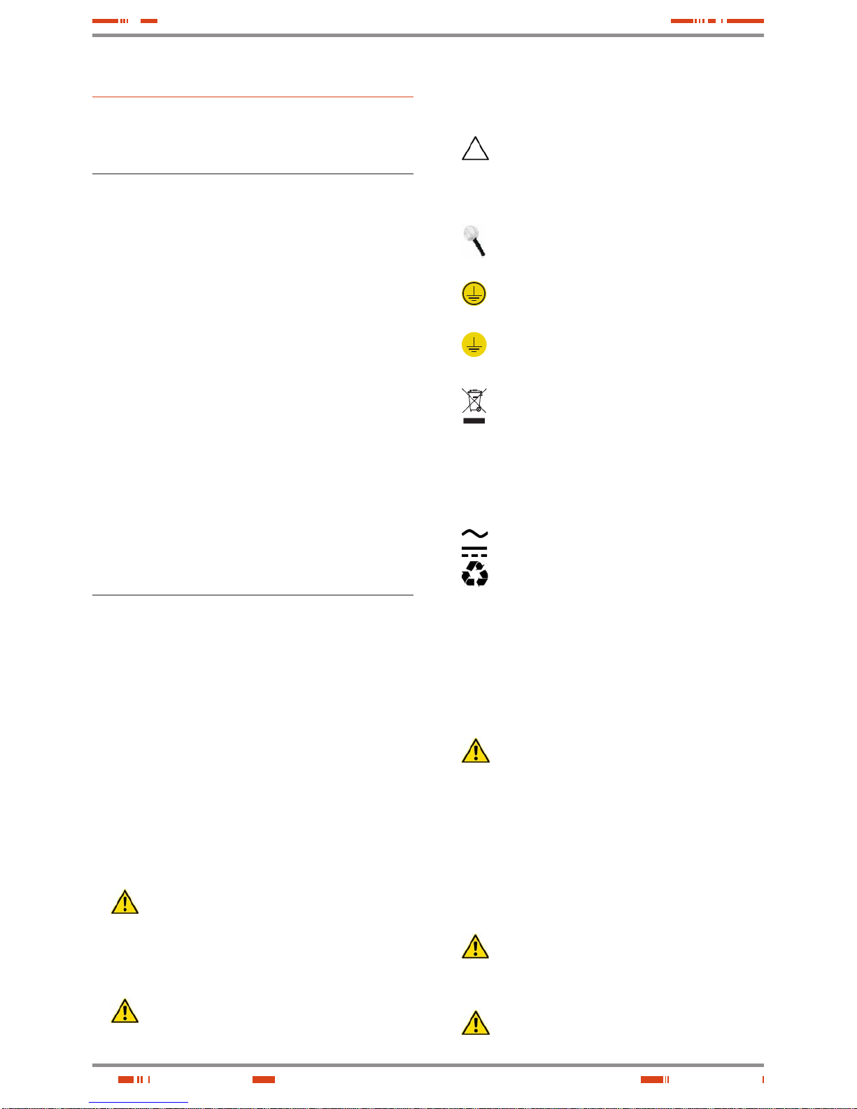
1.2.1. Conventions and used symbols.
Some or all the sym b ols of this sectio n can be used and shown
in the equipment and/or in the description of this document. It is
advisable to be familiar with them and understand their meaning.
•
«Danger of electrical discharge» symbol. Pay spe-
cial attentio n to i t , b ot h i n t h e i n d i cation on the equipment and in the paragr aph referred to this user’s manual,
because it contents features and basic informations for
person safet y. To not respect these indic atio ns c an resu lt in
serious incidents or even the death due to electrical discharges
•
«Warning» symbol. Carefully read the indicated par-
agraph and take the stated prevention measures, so it
contents basic safety instructions for persons. To not respect
such instructions can cause serious incidents. Those indications with “CAUTION ” symbol content features and basic instructions for safety of the things. To not respect such
instructions can damage the goods.
•
«Precaution» symbol. Read the paragraph tex t and
take the stated preventive me diums, it contents the
basic instru ctio ns and features for t he equip ment safet y. To
not respect t hese indicat ions can create materia l damages
on the own equipment, installation or loads.
•
«Notes of information» symbol. Additional topics that
complement the basic procedures. These instructions
are import ant for the equi pment use and it s optimum
efficiency.
•
«Main protective earthing terminal» symbol. Connect the earth cable coming from the installation to this
terminal.
•
«Earth bonding terminal». Connect the earth cable
coming from t h e l oad and the external bat tery cabinet to
this terminal.
•
Preservation of the environment: The presence of
this symbol in the product or in their associated docu-
mentation states that, when its useful life is expired, it
will not be dispo s e d tog et he r wi t h th e d o me st i c re si d u al s. In
order to avoid possi ble damag es to the envir onment , separate this produc t fr om ot her re si du als an d re cyc le i t sui ta bl y.
The users can contact with their provider or with the pertinent
local author iti es to be info rme d on how an d where t hey can
take the product to be recycled and/or disposed correctly.
•
Alternating Current A.C..
• Direct Current D.C..
• Recycle.
1.2.2. For more information and/or help.
For more information a nd/or help of your speci fic unit, contac t
with our Service and Technical Support (S.T.S.).
1.2.3. Safety instructions.
• Check the data of th e name pl ate are the re quir ed by th e in stallation.
•
Never forget that the UP S is a generator of ele ctrical energy , therefore the user has to take precau-
tions about against direct and indirect contacts.
Its energy sour ce, a part from the AC mains, lies on th e batteries, usually in clude d in the sam e case or c abinet th at the
equipment electronics. However, some models and/or extended back up times, batteries can be supplied in a separate
case or cabinet.
If the batteries are connected to the equipment and their protections are switched “On”, whenever they are, it is irrelevant
if the UPS is or not connected to mains, as well as the status
of the mains protec tion. The ou tlets or out put power blo cks
will supply voltage meanwhile the battery set has energy.
•
Compliance as regards to “Safety instructions“ is
mandator y, being the us er the leg al respo nsible
regarding to its observance and application. Read them care-
fully and follow the stated steps in the established order, keep
them for future consults that may arise.
•
If the ins tr uc tio ns a re n ot in to ta l or p ar t ia l an d in
special referred to the safety, do not carry on with
USER MANUAL
5
SALICRU
the installation or commissioning tasks, because there
could be a risk on you r s a f e ty or on the oth e r/s p e rsons,
being able to make se r io u s i n ju ries even the dea t h, al s o i t
can cause damages to the equipment and/or to the loads
and installation.
•
The local ele ctrical regulatio ns and the different re -
strictio ns o f th e c li ent’s site, they can invalidate some
recommendations included in the manuals. When discrepancies exist, the user has to comply the local regulations.
•
The equipment s provided wit h power cord with plu g
and outlets, can be connected and used by personnel
without any kind of experience.
The equipment s w it h power b lo c ks have to be i ns t al le d by
qualified personnel and it ca n be used by perso nnel with
not specific training, just with only help of this manual.
A person is defi ned as qualified, if it has experien ce of as sembling, commissioning and perfect control operating of
the equipmen t, if h e has t he re qu irem ent s to do t he j ob an d
if has read and under stand all the thing s described in t his
manual, in particular the safety indications. Such preparation
is considered only valid if it is certified by our S.T.S..
• Place the equipme nt the closest to the power supply an d
loads to be supplied, leaving an easy access if it were needed
an urgent disconnection.
In the hard wired eq u i p m e nts and due to the impos sibility of
fast discon ne ct io n, a di c onn ec t io n devi c e (switch) with easy
access and close to the equipment will be installed.
• Warning labels should be placed on all primary power
switches installed in places away from the equipment to alert
the electr ical maintenance per sonnel of the presenc e of a
UPS in the circuit
The label will bear the following text or an equivalent one:
Before working in this circuit.
• Isolate the Uninterruptible Power System (UPS).
• Check the voltage between all terminals including the
protective earth.
Risk of voltage feedback from UPS.
1.2.3.1. General safety warnings.
• All connect ions and discon nections of the c ables from the
equipment, in cludin g the contr ol ones, will b e done with n o
power supply and the switches on rest, position «O» or «Off».
• Shutdown the equi pment co mpletely by switc hing «Of f» the
button of the c ontrol panel first. Nex t disconnect t he cable
from the wall outlet for equipments up to standard 3 kVA or by
switching «Off» the input circuit breaker of the installation and
disconnect the power supply cables in models of the 3 kV A B1
or higher power rate.
The indiscriminate manoeuvring of the switches may
involve production losses and/or equipment dam-
ages. Consult the documentation before doing any action
•
Pay special attention to the labelling of the equipment
that warns about the «Electrical shock hazard». Inside
the equipment there are dangerous voltages, never open the
enclosure, the ac cess has to be do ne by qualified staf f. In
case of maintenance or fault, consult to the closest (S.T.S.).
• Cross cable sections used to supply the equipment and loads,
will be according to the nominal current stated in the nameplate
label of the equipment, and respecting the Low Voltage Electrotechnical Regulations or standards of the country.
Use approved cables only
•
Protection Ear th c able of t he UPS drives t he leak age
current of the load devices. An isolated earth cable has
to be installed a s part of t he circui t that suppli es the equi pment. Cross ca ble secti on and its features w ill be same as
the power supply cables, but with green colour with or without
the yellow strip.
All outlets of th e UPS has an earth bonding, d uly c o nne c ted
and those equipments with power blocks there is an exclusive
terminal for the load earth connection. When an outgoing distribution is done, i.e power strips, it is essential that they have
an earth terminal connected to each one of them.
It is essential that the cables that supplies the loads have the
earth connection cable.
The protectio n earth must be conn e c te d to th e fr am e
or metallic chassis of any electrical equipment (in our
case to the UPS, battery cabinet or case and loads), assuring
that it is done before connecting the input voltage.
Check the qual ity and availabili ty of the ear th, it has to be
between the defined parameters by the local or national
regulations.
• For the smallest devic es (the o nes c onn ec ted wi th th e fore seen power cord wi th plug), the user has to chec k the wall
outlet corres p o n d s w i t h t he type of supplie d pl u g, w it h e arth
duly installed and connected to the local protection earth.
•
During the normal UPS operation, in equipments up to
3kVA the power cord cable can’t be disconnected
from wall outlet, because the protection earth of the own UPS
would be disco nnected and also the ear th from the loads
connected to the output.
For this reason, th e general protection ear th cable of the
building or switc hgear panel t hat supplies t he UPS will not
be disconnected.
• In small equipments (the ones connected with the foreseen
power cord with plug), check that the sum of the leakage currents
of the UPS and connected load/s do not exceed over 3,5mA.
• The installation w ill have input protecti ons sized to the currents of the equipment and stated in the nameplate label
(RCD devices ty pe B and cir cuit br eakers wit h C chara cteristic or any other equivalent one).
Overload cond ition s are consi dered as a no nperm anent an
exceptional oper ating mode, so these currents wil l not be
kept in mind when sizing the protections.
• Do not overload the UPS by conne cting loads with inr ush
consumptions at its output, like laser printers.
• Output protection will be done with a circuit breaker of C characteristic or an equivalent one.
It is recomme nded to distribute t he output power, into four
lines as minimum. Eac h one of them wil l have a protection
circuit breaker sized to the quarter of the nominal power.
This kind of outg oing dis tribu tions w ill allow th at any fault in
any device connected to the equipment, that makes a shortcircuit, wil l affect to the line wi th the faulty devic e only. An
uninterruptible power supply will be guaranteed to the rest of
connected loads, due to the protection tripping of the affected
line by the short-circuit only.
• When replacing a fuse, do it for another of the same type, characteristics format and size.
• Under any concept the input power cord will be connected to the
output of the equipment, either directly or through other ways.
• All the equipmen ts have an auxiliar y terminal str ip to install
an external emergency power off button (EPO) , and it will belong to the user property.
Type of circui t is selectable throu gh the LCD panel of the
equipment. T he contact is preset fro m factory as norm ally
6
open, so the button must be switched to close the circuit and
the voltage to the l oads is broken. To establish the power
supply to the load s again, the EPO butto n must be deacti vated.
EPO doesn’t affe ct to the power sup ply of the equ ipment, it
only breaks the power supply to the loads as a safety measure.
•
When supplying input voltage to a UPS with static by-
pass, although the inverter is still tur ned «Off» (deactivated) it doesn’t m ean that at the output ther e will not be
voltage.
So, to do it, the input switch will have to be turned «Off».
Put warnings of dang er and/or emergency switches if t he
safety Standards require it in your particular installation.
• All power supply electrical cables have to be fixed to the
equipments an d l oad s, in terfaces, etc..., to unmovable parts
and in the way to avoid treads, tri ps on them or fortuito us
pulls.
• CHASSIS or RACK mounted equipments are destined to be installed in a predetermined set to be done by professionals.
The installation has to be designed and executed by qual-
ified perso nnel, who w ill be th e respo nsib le to app ly the
safety and EMC reg ulati ons an d st and ard s that c ont rol s
the particular installations where the product is destined.
The equipments assembled in CHASSIS do not have
enclosure prote ction, even th e power block s are unpro tected.
Some RACK mounted equipments do not have the power
blocks protected.
• Never manipulate the equipment with wet hands.
1.2.3.2. T o keep in mind.
• Do not try to dismantle or change any part of the
equipment, if t his action is not contem plated in this
document. Manipulation inside the UPS due to any modification, reparatio n or any other cause, can make an el ectric al
discharge of high voltage and it is restricted to qualified staff
only. Do not open the equipment.
A part from the implicit stated risks, any action that make the
modification, internal or external of the equipment or just only
the simple inter vent ion in side of i tsel f, which i s not stated i n
this document, it can expire the warranty.
• If it is obser ved that the UPS exhaust s smoke or toxic gas,
shutdown it imme diately and disconne ct it from the power
supply. This kind of fault can cause fire or electrical discharge. Contact with our (S.T.S.).
• In case of an accid en t al eq ui p me nt dr o p pin g or i f th e en c l osure is damaged, d o not st ar t it u p und er any con ce pt. Th is
kind of fault can c ause fire or electr ical dischar ge. Contact
with our (S.T.S.).
• Do not cut, manipulate the electrical cables, do not put heavy
objects over the m too. Any of these actio ns could caus e a
short-circuit and make a fire or electrical discharge.
Check that the electrical cables of connection, plugs and outlets are in good conditions.
• When moving an equipment from a cold place to a warm environment and vice versa, it can cause condensation (small
water drops) in the external and i n ternal surfaces. Before installing a moved equipment from another place or even packaged, the equip ment will be lef t for a minimum time of t wo
hours in the new location before making any action, with the
purpose of adapting it to the new environmental conditions
and avoid the possible condensations.
The UPS has to be completely dry before starting any installation task.
• Do not store, install or expos e the equipment in co rrosive,
wets, dusty inflammable or explosive environments and
never outdoors.
• Avoid to locate, install or store the equipment in a place with
direct sunlight or high temperatures. Batteries could be damaged.
In the exceptional c ase an d lon g expos itio n to intens e heat,
batteries can cause filtrations, overheating or explosions,
which can c ause fire s, burn or ot her inj uries. H igh tem peratures can also make deformation in the plastic enclosure.
• The location wi ll be spac ious, air y, away from heat sources
and easy access.
• Do not obstruct the cooling grids by entering objects through
themselves or other orifices.
•
In equ ip m ent s of l ow power r ate (up to 3kVA), leave as minimum space of 25 cm in the equipment peripheral and 50 cm
for higher power rates equipments.
•
Also in the UPS with power bloc ks, it is recommend ed to
leave another additio nal 50 c m for an eventual inter vent ion
of the (S.T.S.), considering that if it means to move the UPS,
the connected cables will have the needed clearance.
• Do not put materials over the equipment or parts that obstruct
the correct visualization of the synoptic.
• Be careful to not wet it, bec ause it i s not waterpr oof. Do not
allow entering any kind of liquids in. If accidentally the outside
of the machine comes into contact with liquids or salt air, dry
it with a soft and absorbent cloth.
• To clean the equip ment, wipe over a damp clot h and then
dry it. Avoid sprinkling or spillage that could enter through the
slots or cooling grids, which may cause fire or electric shock.
Do not clean the e quipme nts with pr oduc ts that co uld have
alcohol, benzene, solvent or other inflammable substances,
or they are abrasive, corrosive, liquids or detergent.
• When it is needed to r em ove the pr ote c ti o n c over to acc e s s
to the terminals, they will have to be put back before starting
up the equipme nt. O ther wis e you may incur p erso nal injur y
or equipment damage.
• Be careful to not lif t heavy loads w ithout hel p, according to
the following recommendations:
, < 18 kg.
, 18 - 32 kg.
, 32 - 55 kg.
, > 55 kg.
• UPSs are electroni c equipmen ts, so they will be tr eated as
they are:
Avoid shocks.
Avoid jolting or bouncing of the UPS, like those produced
by moving the equip ment o n a hand tr uc k and move on
an uneven or wavy surface.
• UPS transport will be done packaged inside its original packaging in order to prevent it fro m shock and impac t and by
means of the suit able ty pe of packaging (car ton box, pallet
packaging, ...) and appropriate to its weight.
• Although the physical location of the elements can differ from
the illustrations in this manual in some cases, the correct labelling correct the possible doubts and makes easy its com-
prehension.
USER MANUAL
7
SALICRU
1.2.3.3. Safety warning regarding batteries.
• The manipulation and connection of the batteries
shall be done and supervised by personnel with
battery knowledge only.
Before doing any action, disconnect the batteries. Check that
no current is pres ent and there is n ot dangerou s voltage in
the DC BUS (capacitors) or in the endpoint of the battery set
terminals.
Battery c ircuit i s not isol ated from inp ut voltag e. Dangerous
voltages can be fo und bet ween the term inals of th e batter y
set and the ear th. Ch ec k t hat th ere is n ot any volt age at t he
input before take any action over them.
• When faulty batteries are replaced, the complete battery set
has to be replace d, less exceptional cases in new equi pments, were due to manuf acturing faults it will onl y be replaced the defective ones.
The replacem ent will be done by anot her one of the same
type, voltage, capacity, quantity and brand. All of them has to
be of the same brand.
• Generally, the used batteries are sealed lead acid of 12V and
maintenance free (VRLA).
• Do not reuse the fault y batteri es. There cou ld be an explo -
sion or burst any bat ter y wit h the involve d probl ems and i ssues that could happen.
• Generally suppl ied batteries are i nstalled in the s ame cab-
inet, case or rack of the equipment. Depending on the power,
autonomy or both, they c an b e su p pl ie d s ep aratel y fr om t h e
equipment in another cabinet, case or rack, with the interlink
cables among them. Do not modify its length.
• In those equipments requested without batteries, their ac-
quisition, installation and connection of themselves will be
done by the end -user and unde r his respons ibility. Data
concerning the batteries as regards to quantity, capacity and
voltage, are stated in thi s battery label sticked be side the
nameplate of the equ ipment. Respect these data, batter y
connection polarity and the supplied circuit diagram strictly.
For an optimum and efficient operating, the battery set has to
be located as close as possible to the equipment.
•
The battery voltage can involve the risk of electric
shock and can produce high short circuit currents. Ob-
serve the following preventive measures bef ore ma nipulating
any terminal block identified in the labelling as «Batteries»:
Disconnect the corresponding protection elements.
When connecting a battery cabinet to the equipment,
respect the cable’s polarity and colour (red-positive;
black-negative) indic ated in the manual and in the c orresponding labelling.
Wear rubber gloves and shoes.
Use tools with insulated handles.
Take off watches, rings or other metal objects.
Do not place metal tools or objects over the batteries.
Never manipulate with your hands or through conducting
objects, d o not shor t eit her the bat tery ter minal bl ock of
the equipment or the own from the batteries.
• In order to avoid a complete d ischarge of th e batteries and
as a safety measure after a long blackout of th e co mm erc ial
mains and when ending the working day, proceed to the load
shutdown and then to the equipment too, by following the operating described in this «User’s manual».
• When the equipm ent and/or battery mo dule has a protec-
tion through a f use and it were needed to be re placed, it will
always be done by another on e with the same dimen sion,
type and size.
• For long periods of d isconnec tion, consi der that the equi pment has to be conn ected once a month for 10 hours as
minimum, in order to charge the batteries, so the irreversible
degradation of itself is avoided. On the other hand, in case of
storing an equipment, it will be done in a fresh and dry place,
never outdoors.
• Never short the bat tery termi nals as it involves a high r isk. It
involves the detriment of the equipment and ba tteries.
• Avoid mechanical efforts and impacts.
• Do not open or mutilate the battery. Spilled electrolyte is
harmful and toxic to the skin and eyes.
• Do not dispose the batteries in a fire and high temperatures.
The batteries may explode.
• In case of contac t of the acid wit h parts of the b ody, wash
immediately wit h plenty water and c all urgentl y the nearest
medical service.
• Batteries involve a seri o us risk for the health and for t he e nvironment. Th eir disposal s hould be done ac cording to the
existing laws.
8
2. Quality and standard
guarantee.
2.1. Declaration of the management.
Our target is the client’s satisfaction, therefore this Management
has decide d to e st a b li s h a Q u ali ty and Environmental p o li c y, by
means of installation a Quality and Environmental Management
System that becomes us capable to comply the requirements
demanded by the standard ISO 9001 and ISO 14001 and by our
Clients and concerned parts too.
Likewise, the enterprise Management is committed with the development and improvement of the Quality and Environmental
Management System, through :
• The communication to all the company about the impor-
tance of satis faction both in the client’s requirements and in
the legal and regulations.
• The Quality and Environmental Policy diffusion and the fixa-
tion of the Quality and Environment targets.
• T o carry out revisions by the Management.
• T o provide the needed resources.
2.2. Standard.
The SLC T WIN PRO product i s designed, manufactur ed and
commercia lized in acc orda nce wit h the st andard E N IS O 90 01
of Quality Management Systems. The
marking shows the
conformit y to the EEC Directi ve by means of the ap plicatio n of
the following standards:
• 2006/95/EC Low voltage directive.
• 2004/108/EC Electromagnetic Compatibility directive
(EMC).
In accordan ce wit h the spe cific ations of t he harmon ized stand ards. Standards as re f ere nce :
• EN-IEC 62040-1. Uninterruptible power supp ly (UPS). Part
1-1: General and safety requirement s for UPS’s used in ac cessible areas by end users..
• EN-IEC 60950-1. IT equipments. Safety. Part 1: General re-
quirements.
• EN-IEC 62040-2. Uninter ruptibl e power supply (UPS). Part
2: EMC requirements.
The manufacturers responsibility is excluded in the event
of any modificati on or interventi on in the produc t by the
customer’s side.
This is a produ ct for its u se in co mmerc ial and in dustr ial
applications, so restrictions and additional measures can
be needed in the installation to prevent perturbations.
Declaration of c onformity CE of t he product is at the c lient
disposal under previous request to our headquarters offices.
2.3. Environment.
This product has been designed to respect the environment
and has been manuf actured in accordanc e with the standard
ISO 14001.
Equipment recycling at the end of its useful life:
Our company co mmit s to use th e ser vi ces of aut hori sed so cie -
ties and according to the regulations, in order to treat the recovered product at the end of its useful life (contact your distributor).
Packaging:
To recycle the packing, follow the legal regulations in force.
Batteries:
The batteries m ean a serious danger for healt h and environ-
ment. The disp osal of them mu st be done in ac cordanc e with
the standards in force.
USER MANUAL
9
SALICRU
3. Presentation.
3.1. Views.
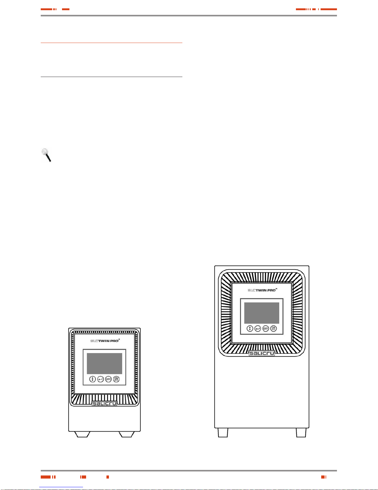
3.1.1. View s of the equipment.
Figures 1 to 6 show the ill u st r ati ons of the equipment according
to the case format an d depending on t he power of the model.
Nevertheles s and due to the c onstant evolu tion of the pr oduct ,
some discre pancies or small contr adictions can ari se. In front
of any doubt, the labelling of the equipment will always prevail.
Figures regard ing its main features or s pecificati ons can
be checked in the nameplate of the equipment. Keep them
in mind for its installation.
Models from 0.7 and 1 kV A Models from 1.5 to 3 kVA
Fig. 1. Front view fr om 0.7 to 3 kVA models.
10
Protection
cover for
smart slot
Output
sockets
Input socket
Input
breaker
protection
Fan
USB
Transient
protection
(*)
EPO
Extended
autonomy
connector
Protection
cover for
smart slot
Output
sockets
Input socket
Input
breaker
protection
Fan
USB
Transient
protection
(*)
EPO
(*) Transient protection (fax, modem,...)
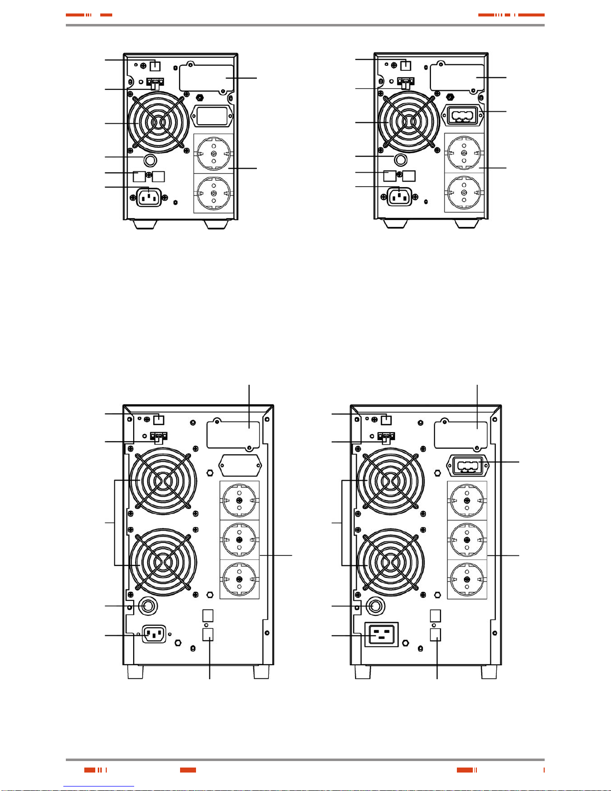
Models from 0.7 and 1 kVA (standard) Models from 0.7 and 1 kVA (B1)
Fig. 2. Rear vi ew fro m 0.7 and 1 kVA.
Protection cover for
smart slot
Output
sockets
Input socket
Input
breaker
protection
Fans
USB
Transient protection ( *)
EPO
Models from 1.5 and 2 kVA (standard) Models from 1.5 and 2 kVA (B1)
(*) Transient protection (fax, modem,...)
Extended
autonomy
connector
Output
sockets
Input socket
Input
breaker
protection
Fans
USB
Transient protection ( *)
EPO
Protection cover for
smart slot
Fig. 3. Rear vi ew fro m 1.5 and 2 kVA.
USER MANUAL
 Loading...