

SALICRU SLC ADAPT Users guide
USER'S MANUAL
UNINTERRUPTIBLE POWER SUPPLY (UPS)
SLC serie ADAPT
180, 300 y 500 kVA

General index
1. INTRODUCTION.
1.1. THANK YOU LETTER.
2. SAFETY INFORMATION.
2.1. USING THIS MANUAL.
2.1.1. Conventions and symbols used.
3. QUALITY ASSURANCE AND STANDARDS.
3.1. STATEMENT BY THE MANAGEMENT.
3.2. STANDARDS.
3.2.1. First and second environment.
3.2.1.1. First environment.
3.2.1.2. Second environment.
3.3. ENVIRONMENT.
4. PRESENTATION.
4.1. VIEWS.
4.1.1. Views of the device.
4.1.2. Device configurations.
4.2. DEFINITION OF THE PRODUCT.
4.2.1. Nomenclature.
4.3. GENERAL DESCRIPTION.
4.3.1. Introduction.
4.3.2. Conceptual diagram of the system.
4.3.2.1. Power modules (PM).
4.3.2.2. Static bypass.
4.3.2.3. Extra charger modules for 180 and 300kVA devices.
4.3.3. UPS operating modes.
4.3.3.1. Normal mode.
4.3.3.2. Battery mode.
4.3.3.3. Bypass mode.
4.3.3.4. Manual Bypass mode (maintenance bypass).
4.3.3.5. Parallel-Redundant mode.
4.3.3.6. ECO mode.
4.3.3.7. Frequency converter mode.
5. INSTALLATION.
5.1. RECEPTION OF THE DEVICE.
5.1.1. Reception, unpacking and contents.
5.1.2. Storage.
5.1.3. Unpacking and transportation to the site.
5.1.3.1. Unpacking the power module.
5.1.4. Siting, immobilising and considerations.
5.1.5. Room for the batteries.
5.2. CABINET POSITIONING.
5.2.1. 180 to 300kVA devices.
5.2.2. 500kVA devices.
5.2.3. Batteries.
5.2.4. Installation of seismic kits (optional).
5.2.5. Installation of power modules.
5.2.6. Installation of extra charger modules.
5.3. CONNECTIONS.
5.3.1. Cable entry for 180 and 300kVA devices.
5.3.2. Cable entry for 500kVA devices.
5.3.3. Connection to the entry.
5.3.3.1. Specifications.
5.3.3.2. Specifications for power cable terminals.
5.3.3.3. Disconnectors.
5.3.3.4. Connection of the power cables.
5.3.4. Control and communication cables.
5.3.4.1. Relay interface.
5.3.4.2. Communications interface.
6. OPERATION.
6.1. STARTUP PROCEDURE.
6.1.1. Startup in Normal mode.
6.1.2. Startup from Battery mode (COLD START function).
6.2. SHUTTING DOWN THE UPS.
6.3. PROCEDURE TO TRANSFER BET WEEN OPERATING MODES.
6.3.1. Transfer from Normal mode to Battery mode.
6.3.2. Transfer from Normal mode to Bypass mode.
6.3.3. Transfer from Bypass mode to Normal mode.
6.3.4. Transfer from Normal mode to maintenance Bypass mode.
6.3.5. Transfer from maintenance Bypass mode to Normal mode.
6.4. BATTERY MAINTENANCE.
6.5. EPO.
2 SALICRU

6.6. INSTALLATION OF THE PARALLEL SYSTEM.
8.6. WARRANTY CONDITIONS.
6.6.1. Location of parallel cards.
6.6.2. Jumper settings for parallel operation.
6.6.2.1. Case of 2 UPSs in parallel.
6.6.2.2. Case of 3 UPSs in parallel.
6.6.3. Setting the parameters on the display screen.
6.6.4. Connection of parallel cables.
6.6.5. Verification of the parallel system.
6.6.6. Parallel system switching.
7. CONTROL PANEL OF THE MODULES AND
THE UPS.
7.1. CONTROL PANEL OF THE MODULES.
7.1.1. Status LE D.
7.1.2. Operation and control buttons.
7.1. 3 . L CD.
7.2. UPS CONTROL PANEL.
7.2.1. LED indicators.
7.2.2. Control and operation buttons.
8.6.1. Terms of the warranty.
8.6.2. Exclusions.
8.7. TECHNICAL SERVICES NETWORK.
9. ANNEXES.
9.1. GENERAL TECHNICAL SPECIFICATIONS.
9.2. GLOSSARY.
7.2.3. LCD touch screen.
7.3. MAIN MENU.
7.3.1. C abinet .
7.3.2. Power module.
7.3.3. Settings.
7.3.3.1. Date & Time setting.
7.3.3.2. Language setting.
7.3.3.3. Communications protocol setting.
7.3.3.4. User settings.
7.3.3.5. Battery settings.
7.3.4. L o g.
7.3.5. Operate menu.
7.3.6. Charts.
8. MAINTENANCE, WARRANTY AND SERVICE.
8.1. PRECAUTIONS.
8.2. POWER MODULE MAINTENANCE INSTRUCTIONS.
8.3. MAINTENANCE INSTRUCTIONS.
8.3.1. CONTROL AND BYPASS UNIT MAINTENANCE
INSTRUCTIONS.
8.4. BATTERY MAINTENANCE.
8.4.1. Notes for the installation and replacement of the battery.
8.5. REPLACE DUST FILTER (OPTIONAL).
SLC ADAPT UNINTERRUPTIBLE POWER SUPPLY (UPS)USER'S MANUAL
3

1. INTRODUCTION.
1.1. THANK YOU LETTER.
We thank you in advance for the trust placed in us in the purchasing of this product. Read this instruction manual carefully
in order to familiarise yourself with its content, since the more
you know and understand the device the greater your satisfaction, level of safety and optimisation of its functionalities will
be.
We remain at your disposal for any additional information or
queries that you may wish to make.
Yours sincerely
SALICRU
• The device described here is capable of causing sig-
nificant physical injury if improperly handled. For this
reason, its installation, maintenance and/or repair must be
carried out exclusively by our staff or qualified personnel.
• Although no effort has been spared to ensure that the in-
formation in this user manual is complete and accurate,
we accept no liability for any errors or omissions that may
exist.
The images included in this document are for illustrative
purposes and may not exactly represent the parts of the
device shown; therefore they are not contractual. However,
any divergence that may arise will be remedied or solved
with the correct labelling on the unit.
• Following our policy of constant evolution, we reserve
the right to modify the characteristics, operations
or actions described in this document without prior
notice.
• Reproduction, copying, assignment to third parties,
modification or total or partial translation of this
manual or document, in any form or by any means, without
previous written permission by us is prohibited, with
the company reserving full and exclusive property rights
over it.
4 SALICRU

2. SAFETY INFORMATION.
2.1. USING THIS MANUAL.
The documentation for any standard device is available to the
customer for download on our website (www.salicru.com).
• For devices ‘powered by socket,’ this is the website for
obtaining the user manual and ‘Safety Instructions’
EK266*08.
• For devices with ‘permanent connection’ via terminals, a
CD-ROM or pen drive containing all necessary information
for connection and startup, including ‘Safety Instructions’
EK266*08, may be supplied with it.
Before carrying out any action on the device relating to its installation or startup, change of location, configuration or handling of any kind, carefully read the safety instructions.
The purpose of the user manual is to provide information regarding safety and explanations of the procedures for installation and operation of the equipment. Read them carefully and
follow the steps indicated in the order established.
Compliance with the ‘Safety Instructions’ is man-
datory and the user is legally responsible for com-
pliance and enforcement.
2.1.1. Conventions and symbols used.
Some symbols may be used and appear on the device, batteries
and/or in the context of the user manual.
For more information, see Section 1.1.1 of the ‘Safety Instruc-
tions’ document EK266*08.
The device is delivered properly labelled for correct identification
of each of its parts, which, together with the instructions
described in this user manual, allows installation and startup
operations to be performed in a simple and organised manner
without any doubts whatsoever.
Finally, once the equipment is installed and operating, it is
recommended to save the documentation downloaded from the
website, CD-ROM or pen drive in a safe and easy-to-access
place, for any future queries or doubts that may arise.
The following terms are used interchangeably in the document
to refer to:
• ‘SLC ADAPT,’ ‘device,’ ‘unit’ or ‘UPS’ - Uninterruptible
power supply.
Depending on the context of the phrase, it can refer either
to the actual UPS itself or to the UPS and the batteries,
regardless of whether or not it is all assembled in the same
metal enclosure.
• ‘Batteries’ or ‘accumulators’ - Bank or set of elements
that stores the flow of electrons by electrochemical means.
• ‘T.S.S.’ - Technical Service and Support.
• ‘Customer,’ ‘installer,’ ‘operator’ or ‘user’ - These are
used interchangeably and by extension to refer to the in-
staller and/or operator who will carry out the corresponding
actions, and the same person may be responsible for car-
rying out the respective actions when acting on behalf, or
in representation, of the above.
SLC ADAPT UNINTERRUPTIBLE POWER SUPPLY (UPS)USER'S MANUAL
5

3. QUALITY ASSURANCE AND STANDARDS.
3.1. STATEMENT BY THE MANAGEMENT.
Our goal is customer satisfaction, therefore this Management
has decided to establish a Quality and Environment Policy,
through the implementation of a Quality and Environmental
Management System that will enable us to comply with the
requirements demanded in the ISO9001 and ISO14001 and
also by our Customers and Stakeholders.
Likewise, the management of the company is committed to
the development and improvement of the Quality and Environmental Management System, through:
• Communication to the entire company of the importance
of satisfying both the customer's requirements as well as
legal and regulatory requirements.
• The dissemination of the Quality and Environment Policy
and the setting of the Quality and Environment objectives.
• Conducting reviews by the Management.
• Providing the necessary resources.
3.2. STANDARDS.
The product standards mentioned above incorporate
relevant clauses that comply with IEC and EN standards
for safety (IEC/EN/AS60950), electromagnetic emission
and immunity (IEC/EN/AS61000 series) and construction
(IEC/EN/AS60146 series and 60950).
The manufacturer is not liable in the event of modification or intervention on the device by the user.
WARNING!:
The SLC ADAPT is a modular double-conversion on-line
30 to 1500 kVA C3 category UPS.
The product’s CE declaration of conformity is available
to the customer upon express request to our head office.
3.2.1. First and second environment.
3.2.1.1. First environment.
Environment including residential, commercial and light industry installations, directly connected, without intermediate
transformers, to a low voltage public power grid.
The SLC ADAPT is designed, manufactured and sold in accordance with Quality Management Standard ENISO9001. The
marking indicates conformity with EC Directives through the application of the following standards:
• 2014/35/EU. - Low voltage safety.
• 2014/30/EU. - Electromagnetic Compatibility (EMC).
• 2011/65/EU. - Restriction of the use of hazardous sub-
stances in electrical and electronic equipment (RoHS).
In accordance with the specifications of the harmonised
standards. Reference standards:
• EN-IEC 62040-1. Uninterruptible power supplies (UPS).
Part 1-1: General and safety requirements for UPS used in
user access areas.
• EN-IEC 60950-1. Information technology equipment.
Safety. Part 1: General requirements.
• EN-IEC 62040-2. Uninterruptible power supplies (UPS).
Part 2: EMC requirements.
The UPS has been designed in accordance with the following
European and international standards:
Element Standard reference
General safety requirements for
UPSs used in areas accessible to
operators
EN50091-1-1
IEC62040-1-1
AS62040-1-1
3.2.1.2. Second environment.
An environment that includes all commercial, light industrial
and industrial establishments that are not directly connected
to a low voltage power grid supplying buildings used for residential purposes.
3.3. ENVIRONMENT.
This product has been designed to respect the environment and
manufactured in accordance with ISO14001.
Recycling of the device at the end of its useful life:
Our company undertakes to use the services of authorised and
regulatory companies to treat the set of products recovered at
the end of their useful life (contact your distributor).
Packaging:
For the recycling of the packaging there must be compliance
with the legal requirements in force, in accordance with the
specific regulations of the country where the device is installed.
Batteries:
Batteries pose a serious danger to health and the environment.
The disposal of them shall be carried out in accordance with
the laws in force.
Electromagnetic compatibility
(EMC) requirements for UPSs
EN50091-2
IEC62040-2
AS62040-2(C3)
Method for specifying the
performance and testing
requirements of UPSs
EN50091-3
IEC62040-3
AS62040-3(VFI SS 111)
6 SALICRU
4. PRESENTATION.
4.1. VIEWS.
4.1.1. Views of the device.
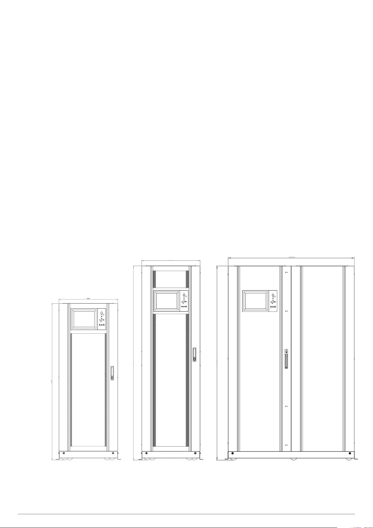
Fig. 1 to Fig. 13 show the views and dimensions (in mm) of
6-slot (180 kVA) and 10-slot (300 kVA and 500 kVA) devices.
Because the product is constantly evolving, however, slight
discrepancies or contradictions may arise. If in any doubt, the
labelling on the device itself will always prevail.
1600
600
2000
600
1300
2000
Fig. 1. General view of 6- and 10-slot cabinets.
SLC ADAPT UNINTERRUPTIBLE POWER SUPPLY (UPS)USER'S MANUAL
7
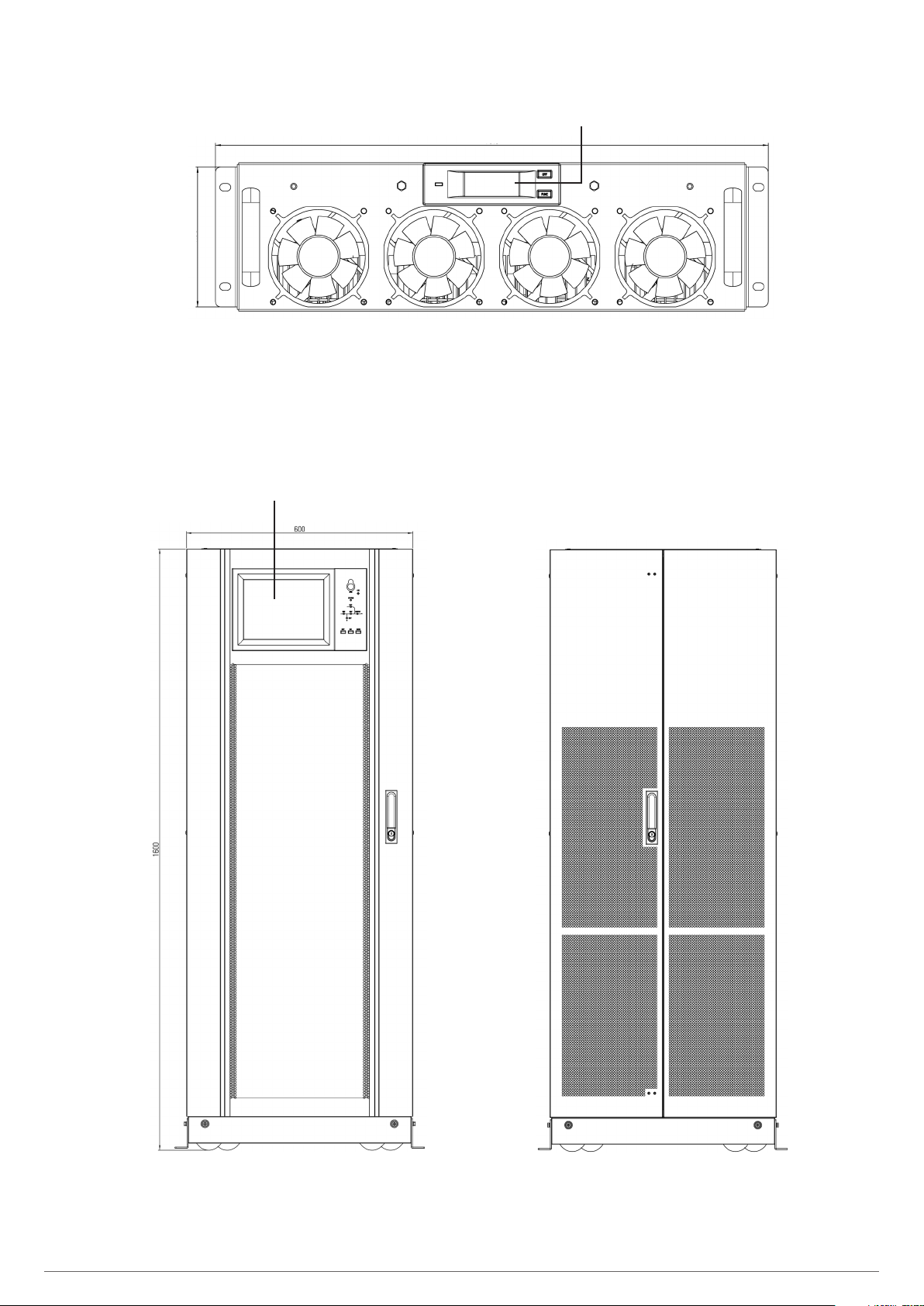
4.98
Fig. 2. Front view of 30 kVA module
(20 kVA for 3x208 V AC voltages).
Touch display
LCD
19.8
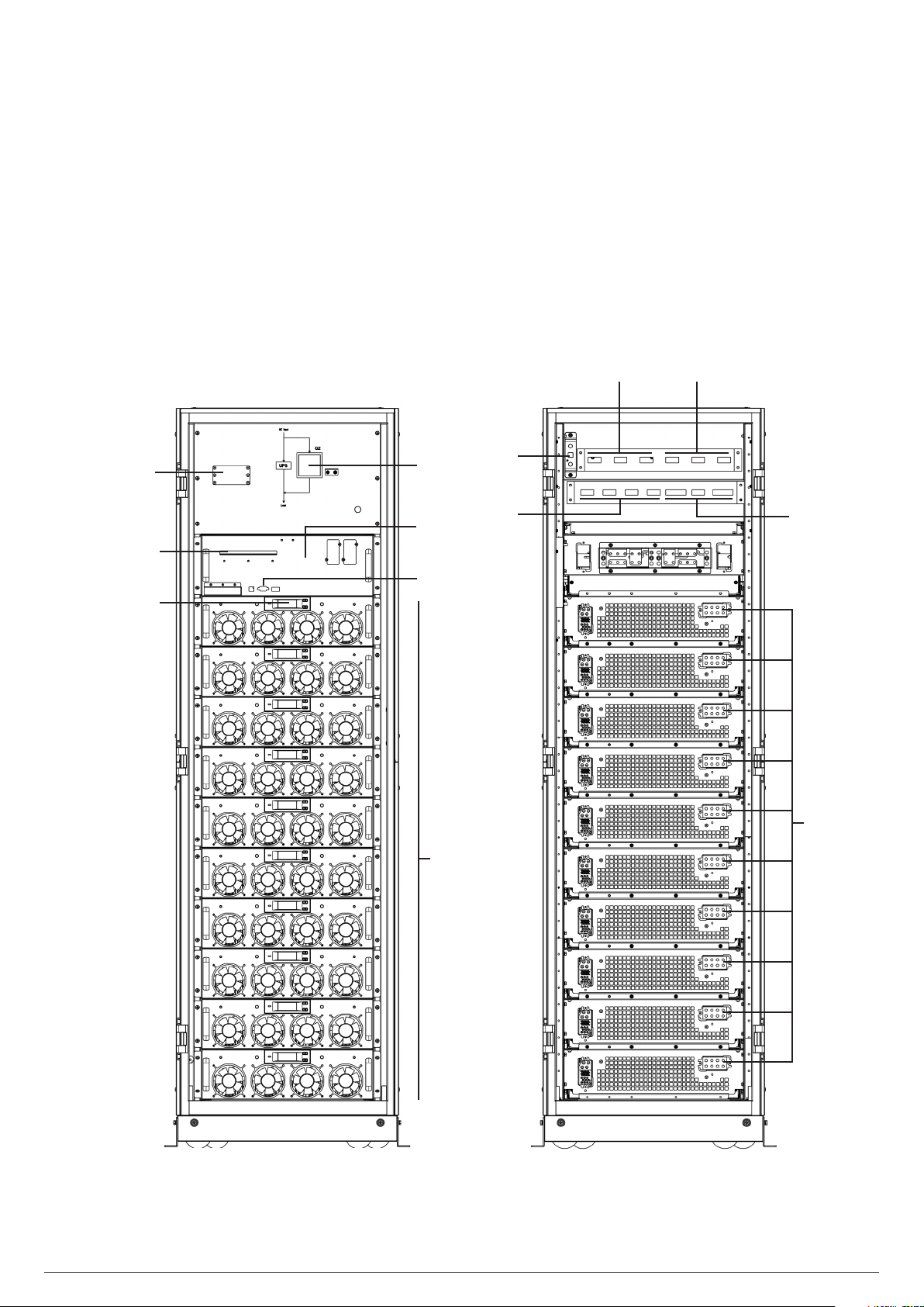
Fig. 3. Front and rear view of 6-slot cabinet - 180 kVA
(120 kVA at 3x208 V) with closed doors.
8 SALICRU
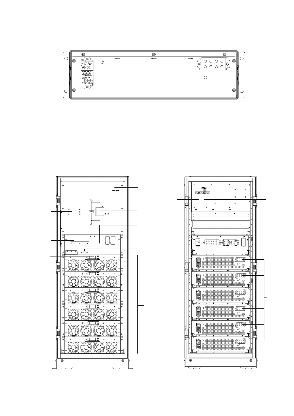
Fig. 4. Rear view of 30 kVA module
(20 kVA for 3x208 V AC voltages).
Bypass input
A B C N
SPD
(option)
Relay
interface
Module
display
Cold Start
Manual bypass
marking
Free slot for
Bypass module
Communications
interface
30kVA power
modules
Output
A B C N
Batteries
+ N –
Input
A B C N
Power
module
connector
Fig. 5. Front and rear view of 6-slot cabinet - 180 kVA
(120 kVA at 3x208 V) with open doors.
SLC ADAPT UNINTERRUPTIBLE POWER SUPPLY (UPS)USER'S MANUAL
9
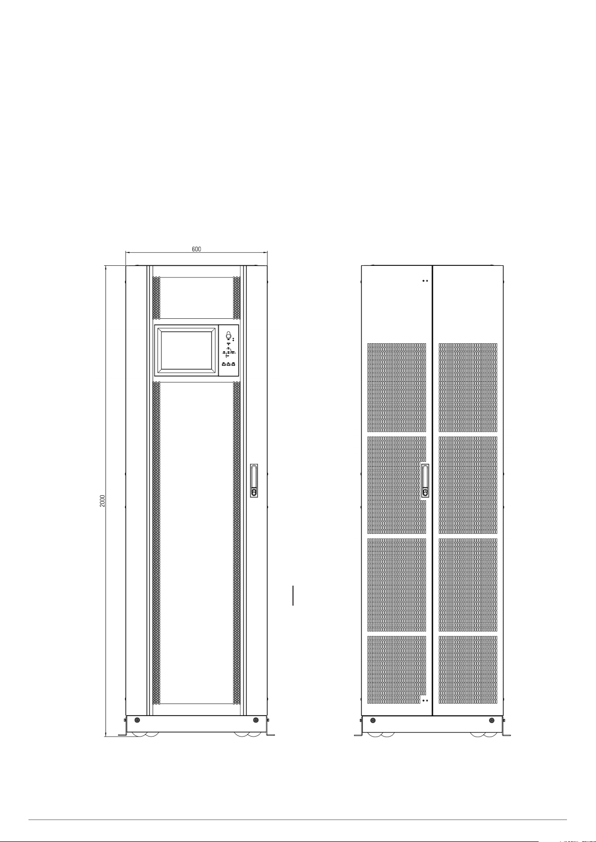
Fig. 6. Front and rear view of 10-slot cabinet - 300 kVA
(200 kVA at 3x208 V) with closed doors.
10 SALICRU
Bypass input
A B C N
Input
A B C N
SPD
(option)
Relay
interface
Module
display
Cold Start
Manual bypass
marking
Free slot
for Bypass
module
Communications
30 kVA power
A B C N
interface
modules
Output
PE
Batteries
+ N –
Power
module
connector
Fig. 7. Front and rear view of 10-slot cabinet - 300 kVA
(200 kVA at 3x208 V) with open doors.
SLC ADAPT UNINTERRUPTIBLE POWER SUPPLY (UPS)USER'S MANUAL
11
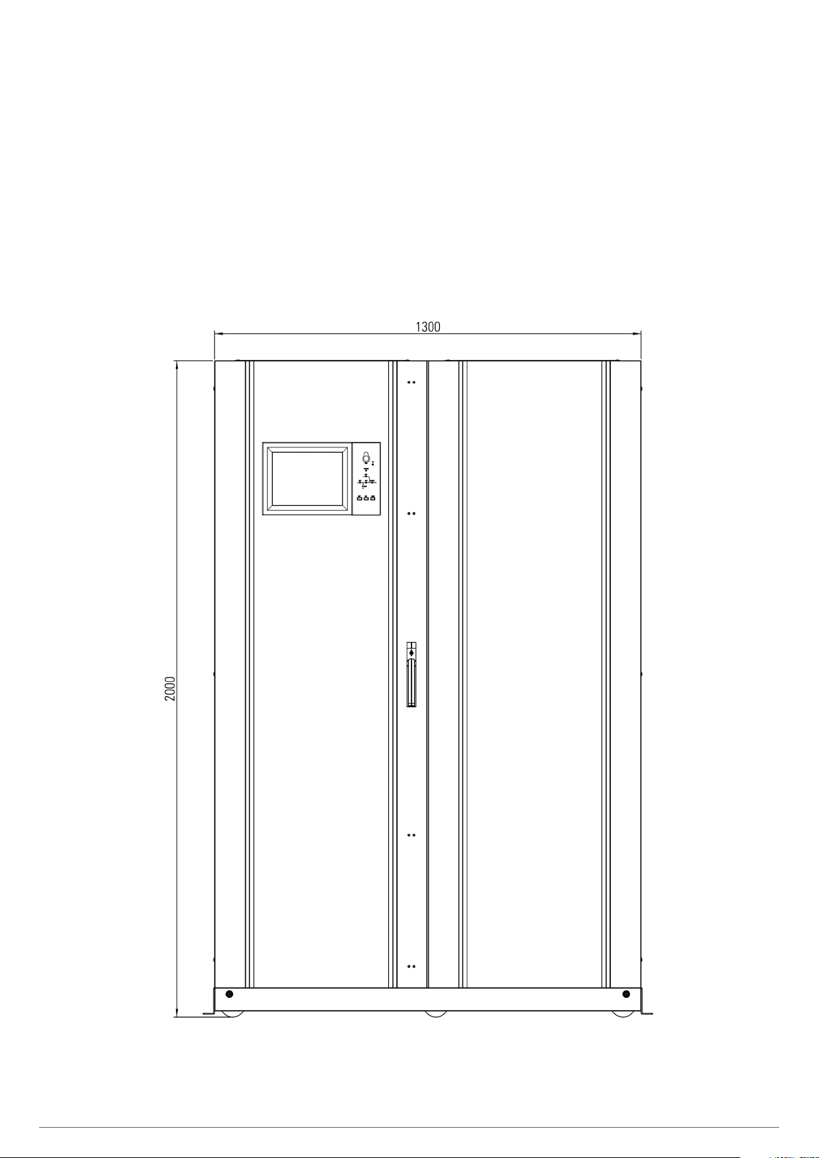
Fig. 8. Front view of 10-slot cabinet - 500 kVA
(300 kVA at 3x208 V) with closed doors.
12 SALICRU
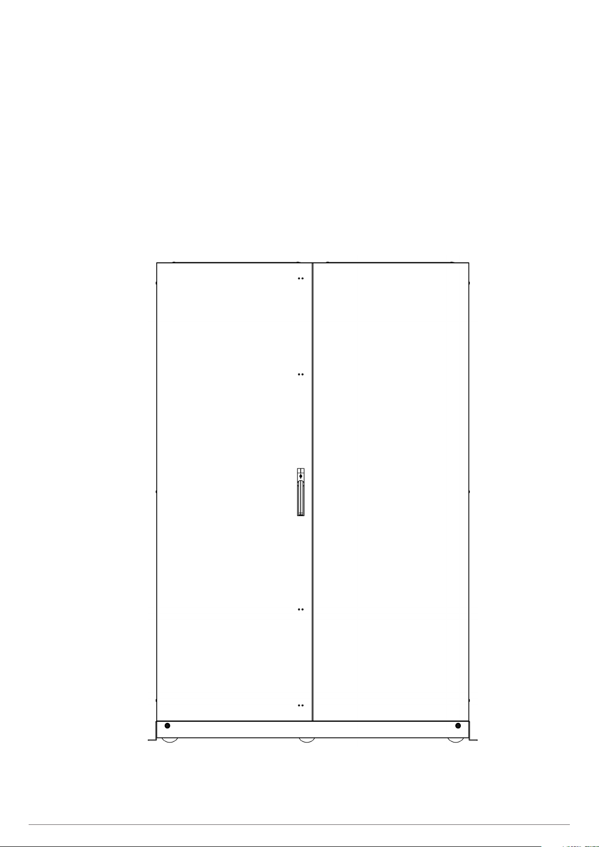
Fig. 9. Rear view of 10-slot cabinet - 500 kVA
(300 kVA at 3x208 V) with closed doors.
SLC ADAPT UNINTERRUPTIBLE POWER SUPPLY (UPS)USER'S MANUAL
13
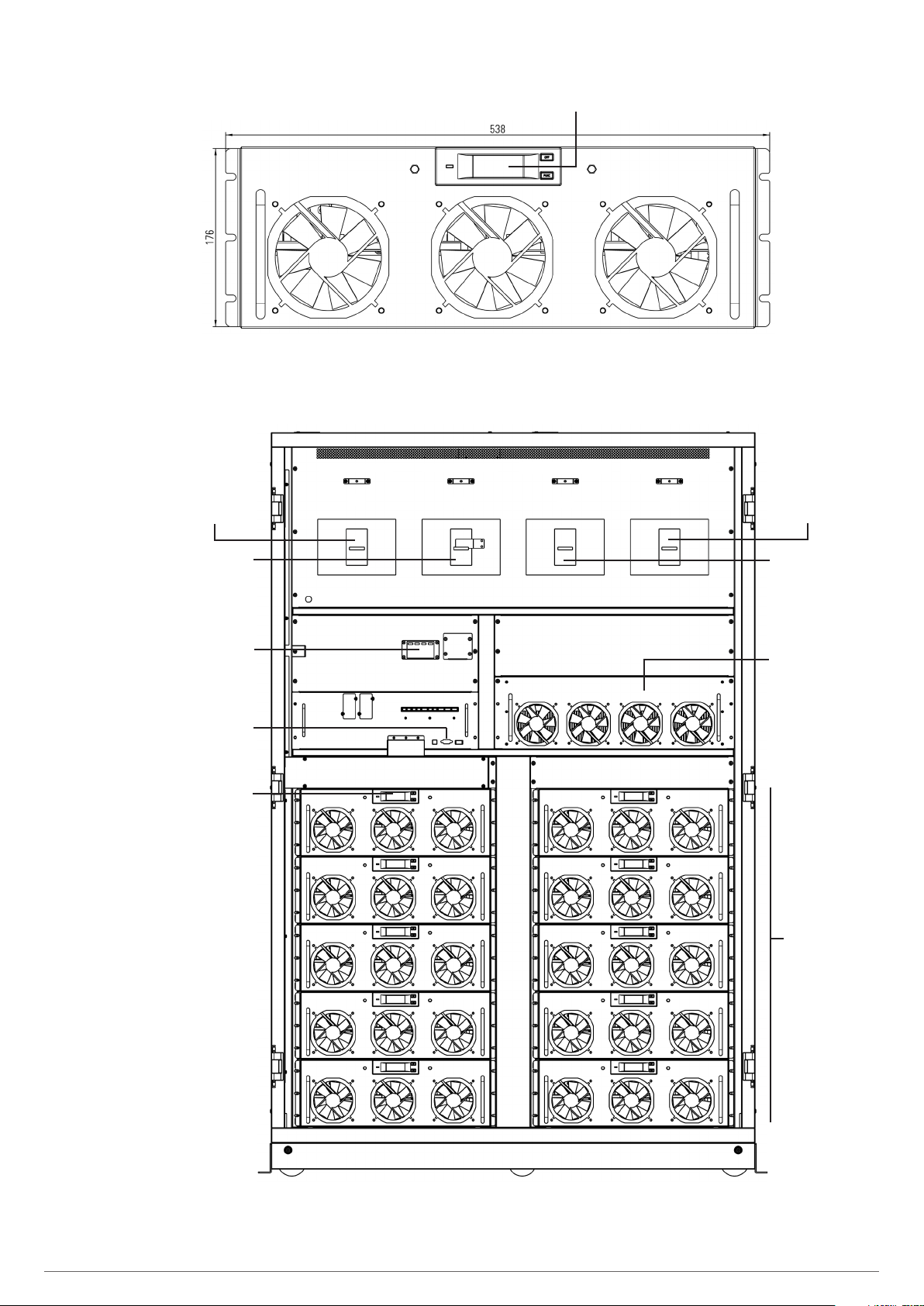
Fig. 10. Front view of 50kVA module
(30 kVA for 3x208 V AC voltages).
LCD
UPS input
disconnector
Manual Bypass
disconnector
SPD (Surge Protection Device)
(Optional)
Communications
interface
Module
display
UPS input
Cold Start
Q1
Manual bypass
Bypass input UPS output
Q2 Q4 Q3
UPS output
disconnector
Bypass input
disconnector
Bypass
module
50 kVA power
modules
Fig. 11. Front view of 10-slot cabinet - 500 kVA
with open doors.
14 SALICRU
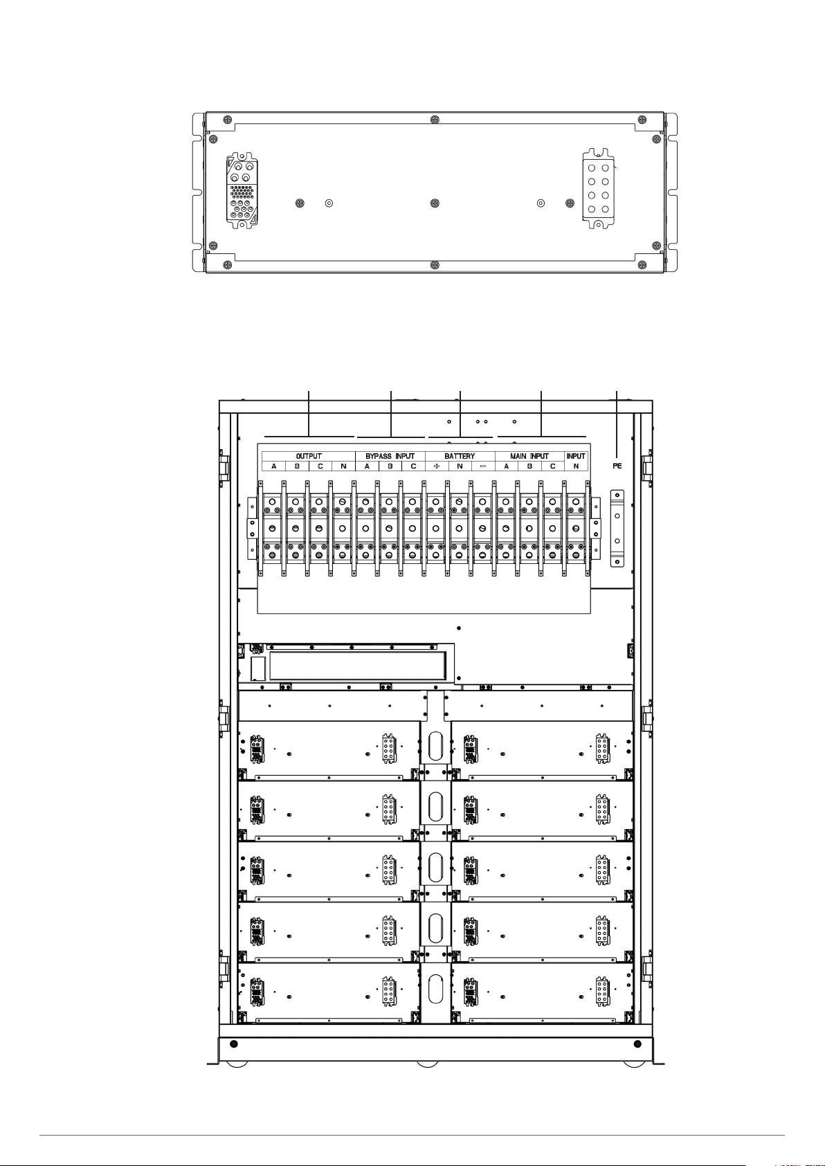
Fig. 12. Rear view of 50 kVA module
(30 kVA for 3x208 V AC voltages)
Output
A B C N
Bypass input
A B C
Batteries
+ N –
Input
A B C N
PE
Fig. 13. Rear view of 10-slot cabinet - 500 kVA
with open doors.
SLC ADAPT UNINTERRUPTIBLE POWER SUPPLY (UPS)USER'S MANUAL
15
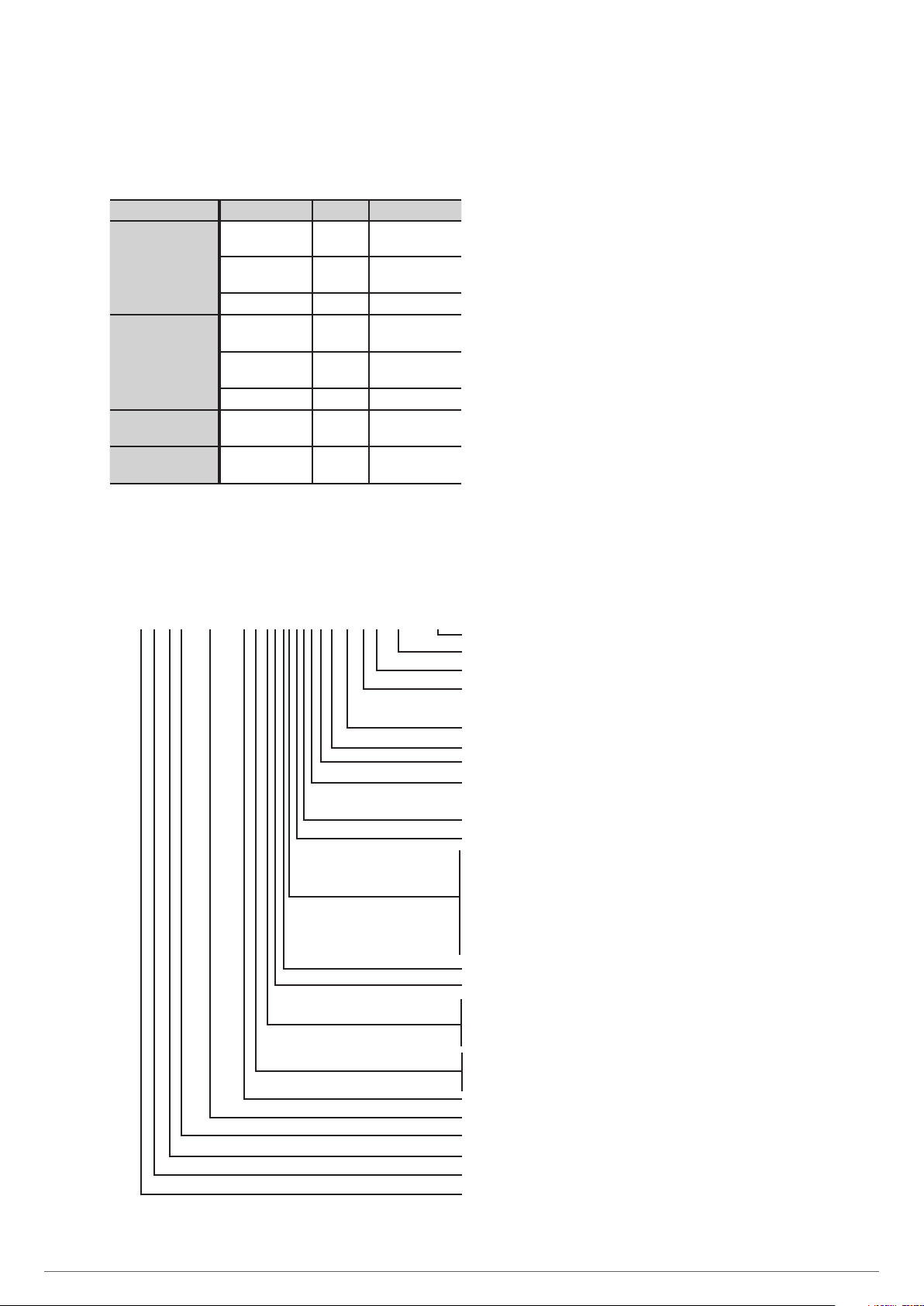
4.1.2. Device configurations.
The following table provides information about the configuration of the UPS:
Item Components Quantity Note
Requirement,
installed in factory
Requirement,
installed in factory
Requirement,
installed in factory
Requirement,
installed in factory
Requirement,
installed on site
Requirement,
installed on site
6-slot cabinet
10-slot cabinet
30 kVA power
module
50 kVA power
module
Manual bypass 1
Bypass and
monitoring module
Dust filter 1 Optional
Manual bypass 1
Bypass and
monitoring module
Dust filter 1 Optional
Power module 1-10
Power module 1-10
1
1
4.2. DEFINITION OF THE PRODUCT.
4.2.1. Nomenclature.
SLC-6+1/10A-ADAPT 100X R P2LBDCS B1 0/36AB165 EE116502
EE Special device EE
165 Last three digits of the battery code
AB Letters of the battery family
36 Number of batteries in a single branch. For banks of common
batteries, all batteries in the system will be indicated
0/ Devices prepared for standard backups
B1 Subrack/cabinet with external batteries
S Ambient temperature sensor
C Subrack mounted on box-type BATT MOD (batteries supplied
factory mounted)
D Transient protection filter
B Independent bypass line
L Single-phase input/single-phase output device
N Three-phase input/single-phase output devices (independent
bypass line must be included)
M Single-phase input/three-phase output device (independent
bypass line must be included)
Three-phase input/three-phase output device
2 Number of subracks/cabinets in parallel
P Material needed to parallel subrack/cabinets
R ADAPT X series device in subrack format (subrack not inte-
grated into a cabinet)
Y IP20 protection rating with open door and keyless lock
X Indication for modules with 2U height. Disregard for ≥3U
modules
100 Total power of subrack/cabinet
ADAPT UPS series
A,B,C Cabinet type
10 Total number of slots in subrack/cabinet
1 Number of redundant modules (disregard if none)
6 Number of modules installed in subrack/cabinet without
taking into account redundancy
16 SALICRU
4.3. GENERAL DESCRIPTION.
4.3.1. Introduction.
The SLC ADAPT series is classified as an on-line doubleconversion uninterruptible power supply with DSP control and
three-level IGBT inverter technology, modular topology and
great flexibility.
Reliability: The DSP control associated with three-level PWM
technology increases the performance of the system and, together
with the redundancy of the modules, manages to increase the
availability of power to the critical loads, a parameter that
contributes to achieving a good TIER classification for the entire
system.
Availability: Its hot-swap modules can be added or replaced
during operation, thereby improving mean time to repair
(MTTR) and reducing maintenance costs. Moreover, both the
control display and the bypass module can be replaced without
affecting the operation of the device. In addition, the system’s remote management, which can be integrated into any
platform, also makes operation easier. The extensive backup
options available, along with smart battery charging, ensure
continuous operation of the protected critical loads.
Modularity: This allows simple configurable solutions from
30 to 1500 kVA by installing 30 or 50 kVA modules in the 6-slot
(30 kVA modules) or 10-slot cabinets. As composite solutions,
a maximum of 30modules can be paralleled to obtain higher
power systems or N+n structures. Either way, it is only possible
to install identical modules in the same cabinet and/or parallel
cabinets with modules of equal power. This enables gradual
growth and scaling for future expansion depending on the
need for pay-as-you-grow protection, improving the total cost
of ownership (TCO) and providing a high level of flexibility. At
operational level, a cabinet consisting of ‘N’ modules connected
in parallel is considered a single UPS.
Any expansion or structural change to the number of modules
is possible even during normal operation and without needing
to shut down the hot-swappable system, all with the simple
use of a screwdriver to remove or screw the fixing screws of
the module(s). Although all of the UPS’s modules incorporate a
battery charger that can allocate up to 20% of its rated power
to maintaining them at an optimum charge level depending on
the type and number of elements, 50 A battery charger modules
are available to be installed solely with the 30 kVA SLC ADAPT
modules. As many charging modules as considered appropriate
can be installed, but this will be to the detriment of the total
number of UPS modules and, consequently, the total power of
the system, which will be reduced.
Backup: The capacity of the batteries determines the backup
time of the system when replacing the usual source of energy
during mains failures. The accumulator bank is always common
to any system mounted in the same cabinet. Batteries owned by
the customer or supplied with the UPS, depending on different
factors in addition to the power and/or backup requested, can
be installed in a back or one or more cabinets, always external
to the UPS itself.
SLC ADAPT series UPSs basically consist of:
• 6- or 10-slot cabinet to install the power modules.
• Power modules consisting of the following blocks:
AC/DC PFC rectifier.
Battery charger.
DC/AC inverter.
Digital control and UPS management.
• Centralised bypass module: control of UPS and parallel pa-
rameters.
• Maintenance bypass.
• Control panel with touch screen (see section X for more
information).
• Batteries (number, type and location depending on the
backup time).
• Self-supporting 36 and 46U cabinets for the placement of
the different modules.
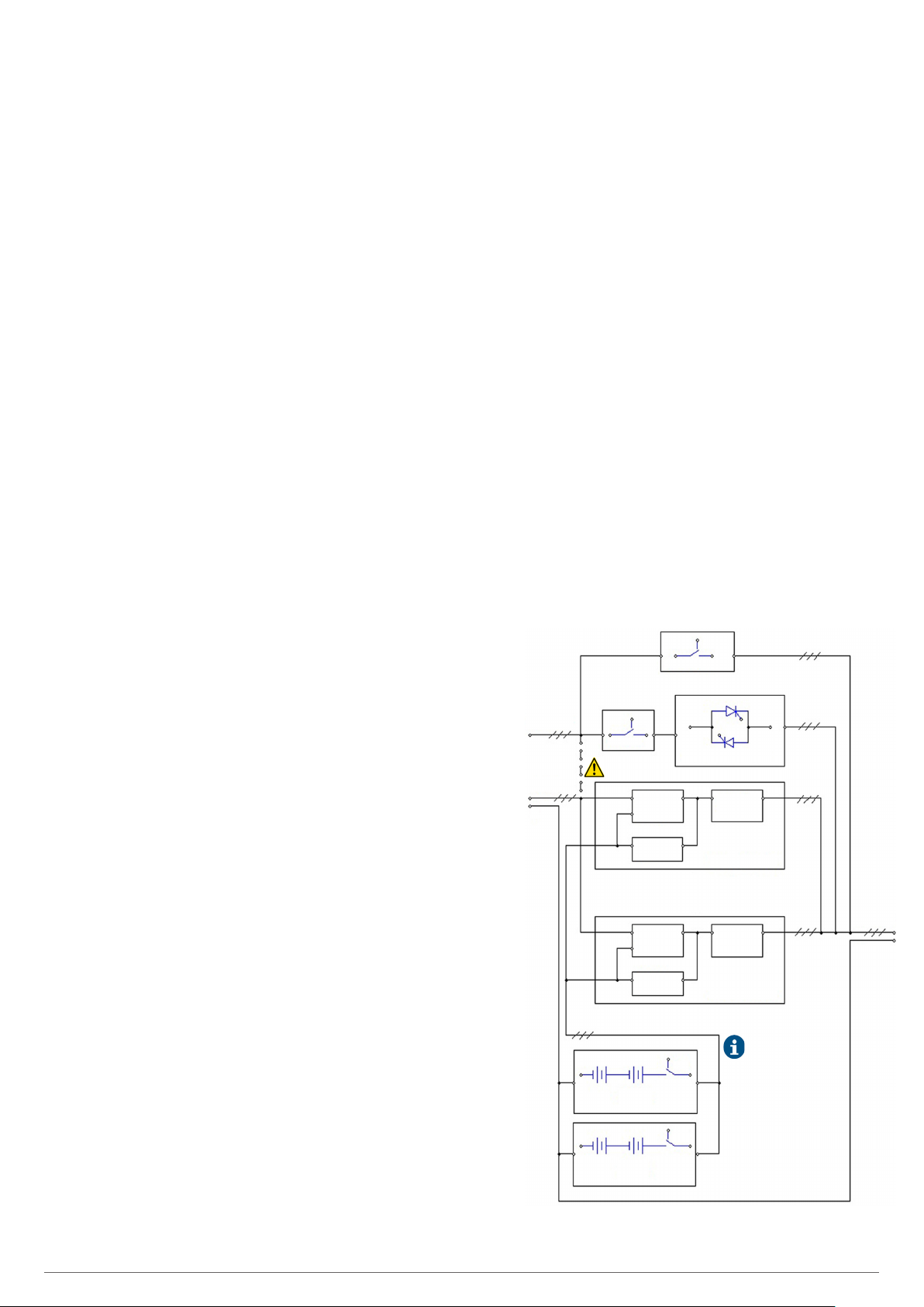
4.3.2. Conceptual diagram of the system.
The modular UPSs of the SLC ADAPT series consist of power
modules, a bypass and monitoring module, and a cabinet with
a range of disconnectors for Input, Bypass Output and Manual
Bypass. The 180 and 300 kVA UPSs only have a manual bypass
switch. One or more battery branches should be installed to
provide backup power in the event of a power failure. The
structure of the UPS is shown in Fig. 14.
Q2
MANUAL BYPASS
STATIC BYPASS
LINE INPUT -R, S, T-
INLET LINE OF UPS
-R, S, T-
N
Q1
BYPASS
Connection strips
between phases for mains.
REC / PFC
BAT / DC
DC / DC
INVERTER
REC / PFC
BAT / DC
DC / DC
INVERTER
BATTERY MODULE
STATIC BYPASS MODULE
DC / AC
INVERTER
POWER MODULE # 1
•
•
•
DC / AC
INVERTER
POWER MODULE #N
BCB
BCB
The batteries are represented in
the structural diagram as they are
an essential part of all UPSs,
although they will never be
included in the cabinet itself. The
batteries can be supplied in a
separate cabinet, in a bank or not
supplied if the customer already
has them.
OUTPUT
U, V, W
N
BATTERY MODULE
Fig. 14. Conceptual diagram of the SLC ADAPT series
modular UPS.
SLC ADAPT UNINTERRUPTIBLE POWER SUPPLY (UPS)USER'S MANUAL
17

Fig. 14 shows, byway of example, a single-line diagram of the
device with three-phase input and output.
All modules in the cabinet are structured according to the same
criteria, terminals for the power supply of the PFC rectifier and
independent static bypass, and input, output, static bypass
and manual bypass disconnectors. However, unless otherwise
requested, for separate networks originally from the factory,
the terminals of the phases of both blocks are connected by
means of strips to provide a single common input.
When separate power supplies are required, it is
obligatory to remove the strips between the phases of
both blocks before connecting the power cables, leaving the
connection strip of the neutral terminals.
4.3.2.1. Power modules (PM).
Power modules are the basic core of the entire SLC ADAPT
system. Apart from the static bypass block and LCD touch
screen, each power module contains all of the converters and
functionalities of a traditional UPS. Since this device consists
of a number of variable modules depending on the cabinet
used, a multi-parallel system is obtained with the behaviour
equivalent to that of a single mono-bloc UPS and the advantages of a modular UPS.
The system supplies power to the critical load (such as communication and data processing equipment) with uninterrupted
high quality AC power. The power supplied by the unit is stable,
without voltage and/or frequency variations and free from
other disturbances such as cuts or micro-cuts, sine wave alterations, electrical noise, anomalies commonly present in the
commercial AC network.
This is achieved through the double-conversion high frequency
Pulse Width Modulation (PWM), in combination with a digital
control based on a Digital Signal Processor (DSP), which provides high reliability and availability.
As can be seen in Fig. 14, the AC power supplied to the UPS
input is converted into DC voltage. This voltage supplies a converter that transforms the voltage type from DC to AC, clean of
disturbances and variations of the AC input mains. If this fails,
the PFC rectifier changes the input source of the AC mains to
that of the batteries, powering in the same way through the
output of the UPS to the load for a limited time, that of the
backup determined by the battery pack.
4.3.2.1.1. Available power ratings.
The SLC ADAPT series has two different power modules, 30
and 50 kVA, as can be seen in Fig. 2, Fig. 4, Fig. 10 and Fig. 12.
4.3.2.2. Static bypass.
Static transfer switch.
In the event of inverter failure, overload or overtemperature,
the voltage connected to the static bypass line can supply
power to the load connected to the UPS output.
The static bypass module identified in Fig. 14 contains the
power management and control circuits that allow the most
optimum decision in each scenario to be made, in order to select the most favourable power to the critical load connected
to the output of the UPS, either from the inverter or from the
static bypass itself.
During normal system operation, the load is connected to the
inverter and in case of overload or failure, it will automatically
transfer to the static bypass line. In order to provide a clean
transfer (without interruption) between the inverter output and
the bypass line, they must be fully synchronized during normal
operation. This is achieved through real-time digital control of
the inverter, so that the frequency of the inverter follows the
frequency of the bypass line if the bypass is within the range of
acceptable frequencies.
In addition, a Manual Bypass, which is very useful during periods
of maintenance or failure, is included and allows continuous
powering of the critical load while the UPS is out of service.
When the UPS is operating in bypass mode (over static
bypass), connected devices are not protected against
power cuts or micro-cuts, overvoltages, voltage and/or frequency variations as they are powered directly from the AC
mains.
4.3.2.3. Extra charger modules for 180 and 300 kVA devices.
The smart charging module is designed to supply the necessary
charging current for long backup applications. The module is hot
swappable and has the same size and appearance of any power
module, supplying an adjustable current of between 0 and 50 A.
On the front, they have a high resolution LCD where the user
can monitor the different load parameters in real time.
The modules are designed to be inserted in 6- and 10-slot
cabinets with only 30 kVA modules - 180 and 300 kVA devices
- and can be inserted in the necessary number to meet battery
charging needs.
4.3.2.3.1. Wiring diagram.
As can be seen in the diagram in Fig. 15, the charger modules
are connected in parallel to the power modules. The total current of the system is the sum of the current supplied by the
power modules and the charger modules.
18 SALICRU
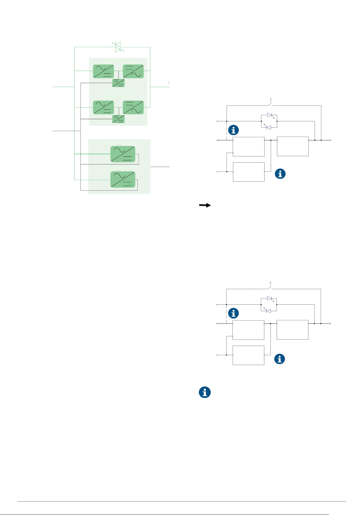
4.3.3.1. Normal mode.
Power module 1
Input
terminal
Battery
terminal
Power module n
Power modules
Charger module 1
Charger module m
Extra charger modules
Output
terminal
Fig. 15. Conceptual diagram of the extra charger modules.
4.3.3. UPS operating modes.
The modular double-conversion on-line UPS has the following
operating modes:
• Normal mode
• Battery mode
• Bypass mode
• Maintenance mode (manual bypass)
• ECO mode
• Frequency converter mode
During the description of the operating modes the operation
is described referring to the PFC-rectifier and inverter parts as
functional parts of a module, although there will be as many of
them as there are modules connected in parallel.
The inverter of each power module is responsible for powering
the critical loads at all times. The rectifier/charger of the AC
input powers the inverter with DC voltage while simultaneously
charging the associated backup battery, either at float or quick
voltage.
AC / DC
BAT / DC
Charger
Manual bypass
Inverter
DC / AC
Connection strips between
phases for mains.
AC output
AC input
Bypass
AC input
Rectifier
Batteries
Static bypass
PFC rectifier
DC / DC Battery
Fig. 16. Conceptual diagram of the UPS in Normal mode.
Indicates the direction of the energy flow.
4.3.3.2. Battery mode.
In the event of failure of the AC input power mains, the inverter,
by means of the power it obtains from the battery, supplies the
critical loads of the output in AC. By doing so, the power supply
is not interrupted in the event of failure. Once the AC power
input is restored, the ‘Normal mode’ function will be restored
automatically without the user needing to intervene.
AC / DC
BAT / DC
Manual bypass
Inverter
DC / AC
AC output
AC input
Bypass
AC input
Rectifier
Static bypass
PFC rectifier
DC / DC Battery
Batteries
Charger
Connection strips between
phases for mains.
Fig. 17. Conceptual diagram of the UPS in Battery mode.
With the Battery Cold Start function, the UPS can be
started without mains power. See details in section
6.1.2.
SLC ADAPT UNINTERRUPTIBLE POWER SUPPLY (UPS)USER'S MANUAL
19
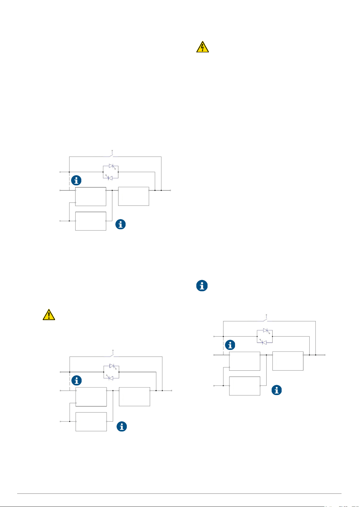
4.3.3.3. Bypass mode.
If the inverter’s overload capacity is exceeded in Normal
mode, or if the inverter cannot supply power to the loads for
any reason, the static switch will transfer the inverter’s load
to bypass, without interrupting the power to the critical loads.
If the inverter is not synchronised with the bypass, the static
switch will transfer the load from the inverter to the bypass,
interrupting the load. This is done to prevent short circuits due
to the paralleling of non-synchronised AC inputs. The time of
this interruption is programmable, the typical value being less
than 3/4 of a cycle, e.g. less than 15 ms (50Hz) and 12.5 ms
(60Hz). The transfer or retransfer action can be performed via
commands through the control panel.
AC / DC
BAT / DC
Charger
Manual bypass
Inverter
DC / AC
Connection strips between
phases for mains.
AC output
AC input
Bypass
AC input
Rectifier
Batteries
Static bypass
PFC rectifier
DC / DC Battery
DANGER: During manual bypass mode, the input,
output and bypass terminals (version B) are live even if
all modules are switched off.
It is recommended in this operating mode:
– Remove the fastening screws of all power, control
and bypass modules.
– Slightly pull the handles on each one until they are
protruding by about 4-5 cm from their housing in
order to enable them to be unplugged from their
connector located on the backplane of the device.
Before any change of operating mode and after carrying out the
possible corrective actions, it is necessary to correctly insert
the modules to their original position and fix them with their
screws.
4.3.3.5. Parallel-Redundant mode.
This operating mode allows to obtain a greater capacity, reliability or both, being able to be configured like extension of
power or like redundancy.
As a consideration to be taken into account when the cabinets
are in parallel, the controller included in each one guarantees
the automatic distribution of the load in all of them and all of
its modules.
4.3.3.6. ECO mode.
Fig. 18. Conceptual diagram of the UPS in Bypass mode.
4.3.3.4. Manual Bypass mode (maintenance bypass).
If the UPS requires intervention due to breakdown or maintenance (for example, because there is a power module, the
bypass or the LCD with anomalies), there is the possibility of
continuing to supply the loads through the internal manual bypass (maintenance bypass).
When the UPS is operating in ‘Manual Bypass Mode’
(maintenance or repair period), the connected equipment is not protected against power cuts or micro-cuts, overvoltages, voltage and/or frequency variations, etc. when fed
directly from the commercial AC network.
Inverter
DC / AC
AC output
AC input
Bypass
AC input
Rectifier
Manual bypass
Static bypass
PFC rectifier
AC / DC
BAT / DC
ECO mode saves energy. In this mode, when the input voltage
of the Bypass is within the ECO voltage range, the static bypass
that supplies power directly to the loads is activated, leaving
the inverter in standby. When the Bypass voltage or frequency
is out of range, the UPS transfers the output to Inverter.
During the transfer of the load on the inverter from ECO
mode, a small interruption (less than 10 ms) occurs. It is
very important to ensure that the critical load powered in this
UPS mode tolerates that interruption time.
AC / DC
BAT / DC
Charger
Manual bypass
Inverter
DC / AC
Connection strips between
phases for mains.
AC output
AC input
Bypass
AC input
Rectifier
Batteries
Static bypass
PFC rectifier
DC / DC Battery
Fig. 20. Conceptual diagram of the UPS in ECO mode.
Batteries
DC / DC Battery
Charger
Connection strips between
phases for mains.
Fig. 19. Conceptual diagram of the UPS in manual Bypass
mode (maintenance).
4.3.3.7. Frequency converter mode.
When operating in this mode, the device supplies a fixed
output frequency of 50 or 60 Hz, or different input and output.
When operating in this mode, the static bypass is inhibited
and the manual bypass switch should not be operated due to
the consequences it could have on the loads connected to the
output.
20 SALICRU
 Loading...