

SALDA Smarty 2 R VEL plus, Smarty 2 R VER, Smarty 2 R VEL, Smarty 2 R VER plus MOUNTING AND INSTALLATION INSTRUCTION

EN MOUNTING AND INSTALLATION INSTRUCTION
SMARTY R V

1. CONTENTS
2. SYMBOLS AND MARKING 4
3. SAFETY INSTRUCTIONS AND PRECAUTIONS 4
4. INFORMATION ABOUT THE PRODUCT 5
4.1. DESCRIPTION 5
4.2. DIMENSIONS AND WEIGHT 5
4.3. TECHNICAL DATA 5
4.3.1. AIR FLOW DIAGRAMS 7
4.4. OPERATING CONDITIONS 7
4.5. STANDARD PACKAGE OF COMPONENTS 8
4.6. DESCRIPTION OF COMPONENTS 8
4.7. SPARE PARTS 8
5. INSTALATION 9
5.1. RECEPTION OF GOODS 9
5.2. TRANSPORTATION AND STORAGE 9
5.3. UNPACKING 10
5.4. MOUNTING DIAGRAM 10
5.5. MOUNTING 11
5.5.1. MOUNTING ON THE WALL 11
5.5.2. PLACE REQUIREMENTS FOR THE EQUIPMENT AND MOUNTING POSITIONS 11
5.5.3. CONNECTION OF AIR DUCTS 12
5.5.4. AIR FLOW 12
5.5.5. CONNECTION OF THE KITCHEN HOOD 12
5.5.6. SHIELD INSTALLATION 13
5.6. CONNECTION OF THE UNIT TO ELECTRIC NETWORK 13
5.7. START-UP RECOMMENDATIONS 13
5.7.1. SYSTEM PROTECTION 13
5.7.2. PRE-STARTUP RECOMENDATIONS OF THE UNIT (IN THE PRESENCE OF THE ENDUSER) 14
6. MAINTENANCE 14
6.1. SAFETY INSTRUCTION 14
6.2. COVER OPENING 14
6.3. FILTERS MAINTENANCE 15
6.4. FANS MAINTENANCE 15
6.5. HEATER MAINTENANCE 16
6.6. ROTOR MAINTENANCE 16
7. CONTROL 17
7.1. DEVICE CONTROL 17
7.2. MEANING OF THE SYMBOLS USED IN THE INSTRUCTIONS AND ON THE DEVICE 17
7.3. DESCRIPTIONS OF THE FUNCTIONS 17
7.4. DESCRIPTION OF THE UNITS FUNCTIONS 18
7.4.1. SYSTEM MODES 18
7.4.2. SYSTEM CONTROL 19
7.4.3. SYSTEM STATES 20
7.4.4. SETTING DATE AND TIME 20
7.4.5. SUPPLY AIR TEMPERATURE CONTROL AND COMPENSATION 20
7.4.6. FAN CONTROL 21
7.4.7. “BOOST“ FUNCTION 21
7.4.8. WEEKLY SCHEDULE 21
2 | EN SMARTY RV v2019.12

7.4.9. HOLIDAY SCHEDULE 21
7.4.10. WINTER/SUMMER MODE 21
7.4.11. DRYNESS PROTECTION 21
7.4.12. NIGHT COOLING FUNCTION 22
7.4.13. CO2 REDUCTION FUNCTION 22
7.4.14. FILTER PROTECTIONS 22
7.4.15. SYSTEM MODE COMMUNICATION WITH EXTERNAL CONTACTOR 22
7.4.16. FAN SPEEDS FROM AN EXTERNAL SYSTEM CONTACTOR 22
7.4.17. HEAT EXCHANGER CONTROL 23
7.4.18. SYSTEM MONITORING 23
7.4.19. STAND-BY MODE BLOCKING 23
7.4.20. AIR FLOW ADJUSTMENT 23
7.4.21. MANUAL CONTROL OF COMPONENTS 23
7.4.22. CHANGING PASSWORDS 24
7.4.23. RESTORING FACTORY DEFAULTS 24
7.4.24. INDICATIONS OF FUNCTIONS, ALARMS AND WARNINGS 24
7.4.25. DISPLAY AND CONCELLATION OF ALARMS AND WARNINGS 24
7.4.26. EVENT LOG (HISTORY) 25
7.4.27. SYSTEM VERSIONS AND RUNNING TIME 26
8. ACCESSORIES 26
8.1. CONNECTION FO ACCESSORIES 27
8.1.1. SCHEMATIC OF CONTROLLER CONNECTIONS IN MCB 27
8.1.2. CO2 SENSOR OR CONNECTION OF HUMIDITY SENSOR RH 29
8.1.3. ROOM CO
TRANSMITTER INSTALLATION RECOMMENDATION 30
2
8.1.4. CO2 CONCENTRATION ACCORDING TO PETTENKOFER LIMIT 31
8.1.5. FIRE PROTECTION INPUT (NC) 31
8.1.6. EXTERNAL SWITCHES 31
8.1.7. CONNECTION OF REMOTE CONTROL PANEL OR MODBUS 32
8.1.8. “MCB TOOL” PROGRAM DESCRIPTION 32
8.2. THE PRINCIPAL CONNECTION SCHEME OF INTERNAL AND EXTERNAL COMPONENTS 34
8.3. ELECTRICAL CONNECTION OF THE UNITS 48
9. POSSIBLE FAULTS AND TROUBLESHOOTING 49
10. SENSORS AND THEIR TECHNICAL INFORMATION 49
11. INSPECTION OF THE VENTILATION SYSTEM 49
12. ECODESIGN DATA TABLE 50
13. DECLARATION OF CONFOMITY 51
14. WARRANTY 52
14.1. LIMITED WARRANTY COUPON 52
EN | 3SMARTY RV v2019.12
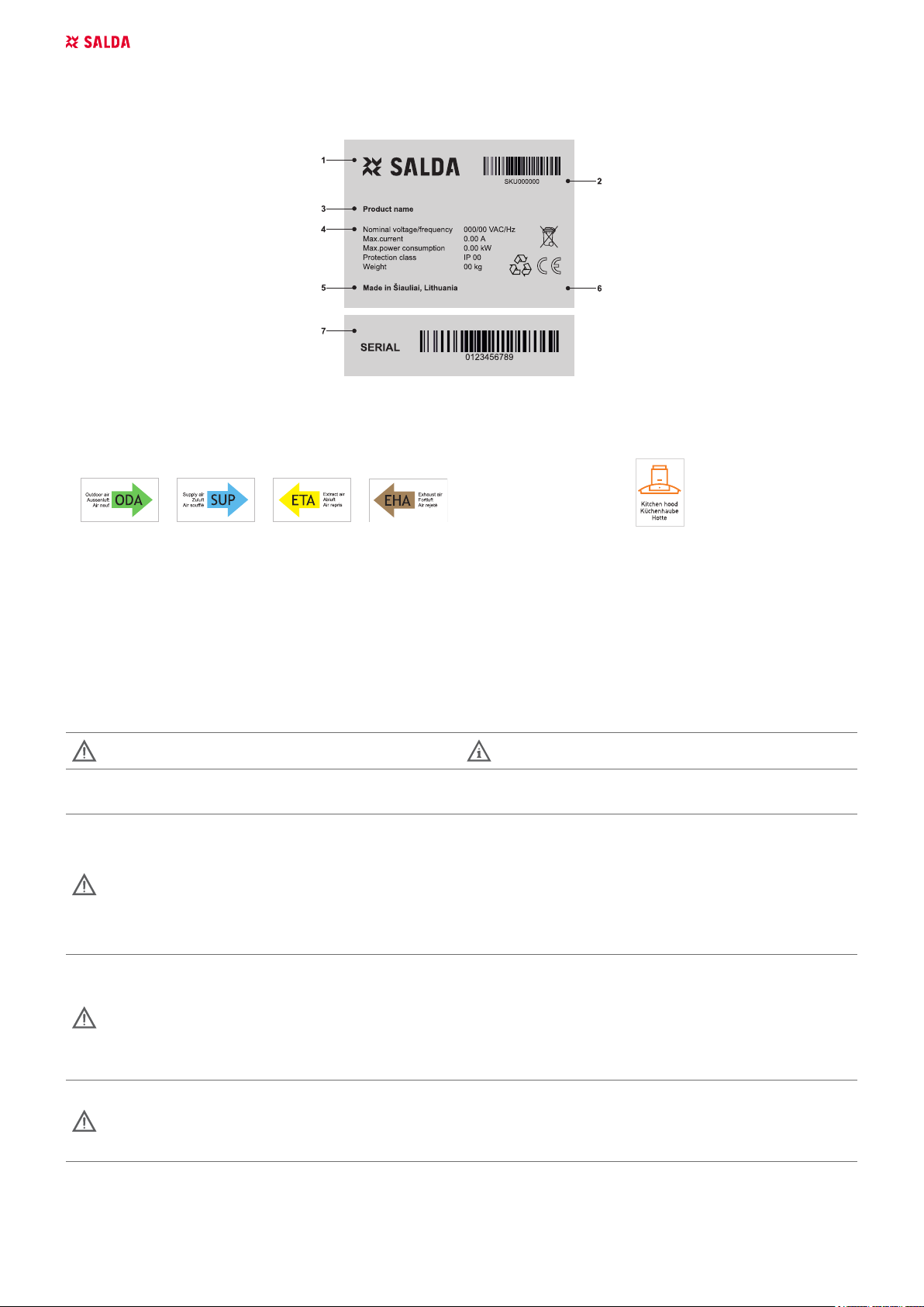
2. SYMBOLS AND MARKING
LN: XX000000
2019.01.01
Stick the auxiliary label on the unit (on an easily accessible place) or on the dashed place of a technical manual in order to keep the important
information about the unit.
LN: XX000000
2019.01.01
Figure 2.1 - Technical label
1 - Logo; 2 - Product code (SKU); 3 - Product name; 4 - Technical data; 5 - Production place; 6 - Batch number and production date; 7 - Serial
number.
Figure 2.2 - Indication for duct connection. Figure 2.3 - indication of kitchen hood
ODA - outdoor air; SUP - supply air; ETA - extract air; EHA - exhaust air.
3. SAFETY INSTRUCTIONS AND PRECAUTIONS
Read this instruction very carefully before installing and using this equipment. Installation, connection and maintenance should be carried out by
a qualifed technician and in accordance with the local rules and legal acts.
The company shall take no responsibility for the injuries suered by the people or for the damaged property, if the safety requirements are not
followed or the device is modifed without the permission of the manufacturer.
Warning – pay attention Additional information
Main safety rules
Danger
• Before performing any electricity or maintenance tasks make sure, that the device is disconnected from the mains, that all moving parts
of the device have stopped.
• Make sure that the fans can not be entered through air ducts or branch openings.
• If you notice liquids on electric parts or connections that bear voltage, stop the operation of the appliance.
• Do not plug the device into the mains, that diers from the one indicated on the label or on the housing.
• Voltage of the mains should comply with the electrotechnical parameters indicated on the label.
• The device should be earthed in accordance with the rules of installation of electric appliances. It is forbidden to turn on and use unearthed device. Follow the requirements of the device’s labels that indicate Danger.
Warnings
• Connection of electricity and maintenance of the device should be performed only by a qualied personnel, in accordance with the
manufacturer’s instructions and valid safety requirements.
• In order to reduce the risk during installation and maintenance, suitable protective clothes should be worn.
• Beware of sharp angles while performing installation and maintenance tasks.
• Do not touch heating elements until they haven’t cooled down.
• Some devices are heavy, thus one should be very careful while transporting and installing. Use suitable lifting equipment.
• While connecting electricity to the mains a circuit breaker of suitable size is necessary.
Warning!
• If the device is installed in a cold environment, make sure that all connections and tubes are properly isolated. Intake and discharge air
ducts should be isolated in all cases.
• Openings of the ducts should be covered during transportation and installation.
• Make sure not to damage the heater when connecting the piping of the water heater. For tightening up, use a wrench/spanner.
4 | EN SMARTY RV v2019.12
Before starting the equipment
320 mm
653 mm
• make sure, that there are no strange objects inside;
• manually check whether fans are not stuck or blocked;
• if rotary heat exchanger is installed in the device, make sure that it is not stuck or blocked;
• check the grounding;
• make sure that all components and accessories are connected in accordance with the project or provided instructions.
Danger: Fumes
Salda Antifrost system uses dis-balancing of the air ow and it may cause negative pressure in premises. Great care should be taken
when using at the same time in premises as another heating appliance what depend on the air in premises. Such appliances include
gas, oil, wood or coal-red boilers and heaters, replaces, continuous ow or other water heaters, gas hobs, cookers or ovens which
draw air in from the room and duct exhaust gases out through a chimney or extraction ducting. The heating appliance can be starved
of oxygen, impairing combustion. In exceptional cases harmful gases could be drawn out of the chimney or extraction ducting back
into the room. In this case we strictly recommend to turn o Salda Antifrost and use an external preheater for heat exchanger anti-frost
protection (see Salda Antifrost function on the Remote controller manual).
4. INFORMATION ABOUT THE PRODUCT
4.1. DESCRIPTION
HRU Residential is a residential air handling unit with a high eciency (up to 75 %) rotor heat exchanger with integrated electrical heater. The unit
provides ventilation in the home and takes the heat from the exhausted air. AHU complies with ErP 2018 requirements. The unit is operated by a
separate remote control panel or though separate MB-Gateway by PC. Remote control panel and MB-Gateway are optional and not included in
standard package.
HRU Residential operates within the limits of the airow diagrams and is suitable for indoor operation only. Required ambient temperatures must
be from -20 oC to +40 oC. For the cold climate zones (air temperatures below -20 oC), optional pre-heater is required.
Unsuitable for operation in pools, saunas and other similar premises.
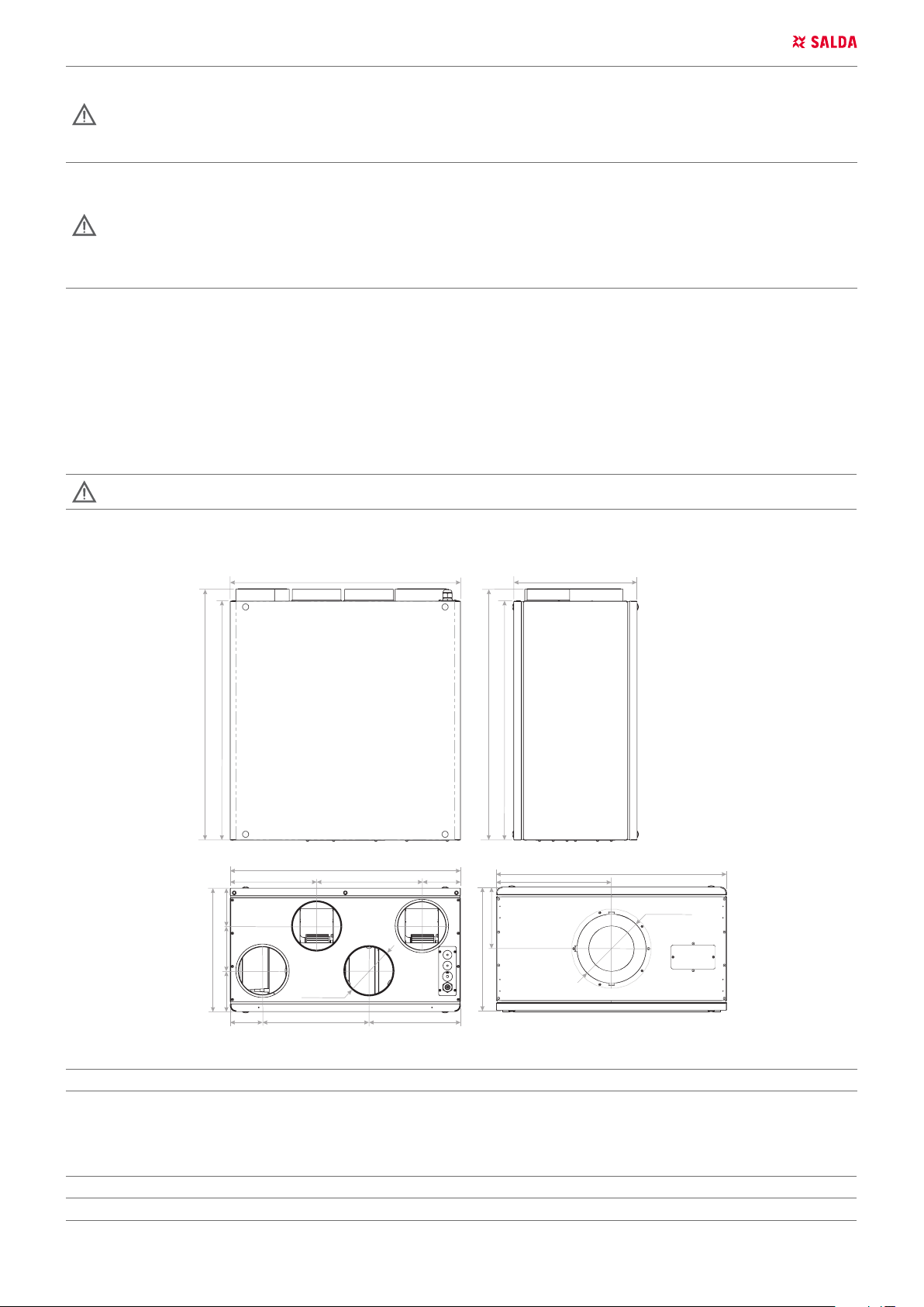
4.2. DIMENSIONS AND WEIGHT
620 mm
224,5 mm
98 mm
320 mm
116,3 mm
105,7 mm
84 mm
Ø 125 mm
276,3 mm
598 mm
598 mm
273,1 mm
237,7 mm
100,4 mm
653 mm
320 mm
160 mm
620 mm
286 mm
598 mm
Ø 175 mm
SMARTY
2R VER 2R VER PLUS
m [kg] 36 36
4.3. TECHNICAL DATA
SMARTY
Heat exchange
- phase/voltage [f/VAC/Hz] ~1/230/50 ~1/230/50
2R VER 2R VER PLUS
EN | 5SMARTY RV v2019.12

- power/current [kW/A] 0,006/0,1 0,006/0,02
-thermal eciency up to 75% 75%
Heater
- power/current [kW/A] 0,6/2,61 0,6/2,61
Exhaust air fan
- phase/voltage
- power/current
- speed
- protection class IP44 IP54
- control imput [VDC] 0-10 0-10
Supply air fan
- phase/voltage
- power/current
- speed
- protection class IP44 IP54
- control imput [VDC] 0-10 0-10
Total
- power/current [kW/A] 0,75/3,91 0,77/4,13
Automatic control integrated
Insulation of walls
Weight
Exhaust air lter
class class ePM10 55% ePM10 65%
width [mm] 270 270
height [mm] 86 85
depth [mm] 46 173
model MPL FMK
Supply air lter
class ePM10 55% ePM10 65%
width [mm] 270 270
height [mm] 86 85
depth [mm] 46 173
model MPL FMK
[f/VAC/Hz] ~1/230/50 ~1/230/50
[kW/A] 0,07/0,6 0,084/0,75
[min-1] 1380 3200
[f/VAC/Hz] ~1/230/50 ~1/230/50
[kW/A] 0,07/0,6 0,084/0,75
[min-1] 1380 3200
+ +
[mm] 20 20
[kg] 36 36
SMARTY 2R VER
Outdoor 62 22 54 61 48 41 27 20 14
Supply 70 29 61 68 59 60 55 49 43
Extract 62 22 54 61 49 36 28 19 14
Exhaust 69 28 60 67 58 58 52 48 41
Surrounding 49 10 40 48 36 31 30 30 29
Measured at 140 m3/h, 50 Pa
SMARTY 2R VER PLUS
Outdoor 60 18 50 58 55 44 28 16 12
Supply 66 23 55 63 61 56 55 48 40
Extract 60 19 50 58 54 40 35 24 17
Exhaust 66 23 55 62 60 56 53 46 36
Surrounding 48 3 34 44 45 32 31 30 29
Measured at 180 m3/h, 50 Pa
NOTE. Subject to technical modication
LWA TOTAL,
DB(A)
LWA TOTAL,
DB(A)
63 Hz 125 Hz 250 Hz 500 Hz 1 kHz 2 kHz 4 kHz 8 kHz
63 Hz 125 Hz 250 Hz 500 Hz 1 kHz 2 kHz 4 kHz 8 kHz
LWA, DB(A)
LWA, DB(A)
6 | EN SMARTY RV v2019.12
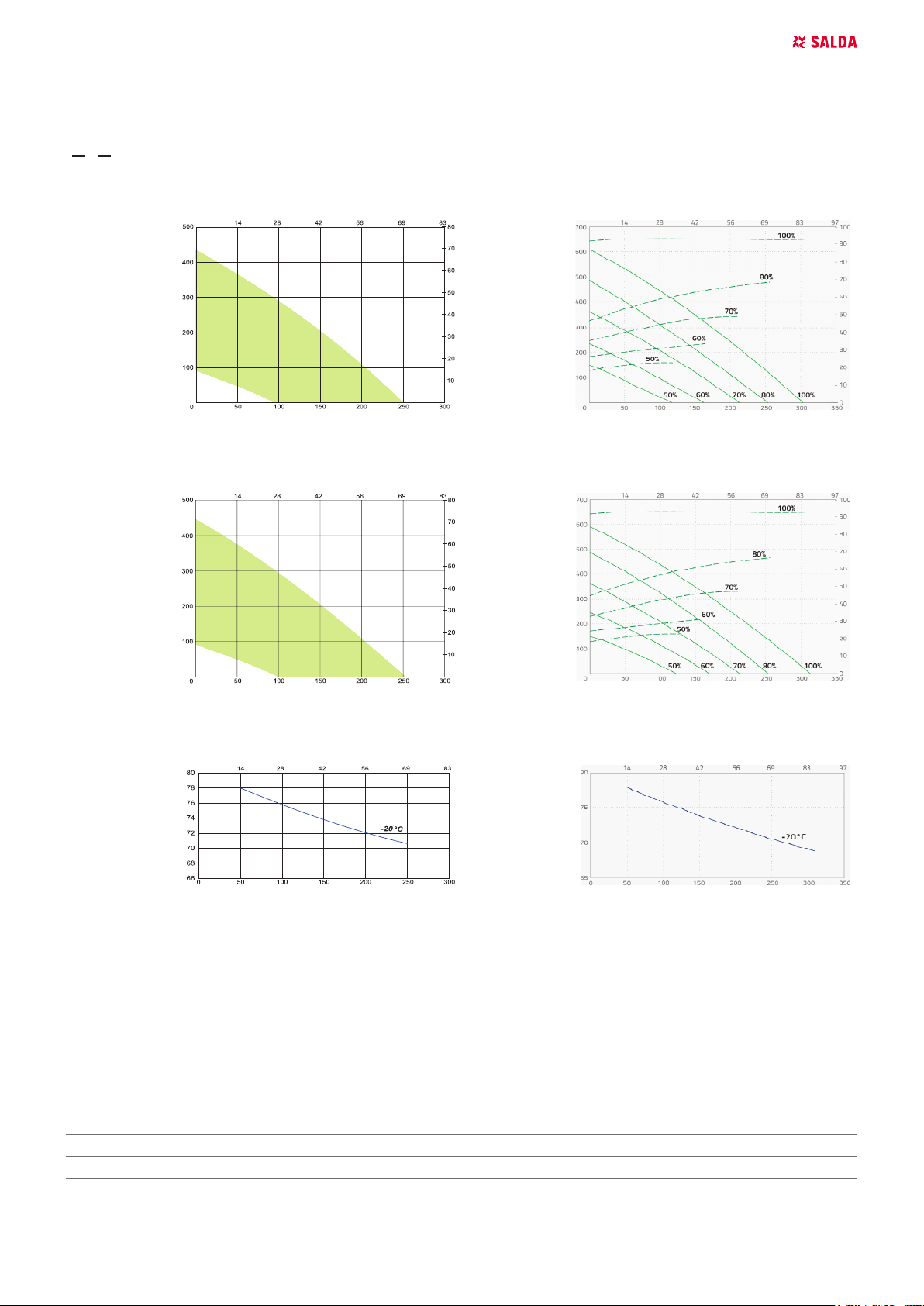
4.3.1. AIR FLOW DIAGRAMS
Performance
Power consumption
SMARTY 2R VER SMARTY 2R VER PLUS
Supply air Supply air
Exhaust air Exhaust air
Temperature eciency Temperature eciency
Temperature eciency (balanced mass ow):
Extract air = - 20 °C / 90 % RH
4.4. OPERATING CONDITIONS
• Unit is designed to operate only indoors.
• It is forbidden to use the unit in potentially explosive environment.
• Unit is designed to supply/extract only clean air (free of chemical compounds causing metal corrosion, of substances aggressive to zinc,
plastic and rubber, and of particles of solid, adhesive and bred materials).
OUTDOOR AIR
- temperature min./max.* [°C] -23 / +40
- humidity [%] 90
EXTRACT AIR
- temperature min./max.*
- max. humidity
[°C] +15 / +40
[%] 60
* Can be used at temperatures below -23 °C with pre-heater, the power of which is over 600W.
EN | 7SMARTY RV v2019.12
+40 C
10
9
10
9
o
+5 C
o
o
+40 C
o
-23 C
Figure 5.4.1 - operating conditions
4.5. STANDARD PACKAGE OF COMPONENTS
Standard package (without optional accessories) includes:
• Mounting brackets (mural and unit parts), Rubber seal for vibration damping.
• Screws M5x25 DIN7985 CT for mounting brackets - 3 pcs.; 5. Spring washers DIN127 5 - 3 pcs.
• Bushing caps - 8 pcs.
• Antivibration stick - 2 pcs.
• Key - 1 pcs.
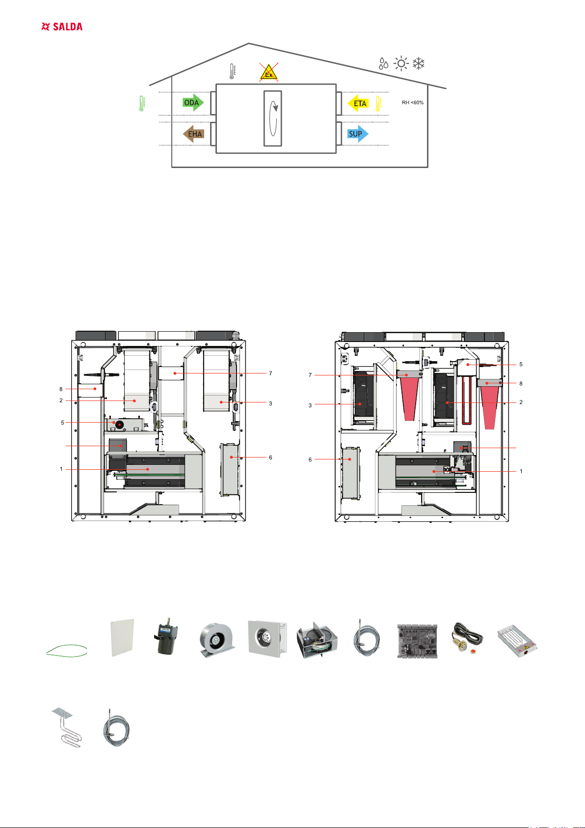
4.6. DESCRIPTION OF COMPONENTS
+40 C
+15 C
o
o
9
9
Figure 5.3.1 - Smarty 2R VER construction Figure 5.3.2 - Smarty 2R VER plus construction
1 - Plate/rotor heat exchanger; 2 - Supply fan; 3 - Exhaust fan; 4 - By-pass damper; 5 - Electrical/water heater/pre-heater; 6 - Control board; 7 -
Extract air lters (panel/pocket); 8 - Supply air lter (panel/pocket); 9 - Rotor motor.
4.7. SPARE PARTS
Rotor belt Door Rotor mo-
tor
Fan Fan Rotor box TJ MCB Hall H1A-
D12P24-1
SRR 0,6-1f
EC-1k
SRR V-0,6-
TL/TA
1f
8 | EN SMARTY RV v2019.12
Rotor box belt Rotor belt GNG00062
Smarty 2R VE door Door GNG00061
Rotor box motor Rotor motor ZVAR0133
Fan supply/exhaust
Fan
(Smarty 2R VER)
Fan
(Smarty 2R VER plus)
GPUVRA009
GVESMARTY001
Rotor box Rotor box GPURSD085_330
Temperature sensor 3 m TJ PJUT0063
Temperature sensor 1,5 m TL/TA PJUT0062
Controler MCB V1.0 ZED00985
Hall sensor Hall H1A-D12P24-1 PJUT0006
Electrical heater
SRR 0,6-1f EC-1k
(Smarty 2R VER)
SRR V-0,6-1f
(Smarty 2R VER plus)
ZESSRR028
ZESSRR032
5. INSTALATION
5.1. RECEPTION OF GOODS
Each device is thoroughly checked before transportation. When receiving goods it is recommended to check whether devices were damaged
during transportation. If damage to the device is identied, immediately inform the representatives of a transport company. Please inform a representative of the manufacturer, if any deviation from the order is noticed.
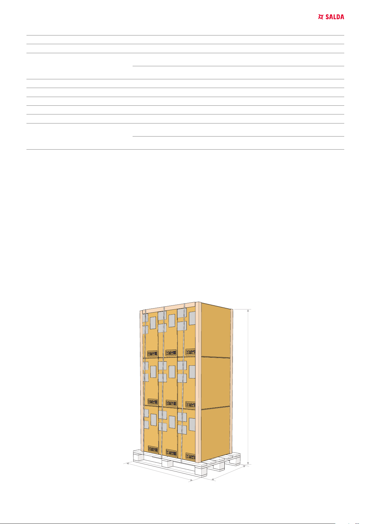
5.2. TRANSPORTATION AND STORAGE
• All units are packed in the factory to withstand regular conditions of transportation.
• Upon unpacking, check the unit for any damages caused during transportation. It is forbidden to install damaged units!!!
• The package is only for protection purpose!
• While unloading and storing the units, use suitable lifting equipment to avoid damages and injuries. Do not lift units by holding on power sup-
ply cables, connection boxes, air extract or exhaust anges. Avoid hits and shock overloads. Before installation units must be stored in a dry
room with the relative air humidity not exceeding 70% (at +20 °C) and with the average ambient temperature ranging between +5 °C and +30
°C. The place of storage must be protected against dirt and water.
• The units must be transported to the storage or installation site using forklifts.
• The storage is not recommended for a period longer than one year. In case of storage longer than one year, before the installation it is necessary to verify whether the bearings of fans and motor rotate easily (turn the impeller by hand) and if the electric circuit insulation is not damaged
or the moisture is accumulated.
2020 mm
1200 mm
780 mm
EN | 9SMARTY RV v2019.12
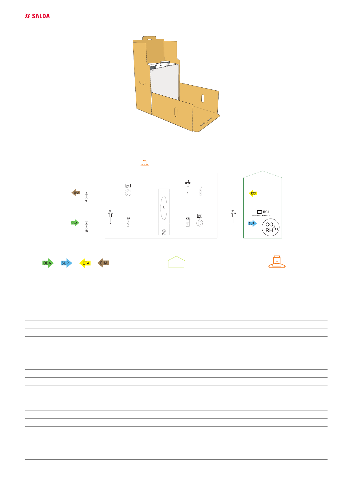
5.3. UNPACKING
M
CO
2
5.4. MOUNTING DIAGRAM
Figure 5.4.1 - Smarty RV (** Only one sensor can be used at a time)
Figure 5.4.2 - Indication for duct connection. Figure 5.4.3 - Ventilated premises Figure 5.4.4 - Air from cooing hood
LIST OF COMPONENTS
C Plate heat exchanger A1 Fire alarm damper actuator I
PV Supply air fan A2 Fire alarm damper actuator II
IF Extract air lter TJ Supply air temperature sensor
PF Supply air lter TL Outdoor air temperature sensor
IV Exhaust fan TE Exhaust air temperature sensor
KE1 Electric heater DTJ Extract air temperature and RH sensor
PE1 Electric pre-heater T2 Cooler changeover thermostat
KV2 Water pre-heater TV2 Water preheater temperature sensor
KV3 Water cooler TV3 Water cooler temperature sensor
DX DX cooler U3 PV pressure transmitter
M1 By-pass damper U4 IV pressure transmitter
M2 Outdoor air damper actuator CO
M3 Exhaust air damper actuator RH RH sensor*
M5 Water cooler valve motor PC Computer
M12 Water pre-heater valve actuator RC1 Stouch or SA-Control remote control panel
M14 Water cooler circulation pump RC2 Stouch, Flex or SA-Control remote control panel
M15 DX cooler valve actuator MB-Gateway Network module
M16 Water pre-heater circulation pump NET Network
R Rotor heat exchanger
2
CO2 sensor*
10 | EN SMARTY RV v2019.12
POSSIBLE PCB INPUTS/OUTPUTS
FA Fire alarm H1 Working indication output
FPP Fireplace protection H2 Alarm indication output
System mode switch (START/STOP) Fans speed switch (BOOST)
* Compone
5.5. MOUNTING
• Installation should only be performed by qualied and trained sta.
• When connecting air ducts, consider the notices indicated on the casing of the unit.
• Before connecting to the air duct system, the connection openings of ventilation unit should be closed.
• Do not connect the bends close to connection anges of the unit. The minimum distance of the straight air duct between the unit and the rst
branch of the air duct in the supply air duct must be 1xD, in air exhaust duct 3xD, where D is diameter of the air duct.
• It is recommended to use the accessories-holders. This will reduce vibration transmitted by the unit to the air duct system and environment.
• Enough space must be left for opening of the maintenance door and lter covers.
• If the installed ventilation unit is adherent to the wall, it may transmit noise vibrations to the premises. Though the level of noise caused by the
fans is admissible, it is recommended to mount the unit at the distance of 400 mm from the nearest wall. If it is not possible, the mounting of
the unit is recommended on the wall of the room where the level of noise is not important.
• Ducts are connected to the unit in such way that they could be easily disassembled and the heater could be removed from the unit when
performing service or repair works.
5.5.1. MOUNTING ON THE WALL
90
90
30 mm
a c d
b
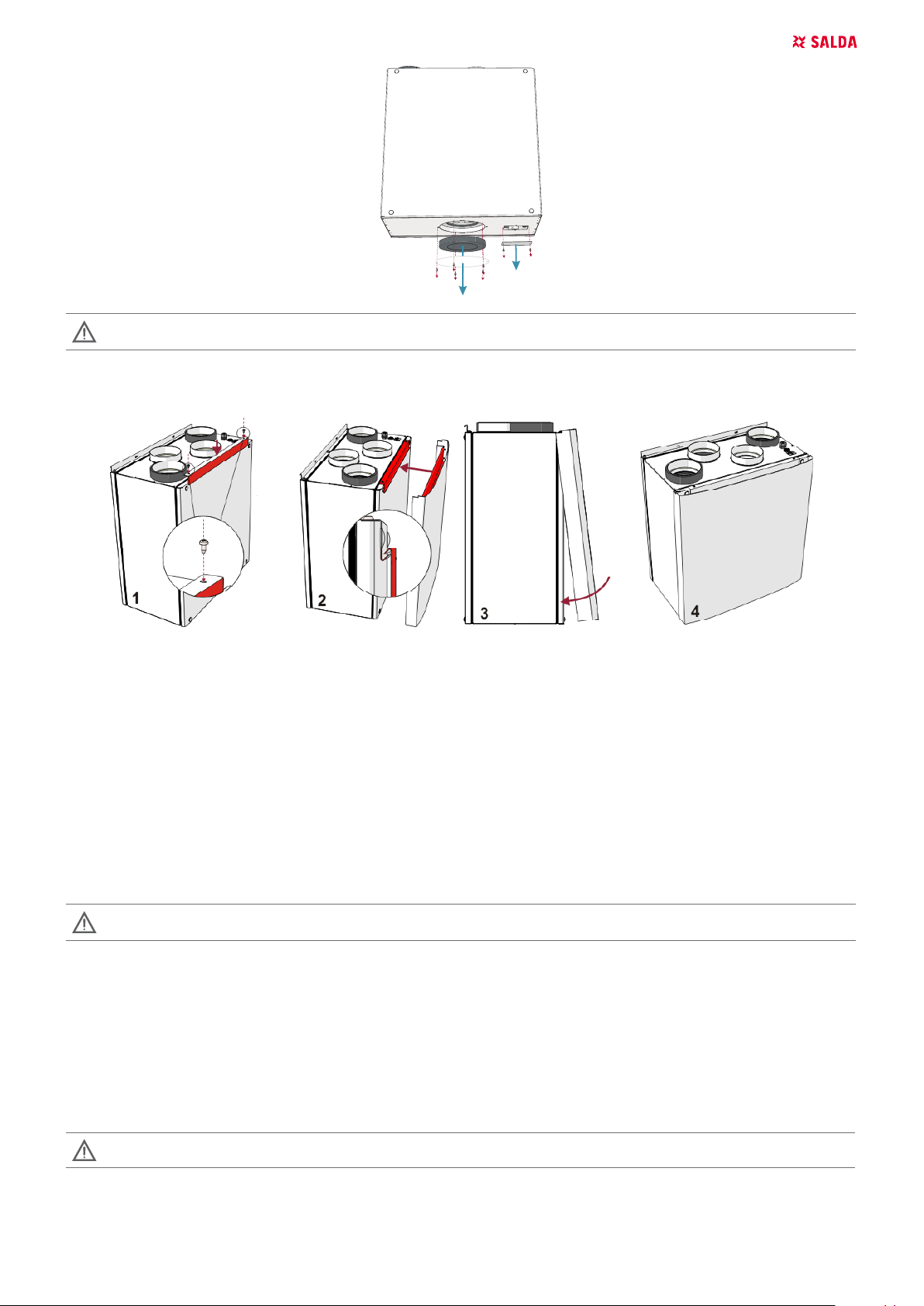
Mounting on the wall:
a) To reduce the vibration stick the insulating tape on the unit‘s casing side which touches the wall before mounting the unit on the wall.
b) The unit has to be mounted on the mounting brackets.
c) AHU mounting drawing.
d) After the unit is mounted two wall bracket tabs has to be folded to 90o angle by pliers to avoid the accident fall of the unit.
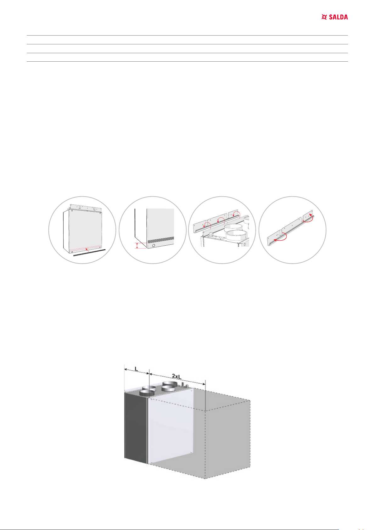
5.5.2. PLACE REQUIREMENTS FOR THE EQUIPMENT AND MOUNTING POSITIONS
1. The installation position only in the horizontal direction.
2. Install the supporting legs.
3. AmberAir Compact are assembled from separate sections.
4. They must be adjusted without a gradient.
5. Leave space in the front (2xL) that it would be sucient to open the doors and to remove or install a required component.
EN | 11SMARTY RV v2019.12
5.5.3. CONNECTION OF AIR DUCTS
• Connected air ducts must be straight and have their own xing.
• Make sure that the fans can not be accessed through air duct heads. If it is possible to access the fan, protective grid should be installed. You
can choose it in our website.
• Do not reduce the diameter of the piping near air inlet or exhaust ducts. If you want to reduce the speed of air in the system, drop of pressure
and noise level, you can increase the diameter.
• In order to reduce the level of the noise in the air supply system, install silencers (see chapter on their installation).
• In order to reduce air loss in the system, the air ducts and prole parts should be of class C and higher. Their catalog can be found in our
website.
• If air handling unit is installed in heated premises, outdoor and exhaust air ducts must be insulated in order to avoid heat loses and condensing.
If AHU is installed outdoors, it’s recommended to insulate all the air ducts.
• It is recommended to maintain a distance of up to 8 meters between air intake and air exhaust ducts. Air supplying system should be installed
further from potential air pollution sources.
• Use holders while installing air ducts next to the ventilation equipment. They suppress vibration and ensure a rm installation of various system
parts.
• Necessary holders can be found in our catalog or website.
• A common mistake is that air ducts are attached to improper airow connection. On the ventilation equipment there are signs, indicating the air
duct to be connected. Before starting the system carefully check whether the work was performed properly.
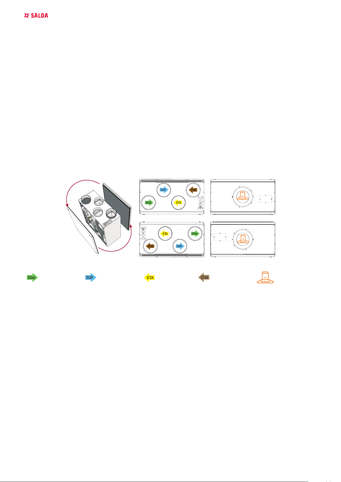
5.5.4. AIR FLOW
The maintenance side can be changed for the ventilation unit, i.e. it can be mounted with the left ambient air inlet or the right ambient air inlet. That
can be implemented by switching over the back door and the front door. The default version of the ventilation unit is right.
Converted service side to Left version
Standard version (Right)
outdoor air supply air extract air exhaust air kitchen hood
5.5.5. CONNECTION OF THE KITCHEN HOOD
• Installation works must be performed only by trained and qualied personnel.
• If you have any questions regarding the save installation and use of the product, please contact the manufacturer or the representative.
• Before installing the unit, unscrew the lid a covering the opening for connection of the kitchen hood and remove the middle part of the insulating ring.
• Cut the connecting opening as indicated on the insulation material.
• Carefully remove the lid, which covers the electric connection for the connection of the electrical part of the kitchen hood to the ventilation unit.
• Mount the hood to the ventilation unit. Fasten with self-tapping screws to the designated connection points.
• It is necessary to ensure the tight and reliable connection of the air ducts of the kitchen hood to the ventilation unit and the electrical contact
of the control circuit.
• The subsequent installation of the device is performed according the description in chapter “Mechanic installation”.
• Properties, assembly, control, use and maintenance of the kitchen hood are described in its instalation manual.
12 | EN SMARTY RV v2019.12
Use cooker hood supplied by our company only. Equipment is not tested with other cooker hoods and company holds no
responsibility for malfunction or failures of the equipment in this case.
5.5.6. SHIELD INSTALLATION
5.6. CONNECTION OF THE UNIT TO ELECTRIC NETWORK
• Supply voltage to the unit must be connected by a qualied specialist following the manufacturer’s instructions and eective safety instructions.
• The unit’s power network voltage must correspond to electrotechnical parameters of the unit indicated in the technical decal.
• The unit’s voltage, power and other technical parameters are provided in the unit’s technical decal (on the unit casing). The unit must be con-
nected to the voltage plug socket of the grounded power network in compliance with the eective requirements.
• The unit must be earthed according to the rules on installing electrical equipment.
• It is prohibited to use extension wires (cables) and power network plug socket distribution devices.
• Prior to carrying out any ventilation unit installation and connection activities (until its hand-over to the customer), the unit must be disconnected from the power network.
• After installation of the ventilation unit, the power network plug socket must be accessible at any time and disconnection from the power network is performed through the two-pole circuit breaker (by disconnecting phase pole and neutral).
• The unit must be thoroughly checked against damages (execution, control, measurement nodes) during transportation before it is connected
to the power network.
• The power cable can be replaced only by a qualied specialist upon the evaluation of the rated power and current.
The manufacturer does not assume any liability for personal injuries and property damage due to non-conformance with
the provided instructions.
5.7. START-UP RECOMMENDATIONS
5.7.1. SYSTEM PROTECTION
Control system of the unit has an integrated protection against short-circuit for these functional components. The controllers have the following
protections:
MCB
F1, F2 - 1A(5x20) MCB protection
To ensure safe maintenance of the unit, it is necessary to remove the plug from the power network.
EN | 13SMARTY RV v2019.12
5.7.2. PRE-STARTUP RECOMENDATIONS OF THE UNIT (IN THE PRESENCE OF THE ENDUSER)
Prior to start-up the system must be thoroughly cleaned. Check whether:
• operation systems and unit elements as well as automation and automation devices were not damaged during installation,
• all consumers are connected to power supply and t for service,
• all necessary automation elements are installed and connected to power supply and MCB terminal blocks,
• cable connection to MCB terminal blocks comply with the existing power connection diagrams,
• all electrical equipment protection elements are properly connected (if they are additionally used),
• cables and wires correspond to all applicable safety and functional requirements, diameters, etc.,
• earthing and protection systems are properly installed,
• condition of all seals and sealing surfaces is proper.
6. MAINTENANCE
Unplug unit from mains before opening the door (disconnect the power plug from the outlet or if there is a two-pole automatic
circuit breaker installed – disconnect it as well. It is necessary to ensure that it won’t be turned on by third parties) and wait
until the full stop of the fans (for about 2 min.).
6.1. SAFETY INSTRUCTION
• Do not use the unit for purposes other than its’ intended.
• Do not disassemble or modify the unit in any way which may lead to mechanical failure or injury.
• Use special clothing and be careful while performing maintenance and repair jobs – the unit’s and its components’ edges may be sharp and cutting.
• Do not wear loose clothing that could be entangled in to operating unit.
• If a outside object enters the unit, immediately disconnect power source. Before removing object, make sure that any mechanical motion has
stopped, the heater has cooled down and the restart is not possible.
• Do not connect to any other power source than indicated on the model label.
• Do not place or operate unit on unsteady surfaces and mounting frames.
• Mount the unit rmly to ensure safe operating.
• Never use this unit in the environment containing any explosive or aggressive elements.
• Do not use the unit if external connections are broken or damaged. If there are any defects, stop operating the unit and replace the damaged parts
immediately. That can be performed only by qualied electrician.
• Do not use water or another liquid to clean electrical parts or connections.
• If you notice condensat on electrical parts or connections, stop operating the unit.
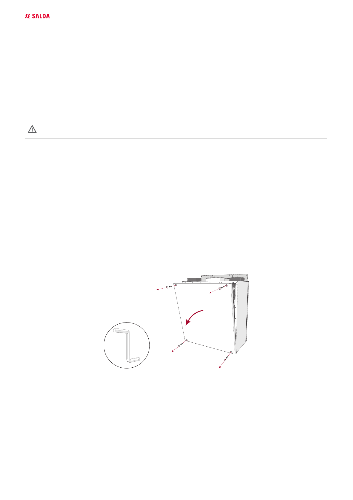
6.2. COVER OPENING
14 | EN SMARTY RV v2019.12
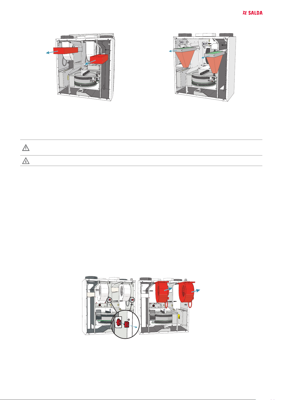
6.3. FILTERS MAINTENANCE
Figure 6.3.1 - Smarty 2R VER Figure 6.3.2 - Smarty 2R VER plus
Dirt increases air resistance in the lter, therefore less air is supplied into the premises.
Taking o the lters:
• Open cover.
• Remove the lter.
Changing lters, lters reload timer control. Description of remote control panel functions is provided in the remote control
panel technical documentation or on the website www.salda.lt.
Allowed to operate the unit without lters!
It is recommended to change the lters every 3-4 months, or in accordance to lter timer.
6.4. FANS MAINTENANCE
• Maintenance should be performed only by experienced and trained sta.
• The fan should be inspected and cleaned at least once a year.
• Be sure the fan is disconnected from power source before performing any maintenance or repair.
• Proceed to maintenance and repair after any rotation in the fan is stopped.
• Observe sta safety regulations during maintenance and repair.
• The motor is of heavy duty ball bearing construction. The motor is completely sealed and requires no lubrication for the life of the motor.
• Detach fan from the unit.
• Impeller should be specially checked for buil-up material or dirt which may cause an imbalance. Excessive imbalance can lead to accelerated
wear on motor bearings and noise, vibration.
• Clean impeller and inner housing with mild detergent, water and damp, soft cloth.
• Do not use high pressure cleaner, abrasives, sharp instruments or caustic solvents that may scratch or damage housing and impeller.
• Do not plunge the motor into any uid while cleaning impeller.
• Make sure, that impeller ’s balance weights are not moved.
• Make sure the impeller is not hindered.
• Mount the fan back into the unit. Connect the fan to power supply source.
• If after maintenance the fan does not start or stop itself, contact the producer. Malfunction of the fan can be identied according to the pressure
in the system (when pressure switches are connected). When there is a fault in fans’ motor, any separate notice is shown on the control panel.
Figure 6.4.1 - Smarty 2R VER
EN | 15SMARTY RV v2019.12
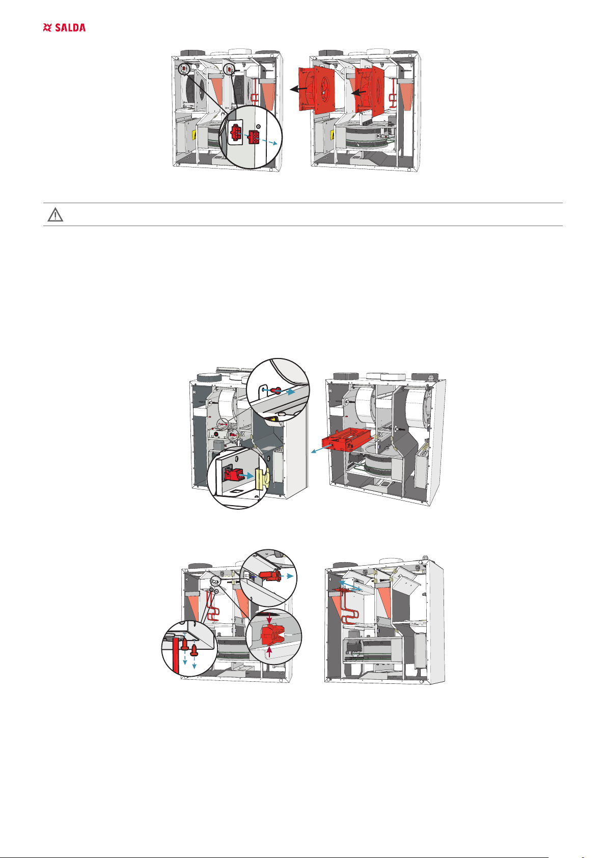
Figure 6.4.2 - Smarty 2R VER plus
Be sure the unit is disconnected from power source before performing any maintenance or repair.
6.5. HEATER MAINTENANCE
• Electrical heater does not need to be serviced additionally. It is compulsory to change lters as described above.
• Heaters have 2 thermal protections: automatically self-resetting, which activates at +50°C and the manually restored, which activates at
+100°C.
• After the activation of the manually restored protection, the unit must be disconnected from the power supply. Wait until the heating elements
cool down and the fans stop rotating. After identifying and removing the reason of failure, to start the unit, press the “reset” button. The failure
can be identied only by a qualied professional.
• If necessary, the electric heater can be removed. Disconnect the electrical connector from the heater and remove the heater.
Figure 6.5.1 - Smarty 2R VER
1
a
b
a
2
3
Figure 6.5.2 - Smarty 2R VER plus
6.6. ROTOR MAINTENANCE
• Rotor heat exchanger must be serviced once a year.
• Ensure that the gaps of the heat exchanger are clean, the brushes are not worn, the belt drive is not worn and the clamping nodes of the rotor
heat exchanger are tight.
• Rotor heat exchanger can be easily removed from the unit. The power cord of the motor of the heat exchanger is disconnected. The clamp of
rotor heat exchanger section is released and raised and the heat exchanger is removed.
• The heat exchanger is cleaned using the solution of warm water and non-corrosive toward aluminum alkaline agent or the air stream. It is not
recommended to apply direct stream of liquid as it can harm the device.
16 | EN SMARTY RV v2019.12
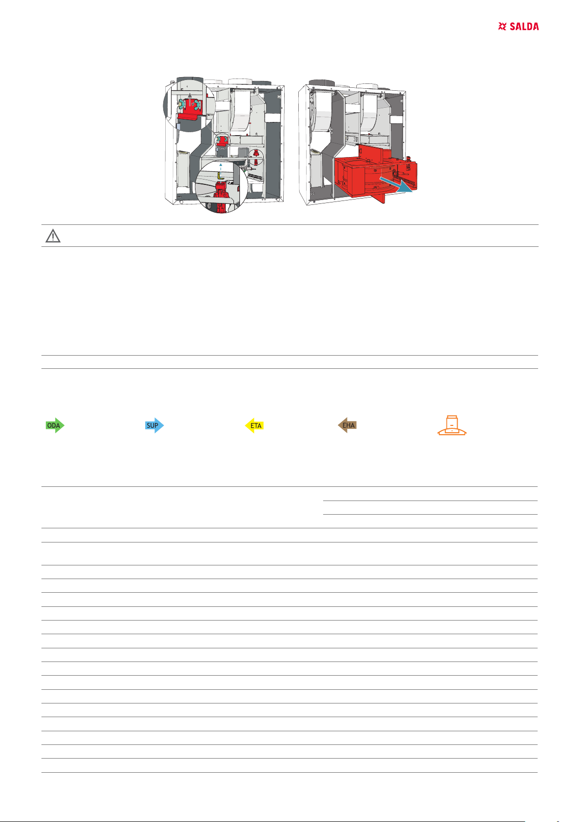
• While cleaning, protect the motor of heat exchanger from entry of moisture and uids.
• After reinstalling the heat exchanger, fasten the heat exchanger section with the clamp. Connect the heat exchanger motor.
CAUTION: the heat exchanger can not be used when the lters are removed!
7. CONTROL
7.1. DEVICE CONTROL
Ventilation unit can be controlled using a remote control, web interface via MB-Gateway and building management system. More information about
the possibilities of controlling is provided in the table below.
MB-Gateway + WIFI + SALDA AIR app Stouch FLEX MCB SA-Control MB-Gateway BMS
+ + + + + Modbus RTU
7.2. MEANING OF THE SYMBOLS USED IN THE INSTRUCTIONS AND ON THE DEVICE
outdoor air supply air extract air exhaust air kitchen hood
7.3. DESCRIPTIONS OF THE FUNCTIONS
MCB
Functions
Date and time settings
System modes for easy and-user friedly control (Stand-by, Building protection,
Economy, Comfort)
BOOST function (Fans operate at highst speed)
Comfortable air temperature function
Cold/heat recovery
Heating season (from a selected date, 3-day temperature average or manually)
Dryness protection
Weekly/holiday schedule
User and service control levels
Manual air ow balancing
CO2 level indication and reduction function
Night cooling function
Relative humidity (RH) level indication and reduction function
Software and conguration update possibility
Supply air temperature control according to the extract air sensor
Monitoring function (all sensors and I/O) Mode switch (start/stop)
Manual components control
Smarty 2R VER Smarty 2R VER plus
E E
● ●
● ●
● ●
● ●
● ●
● ●
○ ○
● ●
● ●
● ●
○ ○
● ●
○ ○
● ●
● ●
● ●
● ●
EN | 17SMARTY RV v2019.12

Functional units
Fans
Speed synchronous/asynchronous 0-10V control
Electrical heater
Overheat protection (additional protection software)
Filter pollution minitoring
Rotor
Air temperature sensors
temperature sensor failure protection (with emergency mode)
Dampers
Emergency signals and inputs/outputs
Remote controllers
Switching the speed of the fans
Soft start and stop
Protection by RPM
On/o control
By lter timer
On/o control
Motor belt levers protection
Rotation speed indication
Service timer
Supply air temperature sensor
Outdoor air temperature sensor
Extract air temperature sensor
open/close
Fire protection input ● ●
Congurable digital inputs ● ●
Stouch ○ ○
SA-Control
MB Gateway
● ●
● ●
● ●
● ●
● ●
● ●
● ●
● ●
● ●
● ●
● ●
● ●
● ●
● ●
● ●
○ ○
○ ○
○ ○
● standard feature
○ for the feature to function an accessory is needed
- it is not possible to use the feature
7.4. DESCRIPTION OF THE UNITS FUNCTIONS
All functions indicated in this section are installed in the software of the control board. However, operation and control of the device depends on
the following:
1. Selected control panel. Full functionality and conguration possibility can be assured only by MB-Gateway web interface SA-Control, SALDA
AIR app.
2. Connected external devices: external heaters, dampers, sensors and etc. (see the description of the acquired air handling system).
3. Internal components of the device: type of heat exchanger (plate or rotor), integrated dampers, sensors and etc. (see components of the
chosen device).
4. Control board type.
Air Handling Unit uses MCB board.
The unit can be congured only with SA-Control remote con trol panel, MB-Gateway web application or SALDA AIR app.
The following control board functions can be fully con trolled only with SA-Control remote con trol panel, MB-Gateway web
application or SALDA AIR app. In case of Stouch remote con trol panel use the description of remote control panel functions
for MCB control board.
7.4.1. SYSTEM MODES
• Stand-by;
• Building protection;
• Economy;
• Comfort.
18 | EN SMARTY RV v2019.12

In Stand-by mode the system is shut down for a permissible period (based on the Stand-by mode blocking function settings).
The Building protection mode is designed to protect premises against moisture accumulation. The system operates at speed 1. Based
on manufacturer’s parameters (by default) this mode controls the temperature (the desirable one is indicated), but, if necessary, it can
be switched o, i.e. to activate the energy saving mode. Also, if necessary, full recirculation function is activated. (ADJUSTER › USER SETTINGS
› BUILDING PROTECTION MODE TEMPERATURE or USER › MENU › SETTINGS › BUILDING PROTECTION).
After activating the energy saving mode, temperature is maintained only by the heat exchanger. It will seek to maintain the current
temperature in the room; however, if the supply air temperature falls below the minimal supply air temperature level, heaters will be
activated and they will maintain a temperature one degree above the minimum. Also, if the supply air temperature rises above the
maximal supply air temperature level, coolers will be activated and they will maintain a temperature one degree below the maximum.
Economy mode is designed to save energy when people are absent from the premises. The system operates at speed 2. Based on
manufacturer’s parameters this mode controls the temperature maintaining (the desirable one is indicated), but, if necessary, it can
be switched o, i.e. to activate the energy saving mode. Also full recirculation function is activated. (ADJUSTER › USER SETTINGS › ECONOMY MODE
TEMPERATURE or USER › MENU › SETTINGS › ECONOMY MODE).
Comfort mode is running when people are present in the premises. The system operates at speed 3. In this mode the temperature is
always maintained – it is set in the main window (ADJUSTER › VENTILATION CONTROL or USER › SET POINT).
7.4.2. SYSTEM CONTROL
System modes are changed by the following functions (indicated in a sequential order):
• Weekly Schedule;
• Switching on is activated from an external contactor;
• Manual mode selection;
• Holiday Schedule;
• Stand-by mode blocking.
Based on the Weekly Schedule the system decides in what mode it will be operating; however, the user may change it manually. The system
informs when the next mode change is scheduled. After power loss the mode is selected based on the Weekly Schedule; however, if it is not set,
the mode that was set before the power loss will be activated.
The user may change modes even when the switching on is activated from an external contactor. The only case when it is not possible – active
period of Holiday Schedule of which the system informs and which must be changed to avoid blocking.
Stand-by mode can be blocked by selected parameters. If at least one of the above functions changes its mode into Stand-by mode, it must be
checked whether this mode is not currently blocked. If it is blocked, the previous mode shall be activated.
The function order is provided below.
Start
› Reading of input data;
› Weekly Schedule;
› Mode external switch;
› User entered data;
› Holiday Schedule;
› Stand-by mode schedule;
› Stand-by mode blocking;
› Protection against Dryness;
› Boost ventilation;
› Air handling unit operating algorithm;
End
› Protection;
› Blocking of air handling unit operating algorithm;
› Manual Control of Components;
› Data entering into outputs and user environment.
EN | 19SMARTY RV v2019.12

7.4.3. SYSTEM STATES
This eld informs a user about the existing system state. It is displayed in the main window ADJUSTER › VENTILATION CONTROL or the main window of the user
environment. The table below shows possible system states.
SYSTEM STATE DESCRIPTION
Stand-by mode System operates in Stand-by mode
Building protection mode System operates in Building protection mode
Economy mode System operates in Economy mode
Comfort mode System operates in comfort mode
Emergency run System operates in emergency mode (for details refer to alarms section)
Preparing System is preparing for operation (pre-heating of water heaters, etc.)
Opening dampers Dampers are opened
BOOST function activated BOOST function is active
Cooling heaters Electric heaters are cooled down prior to shutdown of fans
Closing dampers Dampers are closed
Critical alarm Critical failure, system is shut down (for details refer to alarms section)
Fire alarm Fire protection from an external contactor is activated
Heat exchanger frost protection activated Heat exchanger frost protection is activated
Change lters Warning about clogged lters (pressure switches are activated or lter timer is
Room RH 3 days average is lower than 30%. Limiting speed.
DX cooler defrosting
Fire damper testing
activated)
Reduced airow because of too low exhaust air moisture
Dissolving the DX cooler / heater
Checking re dampers
7.4.4. SETTING DATE AND TIME
For smooth execution of schedules, event log and winter/summer function, it is necessary to set proper date and time in section ADJUSTER › USER SETTINGS
› DATE AND TIME SET and click a button DATE AND TIME SET. It can also be indicated in user environment USER › MENU › SETTINGS › DATE AND TIME. Fast synchronization
with the computer time is possible in user and adjuster environment.
7.4.5. SUPPLY AIR TEMPERATURE CONTROL AND COMPENSATION
Temperature for supply air or premises temperature may be indicated. In the service environment section SERVICE › MAIN › SUPPLY AIR TEMPERATURE CONTROL you
can control it based on supply or exhaust air temperature. If control by premises temperature is selected, then it is calculated what kind of air is to
be supplied so that the proper room temperature is maintained. It is limited by allowable limits of supply air temperature.
The air handling unit is not designed to heat premises, therefore it is not necessary to use full capacity for low temperature dierences – the
compensation in percentage is provided for this purpose. This parameter indicates a percentage of the temperature dierence (between the set
temperature and premises temperature) to be compensated for by this function. E.g. set point is 20 °C, temperature in the premises is 16 °C,
compensation is 50 %, dierence between the indicated and existing temperatures is 20-16=4 °C. Since 50 % is compensated, then 4*50 %=2
°C. When the received value is added to the set temperature we get the required supply air temperature – 2+20=22 °C. This temperature is not
limited as it is within the supply air temperature protection limits. In this case the system maintains the supply air temperature at 22 °C. The closer
the premises temperature is to the set temperature (20 °C), the faster the supply air temperature reaches 20 °C.
It may be too hot in the premises, therefore this function both heats and cools. Preferred (compensated) temperature is displayed in the window
MONITORING (REQUIRED SUPPLY). If the displayed temperature is 0 °C, it means that temperature maintaining of supply air is switched o.
The temperature of supply air is maintained by the following components (indicated in a sequential order):
• Fans (operate slower, if it is too hot);
• Recirculation valve (if the ambient air temperature is favourable);
• Water cooler;
• DX cooler;
• Recirculation damper and CO2 (in case of favorable outdoor temperature);
• Bypass damper or rotor (in case of favorable outdoor temperature);
• Recirculation damper and CO2 (in case of favorable outdoor temperature);
• DX heater;
• Water heater;
• Water cooler/heater;
• Electrical heater;
• Fans (operate slower, if it is too cold).
Firstly the system tries to maintain the supply air temperature by means of a heat exchanger. In case of a plate heat exchanger, the bypass damper
is controlled, and in case of a rotary heat exchanger, the rotor rotating speed or interval is changed. The heat exchanger can both heat and cool –
it depends on outdoor and room air temperatures. It is controlled by a PID controller whose coecients are indicated in the adjuster environment
section ADJUSTER › PID CONTROLLERS ADJUSTING › HEAT EXCHANGER CONTROL BY SUPPLY AIR TEMPERATURE.
When the heat exchanger operates at full capacity and preferred temperature is not reached, the recirculation damper, then the heater or cooler
etc. is activated (if necessary). Only the components congured for temperature maintaining are activated. It takes 10 s for the system to switch
20 | EN SMARTY RV v2019.12

between the elements.
7.4.6. FAN CONTROL
The preferred air-ow can be indicated in percentage or in 4 xed speeds where each of them is dedicated to a relevant system mode:
• Building protection;
• Economy;
• Comfort;
• Maximum power.
Fan speed can be controlled by:
• Percentage - speed in percentage is indicated in the adjuster environment window ADJUSTER › AIR FLOWS ADJUSTING: 0 % corresponds to 0, and 100
% – 10 V control signal voltage;
• Pressure - the maximum system pressure is indicated, which based on speed settings in the adjuster environment ADJUSTER › AIR FLOWS ADJUSTING
means 100 % air-ow;
• Air-ow (m3/h) - K factors of supply and exhaust air and the maximum system air-ow (m3/h) are displayed, which based on speed settings in
the adjuster environment ADJUSTER › AIR FLOWS ADJUSTING means 100 %.
Fans based on air-ow and pressure are controlled by PID controller and its coecients are indicated in the adjuster environment section ADJUSTER
› PID CONTROLLERS ADJUSTING › FANS SPEED CONTROL BY AIR FLOW OR PRESSURE. Each fan is controlled individually.
In the service environment window SERVICE › FANS › FANS SPEED CONTROL you can limit the minimum and maximum fan control signal voltage. Based on
manufacturer set parameters, the minimum 2V voltage is indicated, which means that 0V voltage signal is sent when fans are o, and 2V voltage
signal is immediately switched on when rotation is required.
It is possible to specify the nominal ows of supply and exhaust air. Then, the maximal air ow is calculated automatically.
7.4.7. “BOOST“ FUNCTION
Boost ventilation function is used for fast ventilation of premises. It activates the maximum air-ow (speed 4). Boost ventilation has be temporary,
i.e. it must be a nal condition (e.g. CO2 limit, time). The reason for this limitation – protection against dryness. High air ow reduces humidity, and
dry air is harmful for health.
The function is activated by pressing ON and deactivated by pressing OFF button in the BOOST section, or by means of an external contactor
(FANS SPEED SWITCH), which is congured in the service environment (SERVICE › MAIN › FANS SPEED SWITCH) section.
The function is inactive when Stand-by mode is on. Time limit is indicated (ADJUSTER › USER SETTINGS › BOOST TIMER or USER › MENU › SETTINGS › BOOST TIMER). Once the
function is activated, the time is set by the timer and the time is counted till its deactivation. It may be adjusted in real-time, i.e. when the function
is on, in ADJUSTER › VENTILATION CONTROL or in the user environment main window.
7.4.8. WEEKLY SCHEDULE
A weekly schedule consists of 10 weekly events. They can be added, deleted, activated and deactivated. One event indicates time, mode/BOOST
function, days of the week. Also it is possible to indicate the change of settable mode temperature.
The system changes modes according to the Weekly Schedule only at the indicated times, therefore a user can always change the existing mode
manually. This schedule noties of the upcoming mode change by indicating the time remaining till the next event.
The schedule is edited in user environment USER › MENU › SCHEDULE.
7.4.9. HOLIDAY SCHEDULE
This schedule is used when the unit has to operate in uniform mode during holidays. The user interface shows when the schedule period is active
as nobody can change the mode activated by this function (except for protection). In order to control the system in a normal manner, the Holiday
Schedule period must be deactivated, i. e. zero values must be indicated or dates must be changed. Up to ve holiday periods can be set.
The schedule is edited in the user environment USER › MENU › HOLIDAY.
7.4.10. WINTER/SUMMER MODE
The winter/summer function is set during the cold periods, because some parts of the system have to be protected against cold outdoor air. During
winter it is recommended to leave the unit switched on, therefore it is possible to set blocking of switch-o. Water heaters must always be switched
on during the entire winter.
The winter mode may be indicated
• Manually;
• By date;
• Based on 3-day mean outdoor temperature, to be calculated only when the fresh air (outdoor) pre-heater is o.
7.4.11. DRYNESS PROTECTION
This function is designed to protect premises against dryness. If the function is active, it calculates the 3-day mean humidity of extract air from the
premises. If the mean drops below set limit (30%), fans start operating in speed 2 in comfort mode. A user is notied of the activated protection
and limited air ow.
If the humidity mean exceeds set limit (30%) or the function is switched o manually, fans start operating in speed 3 in comfort mode.
The function is switched on/o in the section ADJUSTER › USER SETTINGS › DRYNESS PROTECTION or in the window USER › MENU › SETTINGS › OTHER.
EN | 21SMARTY RV v2019.12

7.4.12. NIGHT COOLING FUNCTION
This function is designed to save energy in the morning, when a fresh night air is used to cool down the building. The function is active only in
summer. If it is switched on but not active yet, activation conditions are checked:
• System time from function start to the end (hours/minutes);
• Time is exactly every hour from the start;
• If STAND-BY mode is set, the unit operates in BUILDING PROTECTION mode for 5 minutes so that the actual temperature data is available. The temperature is checked after purging. If it is not suitable, the unit returns to STAND-BY mode;
• Outdoor temperature is higher than the set outdoor temperature;
• Exhaust air temperature is higher than the set temperature;
• Exhaust air temperature is higher than the outdoor temperature by at least 2 °C;
• Summer.
If all conditions are met the unit starts operating in COMFORT mode (without temperature maintaining). The main window shows that the Night cooling
function is active. When it is active continuously, the deactivation conditions are checked:
• Time does not correspond to the start/end interval;
• Exhaust air temperature drops below the set temperature;
• Outdoor temperature drops below the set temperature;
• Mode other than COMFORT was switched or the unit has been shut down.
If at least one condition is met, the unit switches o the Night cooling function and it switches to the mode that was on prior to activating the function.
The function is congured in the section ADJUSTER › USER SETTINGS › NIGHT COOLING FUNCTION or in the window USER › MENU › SETTINGS › NIGHT COOLINGS.
7.4.13. CO2 REDUCTION FUNCTION
This function is designed to maintain a proper quality of room air. To activate it the exhaust air CO2 sensor must be connected and properly congured in the service environment window SERVICE › SENSORS. When completed, the exhaust air CO2 value is displayed in the section MONITORING.
In the service environment window SERVICE › MAIN › CO2 REDUCTION FUNCTION you can switch on/o the function, indicate preferred CO2 level and allowable
limit; when it is exceeded (CO2 set + allowable excess) CO2 is reduced, information is displayed and air-ow is increased. When CO2 reaches the
set point, reduction is switched o.
CO2 protection is inactive in the stand-by and building protection modes.
7.4.14. FILTER PROTECTIONS
Filter Timer Settings
The lter timer limit is set in the service environment window SERVICE › MAIN › AIR FILTERS PROTECTIONS. The maximum setting is 1 year.
7.4.15. SYSTEM MODE COMMUNICATION WITH EXTERNAL CONTACTOR
This function activates the preferred system switching on by means of external contactor; it indicates what signal will be sent to input. Possible
types of signals:
• Not used;
• Upon pressing a button the selected system mode is activated. After receipt of the rst impulse the function is activated, and after second
impulse – deactivated;
• On/o; selected system mode is activated. The mode is active while the contactor is on;
• PIR sensor. When the sensor is activated, the selected system mode is activated. If the signal is not received for 30 minutes, the mode is
activated.
Function is set in the service environment section SERVICE › MAIN › SYSTEM MODE SWITCH.
7.4.16. FAN SPEEDS FROM AN EXTERNAL SYSTEM CONTACTOR
This function is designed to activate/deactivate the boost ventilation function or preferred combination of fan speeds by means of an external
contactor.
The function indicates a type of a signal to be sent to the input and components controlled by it. Possible combinations of signal types and func-
tions:
• Not used;
• On/o – selected fan speed combination is activated. Function is on when contactor is on;
• Button click – selected fan speed combination is activated. Function is activated when it receives an impulse. It is deactivated when it receives
the impulse again;
• On/o – Boost ventilation function is controlled. Function is on when contactor is on. If the boost ventilation function is not terminated by means
of this function within the boost ventilation time limit, force shutdown is used after the time expires;
• Button click – Boost ventilation function is controlled. Function is activated when it receives an impulse. It is deactivated when it receives the
impulse again;
• If the boost ventilation function is not terminated by means of this function within the boost ventilation time limit, force shutdown is used after
the time expires.
It is also indicated whether boost ventilation will be activated or combination of fan speeds is preferred, i.e. it is possible to indicate preferred supply
and extract air fan speeds individually.
22 | EN SMARTY RV v2019.12

7.4.17. HEAT EXCHANGER CONTROL
Cold - Heat Recuperation
Cold-heat recovery function is designed to control a heat exchanger. Its power is controlled by:
• Using plate heat exchanger - bypass damper. When it is closed, the heat exchanger is operating at full capacity. Its power is reduced by opening the damper.
• Rotary heat exchanger power is controlled by changing its rotating speed or interval. When the rotor rotates at full speed, the heat exchanger
is used at full capacity. The power is reduced by slowing down the rotating speed or increasing the interval.
The heat exchanger can both heat and cool – it depends on air temperature. If it is colder outside than in the premises, the heat exchanger preheats the outdoor air by using the room heat. If it is colder in the premises than outside, the heat exchanger cools down the outdoor air temperature
by room air. Its power is reduced to the minimum when the target supply air temperature is the same as outdoor one. The higher the dierence
between the preferred and supply air temperatures, the higher heat exchanger power is used. When it is operating at maximum capacity, it is allowed to activate other heating/cooling components.
For this function suitable heat exchanger type is indicated in the window SERVICE › HEAT EXCHANGER and PID controller coecients – in the window ADJUSTER
› PID CONTROLLERS ADJUSTING.
PID controller output limits are set for rotor or bypass damper, at which their operation starts.
• If rotor is controlled by 0..10 V signal, at low voltages it does not rotate, the motor heats up, thus the minimum control signal output is limited. If
On/O rotary heat exchanger is used, PID percentage for activating the rotor is indicated in the window SERVICE › HEAT EXCHANGER.
• If the bypass damper opens only a few percent, noise can occur, thus minimum opening is limited, which also applies when coming to the full
opening. If the plate heat exchanger with a 3-way bypass damper is used, the opening time of the bypass damper is indicated in the window
SERVICE › HEAT EXCHANGER.
• If a plate heat exchanger with segment valves is controlled by an external controller is used, then the type of the bypass damper “REMOTE CONTROL
LER” is shown in the window “SERVICE › HEAT EXCHANGER”.
• If a plate heat exchanger with segment valves connected to a controller is used, then the type of the bypass damper is shown in the window
“SERVICE HEAT EXCHANGER” as either “2 SEGMENTS” or “3 SEGMENTS”. In the case of heat recovery control, segments are closed in sequence, i.e. if heat
recovery is not required, then all the segments are closed and the bypass damper is opened.
When the fans are switched on during the heating season, the heat exchanger runs for 10 minutes at full power, until the system stabilizes.
7.4.18. SYSTEM MONITORING
The service and adjuster environment have the window MONITORING where you can monitor operation of the entire system, i.e. see controller
input and output, CO2 values, versions of connected modules, date and time, speed of fans, temperatures, pressure, etc. The amount of informa-
tion depends on the system conguration. This tool is designed for preventive maintenance of the system.
7.4.19. STAND-BY MODE BLOCKING
This function is designed to protect the system against the impermissible unit shutdown and it is recommended to limit the unit shutdown up to 1
hour within 12 hours during the winter season. Possible function modes:
• Always allow shutdown;
• Block shutdown;
• Block shutdown in winter;
• Block shutdown in summer.
It must be indicated for how long the shutdown is permissible within 12 hours. If it is blocked and the system is shut down, the system counts and
informs the user on the remaining time. This function is congured in the service environment (SERVICE › MAIN › SYSTEM BLOCKING).
If the time has expired and Stand-by mode is blocked, the user is informed by the function indication.
7.4.20. AIR FLOW ADJUSTMENT
Air-ows are adjusted in the adjuster environment window ADJUSTER › AIR FLOWS ADJUSTING. There are 4 of them in the system and they are dedicated to
specic modes:
• Building protection;
• Economy;
• Comfort;
• Maximum power (BOOST function).
Air-ows are arranged in an ascending order, i.e. upon setting lower air-ow in COMFORT mode then in ECONOMY mode, the air-ow of the latter is reduced automatically. With respect to the system conguration, air-ows are indicated in percentage, pressure or amounts of air. 100 % value of
air-ow is indicated in service environment window SERVICE › FANS › FAN SPEED CONTROL.
7.4.21. MANUAL CONTROL OF COMPONENTS
This function manually activates/deactivates the components controlled by digital and analogue outputs. The latter ones are controlled in percentage, and digital ones – by ON/OFF. Based on manufacturer’s parameters (by default) the status of all components is AUTO , which means that control
is based on air handling unit operating algorithm. Components are displayed by the system conguration. Settings must be saved so they remain
active after power loss.
The lowest power consumption is when the Stand-by mode is on, and position of components – AUTO.
Prior to using the manual control function, it is recommended to activate the force shutdown function, which blocks the air handling unit operating
algorithm.
EN | 23SMARTY RV v2019.12

This can be useful, if you need to check if everything is properly connected. Moreover, in the event of failure, certain components can be activated
so that the unit operates irrespective of sensors and protections. Of course, this method should be applied in exceptional cases until the failure
is rectied.
If the service environment window SERVICE › SENSORS displays an external (REMOTE) type of a temperature sensor, its temperature may be indicated manually. The values may be indicated via the Modbus interface.
7.4.22. CHANGING PASSWORDS
In the service environment section SERVICE › MAIN › PASSWORD › PASSWORD CHANGING MODE › ON you can change login passwords. For this it is necessary to acti-
vate the change and after entering a preferred password (4 digits), click a button SET. To review and change the parameters without a password,
just set 0.
7.4.23. RESTORING FACTORY DEFAULTS
If set parameters result in incorrect operation of the system, you can always restore the factory defaults in the service environment window SERVICE
› MAIN › FACTORY SETTINGS.
7.4.24. INDICATIONS OF FUNCTIONS, ALARMS AND WARNINGS
User about active functions, warnings or alarms is notied in the window ADJUSTER › ALARMS or USER › ALERT. Functions are displayed in the main window
ADJUSTER › VENTILATION CONTROL or in the user environment window. The table below provides indications and their descriptions.
FUNCTIONS DESCRIPTION
Working indication output
Alarm indication output
System mode switch Switching on from an external contactor is activated
Custom fans speed switch Selected fans speed from an external contactor is activated
Winter Winter mode is active
Stand-by mode blocking activated Stand-by mode blocking is activated
Slowing down fans Fans are slowed down
Slowing down fans by temperature Fans are slowed down depending on supply air temperature
Night cooling function activated Night cooling function is activated
Hydronic pump exercise activated Preventive maintenance of circulation pumps is activated
Service stop function
Working indication output is activated
Failure indication output is activated
Blocking of air handling unit operating algorithm; Service activities are carried
out
Holidays
Reducing CO2 level
Full recirculation Full recirculation function is activated
Holiday Schedule interval is active. System mode can be changed only upon
changing the Holiday Schedule interval
CO2 reduction function is activated
7.4.25. DISPLAY AND CONCELLATION OF ALARMS AND WARNINGS
The system noties the user about the system failures by warnings that are canceled automatically and by alarms that have to be canceled manually. The latter are recommended to be canceled by a specialist prior to nding out the causes of the alarm. Information on alarms and warnings
is also displayed
in the main window ADJUSTER › VENTILATION CONTROL. If at least one alarm is active, the system is shut down and external failure indication is activated.
Alarms and warnings can be reviewed and canceled in the window ADJUSTER › ALARMS or USER › ALERT. All possible alarms and warnings are provided in
24 | EN SMARTY RV v2019.12

the table below.
INDICATION ALARMS LIST INDICATION ALARMS LIST
.
A.2
.3
.
A.5
.6
A.7
.
.
A.
A.
.2
.3
.
A.5
.6
.7
.
.
.2
.2
.22
.23
A.2
A.25
A.26
A.27
A.2
A.2
A.3
Warning! Rotor broken belt alarm
Alarm! Fireplace protection activated
Warning! Dryness protection activated
Warning! Plate heat exchanger frost protection
activated
Alarm! Plate heat exchanger frost protection system stopped
Warning! Plate heat exchanger frost protection
(pressure relay)
Alarm! Hydronic heater frost protection. System
stopped
Warning! Too low supply temperature
Warning! Too high supply temperature
Alarm! Too low supply temperature. System
stopped
Alarm! Too high supply temperature. System
stopped
Warning! Change supply air lter (pressure relay)
Warning! Change extract air lter (pressure relay)
Warning! Change supply and extract lters (time-
out)
Alarm! Power supply failure. Please, check F1 fuse
Warning! Supply air temperature sensor failure.
Emergency run
Warning! Extract air temperature sensor failure.
Emergency run
Warning! Exhaust air temperature sensor failure.
Emergency run
Warning! Outdoor air temperature sensor failure.
Emergency run
Warning! Hydronic heater water temperature sensor failure. Emergency run
Warning! Hydronic pre-heater water temperature
sensor failure. Emergency run
Warning! Hydronic cooler water temperature sensor
failure. Emergency run
Warning! Controller cabinet temperature sensor
failure. Emergency run
Alarm! Supply air temperature sensor failure.
System stopped
Alarm! Extract air temperature sensor failure.
System stopped
Alarm! Exhaust air temperature sensor failure.
System stopped
Alarm! Outdoor air temperature sensor failure.
System stopped
Alarm! Hydronic heater water temperature sensor
failure. System stopped
Alarm! Hydronic pre-heater water temperature sensor failure. System stopped
Alarm! Hydronic cooler water temperature sensor
failure. System stopped
A.3
.32
.33
A.3
.35
A.36
.37
A.3
A.3
.
A.
A.2
A.3
A.
A.5
A.6
A.7
.
.
.5
A.5
.52
.53
.5
.55
.56
.57
A.5
A.5
W.6
Alarm! Controller cabinet temperature sensor failure. System stopped
Fire damper test OK
Warning! Fire damper test failed
Alarm! Heater manual protection. System stopped!
Warning! Heater automatic protection
Alarm! Pre-heater manual protection. System
stopped!
Warning! Pre-heater automatic protection
Alarm! Supply fan failure
Alarm! Extract fan failure
Warning! DX cooler failure
Alarm! Fire
Alarm! Supply fan pressure protection. System
stopped
Alarm! Extract fan pressure protection. System
stopped.
Alarm! Internal system error.
Alarm! Heater manual protection. Boosting.
Alarm! Pre-heater manual protection. Boosting.
Alarm! Internal communication error
Warning! DX cooler defrosting
Warning! Too high 3 days extract humidity. Increas-
ing air ow.
Warning! Too high extract humidity. Boosting.
Alarm! Rotor broken belt alarm. System stopped.
Warning! Gas heater failure
Warning! Gas pre-heater failure
Warning! Too high condensation level
Warning! Supply fan failure. Emergency run
Warning! Extract fan failure. Emergency run
Warning! Too low supply air ow for DX cooler
Alarm! Bypass damper failure. System stopped.
Alarm! Hydronic heater/pre-heater circ.
pump failute. System stopped.
Warning! Hydronic heater/pre-heater circ.
pump failute.
7.4.26. EVENT LOG (HISTORY)
The system records 50 recent events (failures, alarms, re damper testing results, etc.).
The log stores the description of events and time.
The event log may be reviewed in the window ADJUSTER › HISTORY or USER › MENU › HISTORY.
EN | 25SMARTY RV v2019.12

7.4.27. SYSTEM VERSIONS AND RUNNING TIME
In the section ADJUSTER › USER SETTINGS › ABOUT you may see software and conguration versions that are saved in the production line namely to every unit.
Next to them the running time since the unit has been manufactured is also displayed. It is calculated when the fans are rotating.
8. ACCESSORIES
Filters
panel
Filters
pocket
Heater
electrical
Damper
circular
Cooker
hood
Silencer
circular
Front
cover
Bracket Stouch SA-Control
circular
MB Gate-
way
CM24-F-L S-KCO2 S-KFF-U S-RFF-U-
D-F2
S-RCO2-F2 Coupling
without
Clamp TL-
WR802N
IR24
sealing
PA-
AL
TROL_701
Panel lter
Pocket lters
Electrict pre-heater
Humidity sensor
CO2 sensor
MPL (M5/M5)
(Smarty 2R V)
MPL (F7/F7)
(Smarty 2R V)
FMK (M5/M5)
(Smarty 2R V plus)
EKA NV 125-0,6-1f PH
(Smarty 2R V)
EKA NV 125-0,9-1f PH
(Smarty 2R V plus)
PSIEKANVPH1250.6_1
PSIEKANVPH1250.9_1
S-RFF-U-D-F2 ZAKKT0050
S-KFF-U ZAKKT0051
S-RCO2-F2 ZAKKT0048
S-KCO2 ZAKKT0049
GKOFIL0015
GKOFIL0016
GFIRIRS3002
Cooker hood for stainless steel Cooker hood ZPGKT0042
Cooker hood for white Cooker hood ZPGKT0041
Front coover mounting bracket Mounting bracket GNGKRON17
Front cover white Front cover GNGGAUBT022
Front cover stainless steel Front cover GNGGAUBTSS1
Silencer
Remote control
Silencer, 350 mm GSORIRS168_152
Silencer, 750 mm GSORIRS168_324
Stouch PRGPU51
SA-Control PRGPU051
Net module MB Gateway PRGPU082
Actuator for damper CM24-F-L ZAKP0029
Damper SKG-A 125 GSKSKG028
26 | EN SMARTY RV v2019.12

8.1. CONNECTION FO ACCESSORIES
8.1.1. SCHEMATIC OF CONTROLLER CONNECTIONS IN MCB
MCB
Connector Contact No. Contact name Dunctional block name
A
X1
1 MCB FDI TACHO K_1(GND)
2 MCB FDI TACHO A_1(+10V)
3 MCB FDI TACHO K_2(GND)
4 MCB FDI TACHO A_2(+10V)
Supply fan speed (RPM)
Extract fan speed (RPM)
EN | 27SMARTY RV v2019.12

X2
X3
X4
X5
X6
X7
X8
X9
1 PE Rotor speed (RPM)/
2 GND Too high condensation (NO)
3 +24VDC
4 MCB HOLO
Supply air electrical heater automatic protection (NC)/
1 MCB DI1
2 +12VDC
3 MCB DI2 Supply air electrical heater manual protection/
4 +12VDC Water heater protection (thermostat) (NC)
5 MCB DI3
6 +12VDC
1 MCB DI4
2 +12VDC
3 MCB DI5
4 +12VDC
5 MCB DI6 Rotor alarm (NC)/
6 +12VDC Heat exchanger pressure relay (NC)
7 MCB DI7
8 +12VDC
1 MCB AI1 (NTC)
2 GND
3 MCB AI2 (NTC)
4 GND
5 MCB AI3 (NTC)
6 GND
7 MCB AI4 (0-10V)
8 GND
1 MCB AI5 (NTC)
2 GND
3 MCB AI6 (NTC)
4 GND
5 MCB AI7 (NTC)
6 GND
1 +24VDC
2 +3,3VDC
3 GND
4 I2C_SDA
5 I2C_SCL
1 PE
2 GND
3 +24VDC
4 GND
5 RS485 A (D+)
6 RS485 B (D-)
7 RS485 B (D-)
8 RS485 A (D+)
1 PE
2 GND
3 +24VDC
4 GND
5 RS485_B
6 RS485_A
Supply air Hydronic cooler heating/cooling changeover thermostat (NC/NO)/Water heater circulation pump fail
Supply air fan protection (NC)
Fire protection input (NC)
By-pass closed input (NC)
Extract air fan failure (NC)
Supply air temperature sensor
Fresh air temperature sensor
Exhaust air temperature sensor
Heat exchanger pressure transmitter
Extract air temperature sensor
Reserved
Hydraulic heater ret. uid temperature sensor
Connection with EX2-X47
B
BMS connection (RS485)
Remote Control connection (RS485)
28 | EN SMARTY RV v2019.12

1 MCB PE
X10
X11
X12
X13
X14
X15
X18 Remote Control connection (RS485)
X19 BMS connection (RS485, congurable via SL1)
2 MCB GND
3 MCB RECIRC_+24VDC_OPEN (DO4)
4 MCB RECIRC_+24VDC_CLOSE (DO5)
1 MCB PE
2 MCB GND
3 MCB BYPASS_+24VDC_OPEN (DO2)
4 MCB BYPASS_+24VDC_CLOSE (DO3)
1 PE
3 +24VDC
1 +24VDC
2 STEP_B/
3 STEP_B
4 STEP_A/
5 STEP_A
6 +24VDC
1 GND
2 MCB AO1(0-10VDC)
3 GND
4 MCB AO2(0-10VDC)
5 GND
6 MCB AO3(0-10VDC)
1 +24VDC
3 PE
C
Recirculation damper control 3P
By-pass damper control 3P
24VDC Power supply for water heater actuator2 GND
By-pass step motor control
Supply air fan control output (0-10VDC)
Extract air fan control output (0-10VDC)
Supply air heater control output (0-10VDC)
MCB Power supply 24VDC2 GND
8.1.2. CO2 SENSOR OR CONNECTION OF HUMIDITY SENSOR RH
Settings:
CO2 converter (S-KCO2 or S-RCO2-F2)
1. Set that next to 0.10 V input an extracted air CO2 converter is connected “SERVICE › SENSORS › 0-10 VDC SENSORS › AIR QUALITY SENSOR 1” (choose “Extract CO2”)
2. Indicate:
• “Air quality sensor MIN”: 0
• “Air quality sensor MAX”: 2000
3. CO2 reduction function is activated “SERVICE › MAIN › CO2 REDUCTION FUNCTION” (controlled recirculation damper and fans)
4. To see the CO2 level: “ADJUSTER › MONITORING › EXTRACT AIR CO2”
Humidity RH converter (S-KFF-U) or room RH converter (S-RFF-U-D-F2)
1. Set that next to 0.10 V input an extracted air RH converter is connected “SERVICE › SENSORS › 0-10 VDC SENSORS › AIR QUALITY SENSOR 2” (choose “Extract RH”)
2. Indicate:
• “Air quality sensor MIN”: 0 (0*0.1=0.0 %)
• “Air quality sensor MAX”: 1000 (1000*0.1=90.0 %)
3. You can see the level of extracted air RH in: “ADJUSTER › MONITORING › EXTRACT AIR RH”
EN | 29SMARTY RV v2019.12

Electric installation:
RH sensor of the extracted air is used to calculate the freezing point
In order to reduce the CO2 concentration in the premise (-s), it is necessary to connect CO2 converter (canal or installed in the premises).
Purpose of the connectors contacts:
MCB:
X7:1 – power supply of the converter +24 V DC
X5:7 – analogue input 0–10 V DC
X5:8 – general GND
8.1.3. ROOM CO
Where the channel CO2 transmitter is used: it must be installed in the extract air duct. Tool for drilling holes are required
for its installation.
TRANSMITTER INSTALLATION RECOMMENDATION
2
30 | EN SMARTY RV v2019.12

8.1.4. CO2 CONCENTRATION ACCORDING TO PETTENKOFER LIMIT
3000 Eect on an individual
2500
2000
concentration [ppm]
2
CO
1500
Reduced concentration, drowsiness, headache, etc.
1000 Pettenkofer limit
500 Pleasant
0
0 1 2 3 4
Duration of the presence in the room in hours
Outdoor air
Pettenkofer limit Disturbs
8.1.5. FIRE PROTECTION INPUT (NC)
Fire protection signal input has to be normally closed, until the re protection system is not connected. In factory the short-circuiter is applied. KEFA
KF2EDGKD-2.5/8P X4 connector 1 and 2 contacts.
Fire protection signal:
MCB:
X4: 1, 2
8.1.6. EXTERNAL SWITCHES
Functions are activated using external switches.
• Pressure compensation after steam extraction – KEFA KF2EDGKD-2.5/8P X4 connector 5 and 6 contacts;
• External switch – KEFA KF2EDGKD-2.5/8P X4 connector 3 and 4 contacts.
EN | 31SMARTY RV v2019.12

8.1.7. CONNECTION OF REMOTE CONTROL PANEL OR MODBUS
SL1 DIP switch 1 2 3 4 5
Purpose (ON position)
A+Y (RS422-
>RS485)
B+Z (RS422-
>RS485)
120R line termination
resistor
1kR connection line
pull-up resistor
1kR connection line
pull-down resistor
8.1.8. “MCB TOOL” PROGRAM DESCRIPTION
The app ‘MCB tool’ is for importing control board MCB settings from MCB to the media in a computer, and to export MCB settings from the media
in a computer to MCB. Download the app from http://www.salda.lt/en/products/category/download_page/.
1. Choose connection type
a. Modbus RTU (connect with RS485 converter)
B2
B1
I1
B3
I1 Connection status
B1 Select connection type
B2 Set Modbus slave ID
B3 Select COM port of RS485 converter
32 | EN SMARTY RV v2019.12

b. Modbus TCP/IP (connect with TCP/IP Modbus gateway (MB-GATEWAY))
B4 Set IP of TCP/IP Modbus gateway (MB-GATEWAY)
B5 Press to connect
2. Connect to device (press “CONNECT” button)
B4
B5
I2
B7
B8
B6
I3
I4
I2 Device software version
I3 Conguration read status
I4 Conguration write status
B6 Press to disconnect from device
B7 Press to read conguration from device
B8 Press to write conguration to device
3. Read conguration from device and save to your computer (press “READ CONFIG FROM BOARD” button and write conguration le name)
EN | 33SMARTY RV v2019.12

4. Write conguration to device from your computer (press “WRITE CONFIG TO BOARD” button and select conguration le)
8.2. THE PRINCIPAL CONNECTION SCHEME OF INTERNAL AND EXTERNAL COMPONENTS
Figure 8.2.1 - SP46
34 | EN SMARTY RV v2019.12

12345678910
54
32
1
Jumper positions
1.5
Jumper positions
Green-yellow
11
1.5
Plug
CEE7/7
Blue
22
1.5
Brown
33
-Xp1
PE
28, 51, 121, 122, 123, 103
2
1
N
58, 57, 12, 124, 125, 126, 46
2
1
L1
62, 64, 61, 15, 127, 63
2
1
1
-F1
1A
2
-RG1
MCB V1.0
03-4-2
X15:1 - +24VDC
X15:2 - GND
X15:3 - PE
118
Brown
Green-yellow1Blue
Green-yellow
Blue
Brown
1
0.75
0.75
0.75
28, 51, 121
124, 46
61, 15
6457122
2-01-2
2-01-2
2-01-2
2-01-2
2-01-2
2-01-2
2-02-3
2-02-3
2-01-2
1
125
103
63
03-4
2-02-3
2-02-3
2-02-3
Brown
0.75
2-01-2
58
Blue
0.75
Blue
0.75
62
14
1258
-R2
03-6-3
-C1
11
65 65
58, 12
66 66
2-01-2
2-01-2
2-01-2
0.75
0.75
0.75
Power supply
24V / 0,625A
Green-yellow
Blue
Brown
White
0.5
118
127
120
Green-yellow
White
0.75
0.5
120
119 119
-+
PE
-G1
P ENL
126
123
IV
PV
Cooker hood
supply
Heater power
Capacitor
Rotor motor
54
1
32
Figure 8.2.2 - 219.0161.0.1.1-PS-4k
EN | 35SMARTY RV v2019.12

12345678910
Supply fan
speed RPM
X1:1 - Tacho
X1:2 - +10Vin
-RG1
MCB V1.0
Extract fan
X1:3 - Tacho
speed RPM
Punktyrine linija pažymėtus komponentus ir kabelius pajungia SALDA arba vartotojas.
Components and cables marked with the dash line connected by SALDA or customer.
X1:4 - +10Vin
-RG1
X14:1 - GND
Supply air fan
0-10V control
X14:2 - AO1(0-10V DC)
MCB V1.0
X14:3 - GND
Extract air fan
0-10V control
X14:4 - AO2(0-10V DC)
X2:1 - PE
X2:2 - GND
-RG1
MCB V1.0
Rotor RPM
X2:3 - +24VDC
X2:4 - HOLO IN
Electric heater
automatic protection (NC)
Electric heater
manual protection (NC)
JUMPER
9
11
-FA
6 6
7
7
-External switch
9
-Pressure compensation if overcooked
11
8
10
Figure 8.2.3 - 219.0161.0.1.2-PS-4k
X3:1 - DI1
X3:2 - +12VDC
X3:3 - DI2
X3:4 - +12VDC
X4:1 - DI4
X4:2 - +12VDC
X4:3 - DI5
X4:4 - +12VDC
X4:5 - DI6
X4:6 - +12VDC
-RG1
MCB V1.0
-RG1
MCB V1.0
36 | EN SMARTY RV v2019.12

12345678910
DX cooler
-Remote control
Cooker hood control
RS485
MCB V1.0
-RG1
BMS
-RG1
X13:1 - +24VDC
X13:2 - STEP_B/
MCB V1.0
Punktyrine linija pažymėtus komponentus ir kabelius pajungia SALDA arba vartotojas.
Components and cables marked with the dash line connected by SALDA or customer.
Heater
power line
Triac
-V1
Triac
-V1
Rotor motor
power supply
104
2-02-3
X2:01 - H
X2:02 - L
X1:01 +0-10V
X1:02 - GND
104
63 63
1
Brown
1
Brown
A2
-R2
11 14
01-6-4
01-5
-RG1
X14:5 - GND
MCB V1.0
X14:6 - AO3(0-10VDC)
X11:1 - PE
-RG1
MCB V1.0
X11:2 - GND
X11:3 - +24VDC_OPEN
A1
X11:4 - +24VDC_CLOSE
-R2
Supply air
damper actuator
damper actuator
OPEN/CLOSE
85
N
24VDC
M2
Extract air
24VDC
M3
OPEN/CLOSE
L control
L supply
N
L control
L supply
86
87
88
89
90
Connection box
85, 88
59 59
0.5
Black
86, 89
52 52
0.5
Black
87, 90
84 84
0.5
Black
X10:1 - PE
X10:2 - GND
X10:3 - +24VDC_OPEN
X10:4 - +24VDC_CLOSE
MCB V1.0
-RG1
Figure 8.2.4 - 219.0161.0.1.3-PS-4k
EN | 37SMARTY RV v2019.12

12345678910
TA - Extract air
temperature sensor
X6:1 - AI5(NTC)
X6:2 - GND
-RG1
MCB V1.0
TJ - Supply air
temperature sensor
TL - Fresh air
temperatute sensor
TE - Exhaust air
temperature sensor
Punktyrine linija pažymėtus komponentus ir kabelius pajungia SALDA arba vartotojas.
Components and cables marked with the dash line connected by SALDA or customer.
-Transmitter1
0-10V
GND
24VAC/DC
X5:1 - AI1(NTC)
X5:2 - GND
X5:3 - AI2(NTC)
X5:4 - GND
X5:5 - AI3(NTC)
X5:6 - GND
32
32
33
34
X5:7 - AI4(0-10V DC)
33
X5:8 - GND
X7:1 - +24VDC
-RG1
MCB V1.0
1A
-F2
-RG1
1
2
X7:2 - +3,3VDC
X7:3 - GND
X7:4 - I2C_SDA
X7:5 - I2C_SCL
MCB V1.0
04-7-2
MCB V1.0
36
-DX cooler protection
35
36
X3:5 - DI3
X3:6 - +12VDC
-RG1
Figure 8.2.5 - 219.0161.0.1.4-PS-4k
38 | EN SMARTY RV v2019.12

12345678910
HALL
sensor
PV control
IV control
+24VDC
HOLO
GND
Capacitor
Power supply Xp 1
0-10V
0-10V
GND
GND
Power supply Xp 1
+10V
PV RPM
IV RPM
+10V
GND
Power supply Xp 1
GND
KF2EDGKD-2.5/4P
2
3
4
45
43
0.5
White
X2
1
1-01-3
1-01-6
1-01-6
1-01-5
1-01-5
66
65
28
58
58, 12
KF2EDGKD-2.5/6P
4
5
6
X14
1
2
3
23
27
22
26
1-01-3
1-01-3
464661
1-01-3
51
KF2EDGKD-2.5/4P
4
X1
1
2
3
24
21
20 20
25
1-01-3
1-01-3
1-01-3
121 121
124 124
15 15
0.75
Blue
0.75
0.5
0.5
0.75
White
White
Blue
0.75
0.75
Blue
Green-yellow
Brown
0.5
White
0.5
0.5
0.5
White
White
0.75
White
Brown
0.5
0.75
0.75
White
Blue
Green-yellow
0.5
0.5
0.5
White
White
White
0.75
0.75
0.75
Blue
Green-yellow
Brown
25
26
444445
5
794821-1
24V DC
66
12
1
2
3
4
-X51
PE
N
L1
C
43
6
7
8
S1
COM
28
65
Rotor motor/HALL sensor
27
7
8
GND
0-10Vin
6
794941-1
TACH
5
+10V
24
IV
4
Extract air fan
61
2
3
-X33
L1NPE
1
22
23
7
GND
21
6
794941-1
TACH
5
+10V
1
2
3
4
-X32
PE
N
L1
PV
Supply air fan
51
8
0-10Vin
Figure 8.2.6 - 21.0205.0.1.1-PS-8k
EN | 39SMARTY RV v2019.12

12345678910
Power supply Xp 1
Power supply Xp 1
KF2EDGKD-2.5/6P
4
5
6
1-01-4
1-01-4
1-01-4
1-01-4
1-01-4
122 122
57
0.75
0.75
0.75
Blue
Green-yellow
Brown
1-03-3
104
103
125
1
1
Brown
Blue1Green-yellow
X6
1
2
3
71 71
78 78
0.5
0.5
White
White
KF2EDGKD-2.5/8P
5
6
7
8
-X5
1
2
3
4
68 68
115
0.5
White
67 67
114
W3\bro wn
W3\whi te
0.22
0.22
0.5
Brown
White
White
114
115
116 116
72 72
83 83
W5\bro wn
W5\whi te
0.22
0.22
Brown
White
103
125
6464
L
PE
N
X21
power supply
Cooker hood
104
L
890-203
X29
PE
N
TA
Extract air
Electric heater
temperature sensor
117 117
W4\bro wn
W4\whi te
0.22
0.22
Brown
White
TJTL
Fresh air
Supply air
temperature sensor
temperature sensor
Figure 8.2.7 - 221.0205.0.1.2-PS-8k
40 | EN SMARTY RV v2019.12

12345678910
PKC
Ultrasonic welding
Ultrasonic welding
R2 A2
R2 A1
82
Ultrasonic welding
Ultrasonic welding
Ultrasonic welding
Ultrasonic welding
V1 X1:01
V1 X1:02
G1 +
G1 -
G1 PE
79, 80
80
13
74
75
76
0.5
White
0.5
White
7
8
KF2EDGKD-2.5/8P
13
X14 : 6
0.75
0.5
0.5
0.5
White
White
0.35
White
82
77
77
1
6
3
-X4
2
4
5
Fire alarm
4
KF2EDGKD-2.5/4P
Rotor motor
79
1
2
3
-X11
Heater
0.5
Green-yellow
White
75
1
3
2
-X15
KF2EDGKN-3.5/3P
MCB power
supply
White
74
Figure 8.2.8 - 221.0206.0.1.0-PS-5k
EN | 41SMARTY RV v2019.12

Rotor morot/HALL sensor
12345678910
PE
N
L1
C
24V DC
S1
COM
29
1
30
2
--X51
31
3
37
4
38
5
794941-1
39
6
40
7
8
0.75
0.51
0.51
0.51
0.5
0.5
0.5
Green-yellow
White
Black
Brown
White
White
White
38
L
-X40
39
PE
40
890-713
N
29
PE
30
N
31
L1
R
37
C
6W
Figure 8.2.9 - 5.0013.0.1.0-PS-4k
0.34
97
+24V DC
S1
OUT
COM
98
99
Brown
0.34
Black
0.34
Blue
97
X40
L
24V DC
890-203
98
PE
99
S1
N
COM
Figure 8.2.10 - 5.0014.0.1.0-PS-2k
-X29
Brown
-RT1
890-713
L
69
1
69
6060
1
Brown
N
PE
7070
55
1
1
Green-yellow
Blue
55
-EK1
56
-AT1
56
Brown
1
EK - heating element
AT1 - automating overheat protection
RT1 - manual overheat protection
Figure 8.2.11 - 1.680.200.5.0-PS-1k
42 | EN SMARTY RV v2019.12

12345678910
HALL
sensor
PV control
IV control
+24VDC
HOLO
GND
0-10V
0-10V
GND
GND
+10V
PV RPM
IV RPM
+10V
GND
GND
KF2EDGKD-2.5/4P
4
X2
2
3
44
45
43
0.5
White
KF2EDGKD-2.5/6P
4
5
1
R2 (14)
C
C
4,8
0.75
Blue
0.75
Blue
0.5
0.5
White
White
Xp1 (PE)
Xp1 (N)
0.75
0.75
0.75
Blue
Brown
Green-yellow
6
X14
1
2
3
Xp1 (N)
Xp1 (L)
0.5
White
0.5
0.5
0.5
White
White
White
0.75
0.75
Brown
Blue
Xp1 (PE)
0.75
Green-yellow
KF2EDGKD-2.5/4P
4
0.5
White
X1
1
2
3
Xp1 (N)
Xp1 (L)
0.5
0.5
0.5
White
White
0.75
White
Brown
Xp1 (PE)
0.75
0.75
Green-yellow
Blue
1
5
6
7
8
794821-1
24V DC
S1
COM
2
3
4
-X51
PE
N
L1
C
8
0-10Vin
Rotor motor/HALL sensor
5
6
7
GND
794941-1
TACH
+10V
4
Extract air fan
IV
2
3
-X33
L1NPE
1
8
0-10Vin
7
GND
6
794941-1
TACH
5
+10V
4
PV
Supply air fan
1
2
3
-X32
PE
N
L1
Figure 8.2.12 - 221.0216.0.1.1-PS-4k
EN | 43SMARTY RV v2019.12

12345678910
TA - Extract air
temperature sensor
X6:1 - AI5(NTC)
X6:2 - GND
-RG3
MCB V1.0
TJ - Supply air
temperature sensor
TL - Fresh air
temperatute sensor
TE - Exhaust air
temperature sensor
Punktyrine linija pažymėtus komponentus ir kabelius pajungia SALDA arba vartotojas.
Components and cables marked with the dash line connected by SALDA or customer.
-Transmitter1
0-10V
GND
24VAC/DC
X5:1 - AI1(NTC)
X5:2 - GND
X5:3 - AI2(NTC)
X5:4 - GND
X5:5 - AI3(NTC)
-RG3
X5:6 - GND
32
X5:7 - AI4(0-10VD C)
33
X5:8 - GND
32
33
34
X7:1 - +24VDC
MCB V1.0
1A
-RG3
-F2
1
2
Figure 8.2.13 - 219.0172.0.1.4-PS-3k
X7:2 - +3,3VDC
X7:3 - GND
X7:4 - I2C_SDA
X7:5 - I2C_SCL
04-7-2
MCB V1.0
44 | EN SMARTY RV v2019.12

12345678910
DX cooler
X29 (4)
Triac
-V1
Triac
-V1
X1:01 +0-10V
-Remote control
Cooker hood control
X2:01 - H
X2:02 - L
X1:02 - GND
Xp1 : L1
RS485
-RG1
BMS
X13:1 - +24VDC
X13:2 - STEP_B/
X14:5 - GND
X14:6 - AO3(0-10VDC)
-RG1
-RG1
MCB V1.0
MCB V1.0
MCB V1.0
Punktyrine linija pažymėtus komponentus ir kabelius pajungia SALDA arba vartotojas.
Components and cables marked with the dash line connected by SALDA or customer.
Heater power
supply
Rotor motor
power supply
damper actuator
damper actuator
X11:1 - PE
-RG1
X11:2 - GND
X11:3 - +24VDC_OPEN
A1
A2
-R2
11 14
-R2
01-6-4
Supply air
OPEN/CLOSE
N
24VDC
M1
L control
L supply
Extract air
OPEN/CLOSE
N
24VDC
M2
L control
L supply
Connection box
MCB V1.0
X11:4 - +24VDC_CLOSE
03-5-2
X10:1 - PE
-RG4
X10:2 - GND
X10:3 - +24VDC_OPEN
X10:4 - +24VDC_CLOSE
MCB V1.0
Figure 8.2.14 - 219.0172.0.1.3-PS-3k
EN | 45SMARTY RV v2019.12

12345678910
Supply fan
Components and cables marked with the dash line connected by SALDA or customer.
speed RPM
X1:1 - Tacho
X1:2 - +10Vin
-RG3
MCB V1.0
Extract fan
X1:3 - Tacho
speed RPM
Punktyrine linija pažymėtus komponentus ir kabelius pajungia SALDA arba vartotojas.
X1:4 - +10Vin
-RG3
X14:1 - GND
Supply air fan
0-10V control
X14:2 - AO1(0-10V DC)
MCB V1.0
X14:3 - GND
Extract air fan
0-10V control
X14:4 - AO2(0-10V DC)
X2:1 - PE
X2:2 - GND
-RG3
MCB V1.0
Rotor RPM
X2:3 - +24VDC
X2:4 - HOLO IN
Electric heater
automatic protection (NC)
Electric heater
manual protection (NC)
JUMPER
9
11
-FA
6 6
7
7
-External switch
9
-Pressure compensation if overcooked
11
Figure 8.2.15 - 219.0172.0.1.2-PS-3kk
X3:1 - DI1
X3:2 - +12VDC
X3:3 - DI2
X3:4 - +12VDC
X4:1 - DI4
X4:2 - +12VDC
8
10
X4:3 - DI5
X4:4 - +12VDC
X4:5 - DI6
X4:6 - +12VDC
-RG3
MCB V1.0
-RG3
MCB V1.0
46 | EN SMARTY RV v2019.12

12345678910
PV
IV
Cooker hood
X32 (1)
X32 (2)
X32 (3)
X33 (1)
X33 (2)
X33 (3)
X21 (L)
X21 (N)
X21 (PE)
Plug
CEE7/7
11
22
33
1.5
1.5
1.5
Brown
-Xp1
1
1
1
2
PE2
N
L1
2
2
59, 6259525246
PE
Heater power
supply
Capacitor
Rotor motor
X29 (1)
X29 (2)
V1 X2:02-L
X51 (1)
X51 (2)
X51 (3)
X51 (4)
-R2
11
14
1
2
-C1
Power supply
24V / 0,625A
-G1
1A
-F1
4 4
+V -V
NL
5
PE1
X15:1 - +24VDC
5
X15:2 - GND
46
X15:3 - PE
-RG3
MCB V1.0
1
2
Jumper positions
1
32
54
Figure 8.2.16 - 219.0172.0.1.1-PS-3k
EN | 47SMARTY RV v2019.12

12345678910
Ultrasonic welding
12345678910
Ultrasonic welding
Ultrasonic welding
G1 +
G1 -
G1 PE
0.5
74
75
76
White
0.5
White
0.75
74
1
75
MCB power
2
supply
3
-X15
KF2EDGKN-3.5/3P
Ultrasonic welding
Ultrasonic welding
Ultrasonic welding
13 13
V1 X1:01
V1 X1:02
R2 A2PKC
R2 A1
80
79, 80
82
0.5
White
0.5
White
+24V DC
S1
OUT
COM
X14 : 6
0.5
White
0.5
White
Figure 8.2.17 - 221.0206.0.1.0-PS-5k
0.5
97
98
99
White
0.5
White
0.5
White
97
L
890-203
98
PE
99
N
Figure 8.2.18 - 5.0014.0.1.0-PS-3k
X41
24V DC
S1
COM
1
79
-X11
2
3
82
White
77
77
0.5
Heater
KF2EDGKD-2.5/4P
4
Rotor motor
1
-X4
Fire alarm
2
3
4
5
6
7
KF2EDGKD-2.5/8P
8
1
2
-X5
114
3
115
4
5
6
KF2EDGKD-2.5/8P
7
8
0.5
1
X6
2
3
4
5
KF2EDGKD-2.5/6P
6
White
0.5
White
Xp1 (PE)
Xp1 (N)
V1 X2:01 - H
Xp1 (L)
Xp1 (PE)
Xp1 (N)
0.5
White
0.5
White
0.75
Green-yellow
0.75
Blue
Brown
0.75
0.75
Brown
0.75
Green-yellow
0.75
Blue
X37
X39
0.34
W7\white
0.34
W7\brow n
White
Brown
1
2
3
1-480702-0
4
L
PE
N
Fresh air
TL
temperature sensor
Extract air
TA
temperature sensor
X29
Electric heater
X21
Cooker hood
power supply
Figure 8.2.19 - 221.0216.0.1.2-PS-4k
8.3. ELECTRICAL CONNECTION OF THE UNITS
• Electrical connection can only be implemented by the qualied electrician in accordance with the applicable international and national electrical safety requirements and requirements for installation of electrical devices.
48 | EN SMARTY RV v2019.12

• Use only power source which meets the requirements specied on the device label.
• Power supply cable should be selected based on the electrical specication of the device. If the device power supply line is far from the unit,
the distance and voltage drop should be considered.
• Device must be earthed.
• Install the control panel at the designated place.
• Install the supplied connection cablebetween the control panel and the HVAC unit. It is recommended to install the control panel separately
from the power cables.
NOTE: If cable is used together with other power cables, shielded control panel cable with earthed shield should be used.
NOTE: The remote control panel can be connected and (or) disconnected only after disconnecting the power supply for the HVAC unit.
• Select the desired fan rotation speed and the supply air temperature using the remote controller.
9. POSSIBLE FAULTS AND TROUBLESHOOTING
FAILURE CAUSE EXPLANATION / CORRECTIVE ACTIONS
Unit is not operating No supply voltages
Two-pole protection device is o or a current
leakage relay is active (if installed by the installer)
Air supply heater or heater is not operating or
malfunctioning (if installed)
Too low air ow at rated fan speed Clogged supply and/or extract air lter(s) Filter replacement needed
Filters are clogged and no message is shown
on the remote control
Too low air ow in air ducts activates automatic protection
Manual protection is activated
Wrong time in lter timers
Check whether the device is connected to the
plug socket
Switch on only if the unit condition has been
evaluated by a qualied electrician. If the system failed, the failure MUST BE rectied prior
to switching it on.
Check if air lters are not clogged
Check if fans are rotating
Possible heater or unit failure. MUST address
the servicing sta for failure detection and its
elimination.
Shorten lter timer time till the message of
clogged lters
10. SENSORS AND THEIR TECHNICAL INFORMATION
The controller is used with NTC sensors.
Default sensor NTC
10 kΩ β (25/85) 3977
Limits for temperature measurement -30 ...105 °C.
Accuracy - ± 0,2 %
Safety class – IP-54
11. INSPECTION OF THE VENTILATION SYSTEM
For the ventilation unit to work properly, perform the inspection of the entire ventilation system once a year. Check if the air inlet grating and room
air supply devices are clean. Check if the air duct system is not dirty. If necessary, clean or replace these devices.
EN | 49SMARTY RV v2019.12

12. ECODESIGN DATA TABLE
SMARTY
Specic energy consumption (SEC) cold [ kWh/m2a ] -68.7 -67.5
Specic energy consumption (SEC) average [ kWh/m2a ] -28.6 -27.6
Specic energy consumption (SEC) warm [ kWh/m2a ] -5.7 -4.8
Declared typology bidirectional bidirectional
Type of drive installed (fan) Variable Variable
Type of heat recovery system regenerative regenerative
Thermal eciency of heat recovery [ % ] 76.6 75.9
Maximum ow rate [ m3/h ] 201 256
Electric power input of the fan drive at maximum ow rate [ W ] 126 170
Sound power level (Lwa) [ dB(A) ] 49 48
Reference ow m3/s ] 0,039 0,05
Reference pressure dierence [ Pa ] 50 50
SPI [ W/(m3/h) ] 0,47 0,47
Control factor and control typology 0,95 0,95
Declared maximum internal leakage rates [ % ] 3 3
Declared maximum external leakage rates [ % ] 2 2
Possition and description of visual lter warning for RVU’s Timer Timer
AEC average [ kWh ] 531 563
AEC cold [ kWh ] 531 563
AEC warm [ kWh ] 531 563
AHS Average [ kWh/a ] 4192 4170
AHS Cold [ kWh/a ] 8201 8157
AHS Warm [ kWh/a ] 1896 1885
ErP Compliance 2018 2018
Internet address for disassembly instructions www.salda.lt
2R VER 2R VER PLUS
50 | EN SMARTY RV v2019.12

13. DECLARATION OF CONFOMITY
Manufacturer
SALDA, UAB
Ragainės g. 100
LT-78109 Šiauliai, Lithuania
Tel.: +370 41 540415
www.salda.lt
Hereby conrms that the following products - Air handling units:
Smarty*
(where by “*” indicates possible unit installation type and modication)
Provided it was delivered and installed in the facility in accordance with the included installation instructions, comply
with all applicable requirements in the following directives:
Machinery Directive 2006/42/EC
EMC Directive 2014/30/EU
Ecodesign Directive 2009/125/EC
The following harmonized standards are applied in applicable parts:
LST EN ISO 12100:2011 - Safety of machinery - General principles for design - Risk assessment and risk reduction.
LST EN 60204-1:2006 - Safety of machinery - Electrical equipment of machines - Part 1: General requirements.
LST EN 60335-1:2012 - Household and similar electrical appliances. Safety. Part 1: General requirements.
LST EN 60529:1999 - Degrees of protection provided by enclosures (IP code).
LST EN 61000-6-2:2005 - Electromagnetic compatibility (EMC) - Part 6-2: Generic standards - Immunity for industrial environments.
LST EN 61000-6-3:2007 - Electromagnetic compatibility (EMC) - Part 6-3: Generic standards - Emission standard for residential, commercial and
light-industrial environments.
Should any alterations be made in the products, this declaration will no longer apply.
Notied body: VšĮ Technikos priežiūros tarnyba, Naugarduko g. 41, LT – 03227 Vilnius, Lithuania, identication number 1399.
Quality: Salda UAB activities are in line with the international quality management system standard ISO 9001:2015.
Date 2019-02-01
Giedrius Taujenis
Director product development
EN | 51SMARTY RV v2019.12

14. WARRANTY
1. All equipment manufactured in our factory is checked in operating conditions and tested befor delivery. Test protocol is supplied together with
the unit. The equipment is shipped in good working order and condition to the direct client. The unit is warrantied for the period of two years from
the invoice date.
2. If equipment is found to have been damaged during transportation, a claim should be made against carrier, as we assume no responsibility for
such damage.
3. This warranty does not apply:
3.1. when transportation, storage, installation and maintenance instructions of the unit are violated;
3.2. when the equipment is improperly maintained, mounted - inadequate maintenance;
3.3. when the equipment without our knowledge and permission has been upgraded or unskilled repairs were made;
3.4. when the unit was used not for its original purpose.
3.5. Company SALDA UAB is not responsible for potential loss of property or personal injury in cases where AHU is manufactured without a
control system and the control system will be installed by the client or third parties. The manufacturer’s warranty does not cover devices that
will be damaged by installing the control system.
4. This warranty does not apply at these malfunction cases:
4.1. mechanical damage;
4.2. damage caused by entering outside objects, materials, liquids;
4.3. damage caused by natural disaster, accident (voltage change in the electricity network, lightning, etc..).
5. The company assumes no liability for its products either directly or indirectly damage, if the damage is caused by failure to comply with installation and mounting regulations, deliberate or careless users or third-party behavior.
These conditions are readily discernable when the equipment is returned to our factory for inspection.
If the direct client determines that equipment is found to be faulty, or a breakdown occurred, he should inform the manufacturer within ve working
days and deliver the equipment to manufacturer. Delivery costs should be covered by customer.
Manufacturer reserves the right to change this technical passport any time without prior notice, if some typographic
errors or inaccurate information is found, as well as after improving the apps and/or the devices. Such changes will be
included in the new issues of the technical passport. All illustrations are just for information and thus may dier from the
original device.
14.1. LIMITED WARRANTY COUPON
Warranty term
24 months*
I received complete package and technical manual of the product ready for usage. I have read warranty terms and conditions and agree with them:
..........................................................................................................................................................................
Customer’s signature
*refer to WARRANTY CONDITIONS
Dear User, we appreciate your choice and do hereby guarantee that all ventilation equipment manufactured by our Company is inspected and
thoroughly tested. An operational and high-quality product is sold to the direct buyer and shipped from the territory of the factory. It is provided with
a 24-month warranty since invoice issue date.
Your opinion is important to us, thus we always look forward to hearing your comments, feedback, or suggestions regarding technical and operational characteristics of the Products.
In order to avoid any misunderstandings, please read the instructions for installation and operation of the product as well as other technical docu-
ments of the product carefully. The number of the Limited Warranty Coupon and serial number of the product specied on the silver identication
sticker attached to the housing must match.
The Limited Warranty Coupon shall be valid provided that the seller’s stamps and records are clear. It is prohibited to change, delete, or rewrite
the data specied on it in any manner – such a coupon shall be invalid.
With this Limited Warranty Coupon the manufacturer conrms one’s obligations to implement the imperative requirements established by eective
laws on protection of consumer rights in the event of identication of any defects of the products.
The manufacturer reserves the right to refuse provision of free warranty servicing in cases when the warranty conditions listed below are disregarded.
52 | EN SMARTY RV v2019.12

| 53SMARTY RV v2019.12

54 | SMARTY RV v2019.12

| 55SMARTY RV v2019.12

UNIT’S MAINTENANCE TABLE
Product name*
LOT number*
Instalation Interval Date
Fan cleaning Once a year**
Heat exchanger cleaning Once a year**
Filter replacement
* - Look at the product label.
** - At least.
NOTE. The purchaser is required to ll in the “Product maintenance table”.
Every 3-4
months**
Ragainės g. 100
Šiauliai LT-78109, LITHUANIA
MAN000005
+370 41 540 415
office@salda.lt
 Loading...