

Page 1
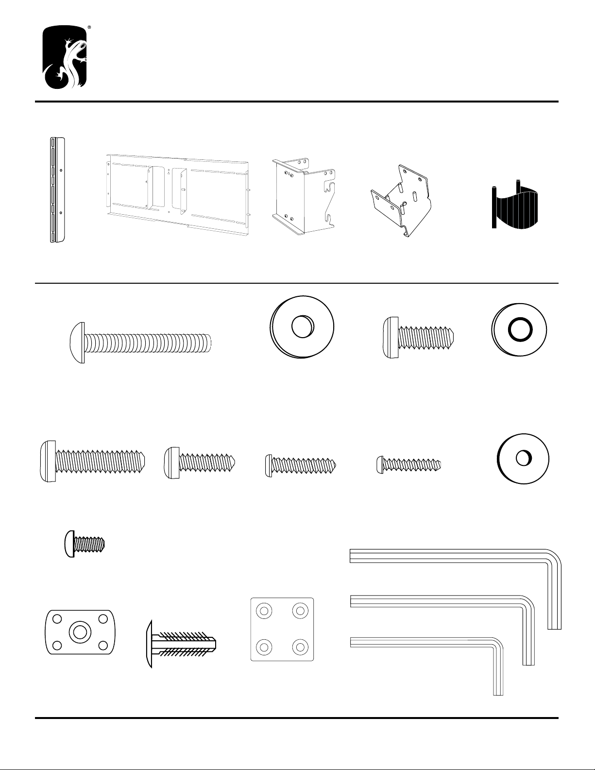
Parts
Synergy Twin Panel Mount - SN/PM
E (1x) 3” Square Extruded Post
A (2x) 301-400
Vertical Bracket
B (1x) 301-406
Interface Bracket
C (1x) 301-416
Post Bracket
D (1x) 301-422
Base Plate
F (5x) 301-600
Wire Manager
Synergy Twin Mount Hardware Bag - PHK-513
G (1x) 300-555
2” Button Head
Alternate Fasteners - Be sure to utilize the matching washers with the enclosed screws. (Use screws I, J and K with washer L
and
K (4x) 301-700
M8 x 30mm Phillips Head
L (4x) 301-710
M6 x 20mm Phillips Head
H (1x) 300-470
Metal Washer
M (4x) 301-715
M5 x 20mm Phillips Head
I (4x) 301-705
M8 x 20mm Phillips Head
N (4x) 301-720
M4 x 20mm Phillips Head
J (4x) 301-460
M8 Bonded Washer
O (4x) 300-515
1/4” Bonded Washer
Q (14x) 300-485
Button Head Screw
U (1x) 400-060 3/16” Hex Key
V (1x) 400-080 5/32” Hex Key
W (1x) 400-070 1/8” Hex Key
R (8x) 300-560
Flat Nut
Salamander Designs Ltd. www.salamanderdesigns.com 800-535-5659
© 2012 Salamander Designs Ltd. Doc No. 500-885 / v10.12 / 1 of 5
S (4x) 301-575
Plastic Fasteners
T (1x) 301-425
Post Cover
Page 2
BEFORE YOU BEGIN
BACK EDGE
• Carefully inspect the mount for shipping damage or missing parts. If any damage is apparent or you are missing parts contact
Salamander Designs at 800-535-5659.
• Read ALL assembly instructions before assembly. If you have any questions, please contact your installation contractor
or Salamander Designs.
• This TV mount is intended for use with Flat-Panel TV 50” or smaller.
• Total weight capacity of TV WITH optional speaker mount kits: Synergy Twin Cabinet Mount (SO/PM): 150 lbs.
• Use with products heavier than the maximum weight or larger than the size indicated may result in instability causing possible injury.
• Mounts must be attached as specified in assembly instructions. Improper installation can result in serious personal injury.
LIMITED WARRANTY- For five full years Salamander Designs Ltd. will repair or replace, at our option, any product defective
in materials or craftsmanship. Salamander Designs Ltd. will not be responsible for any damage to or destruction of other equipment
consequential to our equipment failure. Defective product must be given Return Authorization and is to be returned to the factory
prepaid, in the original carton and packing material. Any damage incurred in a shipment not in original packaging shall be the
responsibility of the owner. Warranty repairs will be returned prepaid, via UPS within the continental U.S.A. only.
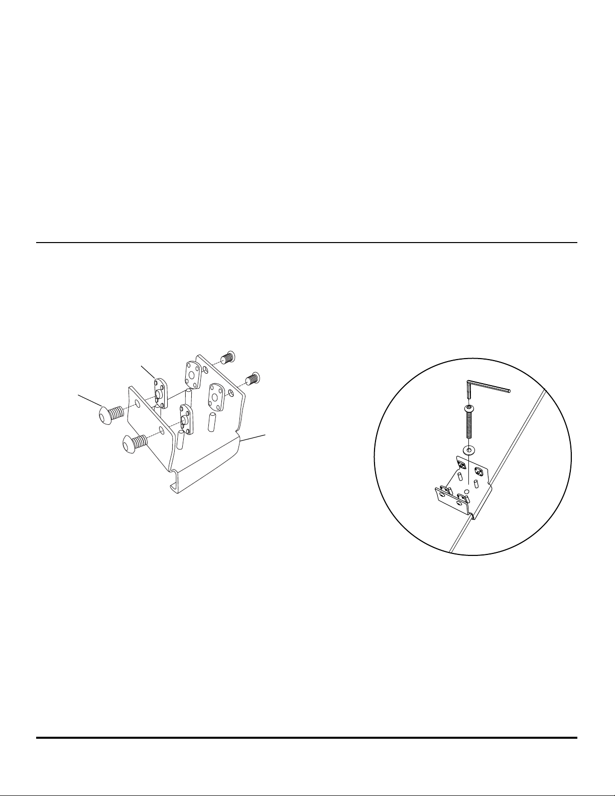
1. Install Base Plate
A. Loosely assemble 2 flat nuts (R) with 2 button
head screws (Q) through the base plate (D).
B. Secure the base plate (D) to rear center post with the 2” button
head screw (G) and washer (H).
Tighten firmly with hex key (U).
R
Q
D
NOTE:
If installing mount to an assembled twin unit, remove
the rear center connector bolt. Replace with base plate (D).
U
G
H
D
Salamander Designs Ltd. www.salamanderdesigns.com 800-535-5659
© 2012 Salamander Designs Ltd. Doc No. 500-885 / v10.12 / 2 of 5
Page 3

2. Install Post
A. Align thru holes in post (E)
over the pins in the base plate.
Guide the flat nuts (R) through
the front of the post.
If necessary, use rubber mallet or
other device to ensure the post fits
snugly against the top surface.
Tighten the screws (Q) with
hex key (V).
E
R
D
3. Mount Vertical Brackets to TV
Follow manufacturer’s recommendation for mounting (specified screw positions and fasteners).
Utilize the screws (I) and washers (J) provided* to secure the vertical brackets (A) to the TV. The vertical brackets (A) should
be centered on the television for best results.
*NOTE: Alternate fasteners provided for TV’s with recessed screw threads. Only use the longer screws (K) when the
standard screws and washers are not of sufficient length.
A
J
I
A
Center brackets vertically on TV.
A
Salamander Designs Ltd. www.salamanderdesigns.com 800-535-5659
© 2012 Salamander Designs Ltd. Doc No. 500-885 / v10.12 / 3 of 5
Page 4

4. Attach Interface Bracket to Vertical Brackets
You must install optional speakers mounts before continuing (FX200/LRK and FX200/CK) .
NOTE: Arrow indicates UP on interface bracket (B).
Center the interface bracket (B) horizontally on the TV. Mount the horizontal bracket (B) (with optional speaker mounts) to
the two vertical brackets (A), using the 4 button head mounting screws (Q) and secure in place with hex key (V).
Q
V
5. Assemble Post Bracket
A. Take the post bracket (C), and assemble 4
button head screws (Q) with the 4 flat nuts (R).
Thread the screws to the nuts enough to ensure the
nut does not fall off.
B
UP
Center Horizontally onto Vertical
B. Slide the post bracket (C) into the post (E) as shown
below, guiding the flat nuts (R) to ensure all parts slide freely.
Position the post bracket vertically along the post where
you wish the center of the television to rest.
Tighten screws (Q) with hex hey (V) to firmly set the bracket
C
onto the post.
Q
CAUTION:
R
E
R
Salamander Designs Ltd. www.salamanderdesigns.com 800-535-5659
© 2012 Salamander Designs Ltd. Doc No. 500-885 / v10.12 / 4 of 5
Page 5

CAUTION:
CAUTION:
6. Place TV onto Post Bracket
Pick-up the TV and guide the pins from the interface bracket (B) onto the post bracket (C) receptacles as shown in Diagram A
(TV may be positioned flat or tilted approximately 7 degrees). Secure the TV in place using the 2 button head screws (Q) with
the hex key (V) at both ends of the post bracket.
Diagram A
Tilt Flat
NOTE: Two people needed for this step.
Q
V
7.
Post Cap & Wire Managers
A. Using the 4 plastic fasteners (S) attach the post cap (T).
S
T
B. Attach the wire managers (F) by snapping
them into the backside of the post.
Squeeze to remove.
F
Salamander Designs Ltd. www.salamanderdesigns.com 800-535-5659
© 2012 Salamander Designs Ltd. Doc No. 500-885 / v10.12 / 5 of 5
 Loading...