

Page 1
SYNERGY TRIPLE PANEL MOUNT
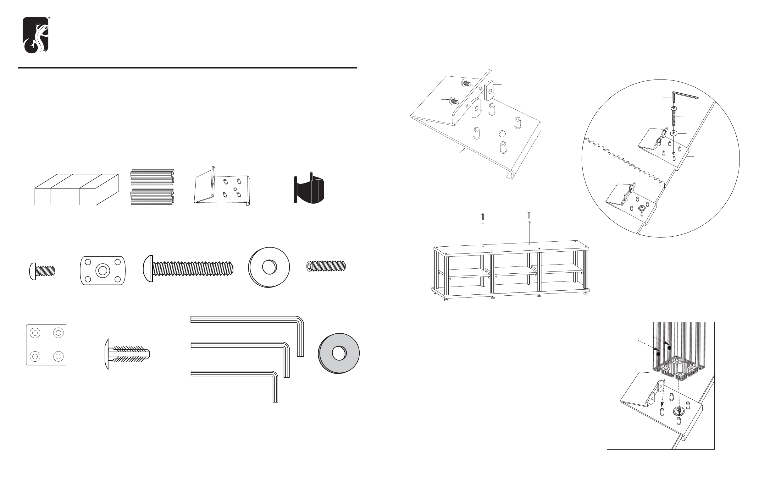
1. INSTALL BASE PLATES
SL /PM2
BEFORE YOU BEGIN
• This TV mount is intended for use with Flat-Panel TV 60” or smaller and a maximum weight of 175lbs.
• Use with products heavier than the maximum weight or larger than the size indicated may result in instability causing possible injury.
• Carefully inspect the mount for shipping damage or missing parts. If any damage is apparent or you are missing parts contact
Salamander Designs at 800-535-5659.
• Read ALL instructions before assembly. If you have any questions, please contact your installation contrator or Salamander Designs.
• Mounts must be attached as specified in assembly instructions. Improper installation can result in serious personal injury.
PARTS
FX 100/L
Fx 100/L Mount Kit
2 Extruded Posts
R (2x) 301-422 Base Plate
S (5x) 301-600
Wire Manage
A . Loosely assemble 2 flat nuts (G) with 2 button
head screws (F) through each base plate (R).
B. Secure the base plates (R) to the two rear center posts with
the 2” button head screws (K) and washers (L)
Tigh t en f ir m ly w ith h ex k e y (J ) .
G
F
N
K
L
R
R
NOTE:
If installing mount to an assembled triple unit, remove
the two rear center connector bolts. Replace with base plates (R).
r
BACK EDGE
SYNERGY TRIPLE MOUNT HARDWARE BAG -PHK-516
F (8x) 300-485
Button Head Screw
G (16x) 300-560
Flat Nut
K (2x) 300-555
2” Button Head
N (1x) 400-060 3/16” Hex Key
O (1x) 400-070 1/8” Hex Key
P (2x) 301-425
Post Cover
Q (8x) 301-575
Plastic Fasteners
S (1x) 400-080 5/32” Hex Key
L (2x) 300-470
Metal Washer
M (8x) 300-505
Cup Point Set Screw
R (4x) 300-468
Washer
Black
2. INSTALL POSTS
A . A lign thru holes in posts over the pins in the base plates.
Guide the flat nuts (G) through the front of the posts.
If necessary, use rubber mallet or other device to ensure the
posts fits snugly against the top surface.
Tighten the screws (F) w ith hex key (H).
Thru Holes
Page 2
B. A ssemble 8 flat nuts (G) with 8 set screws (M) and
drop into the left and right sides of each post.
G
C. Position the set screws (M) into the thru holes and tighten
through to the base plate pins. This will lock the posts to
the top of your Synergy cabinet.
Tighten firmly w ith hex key (O).
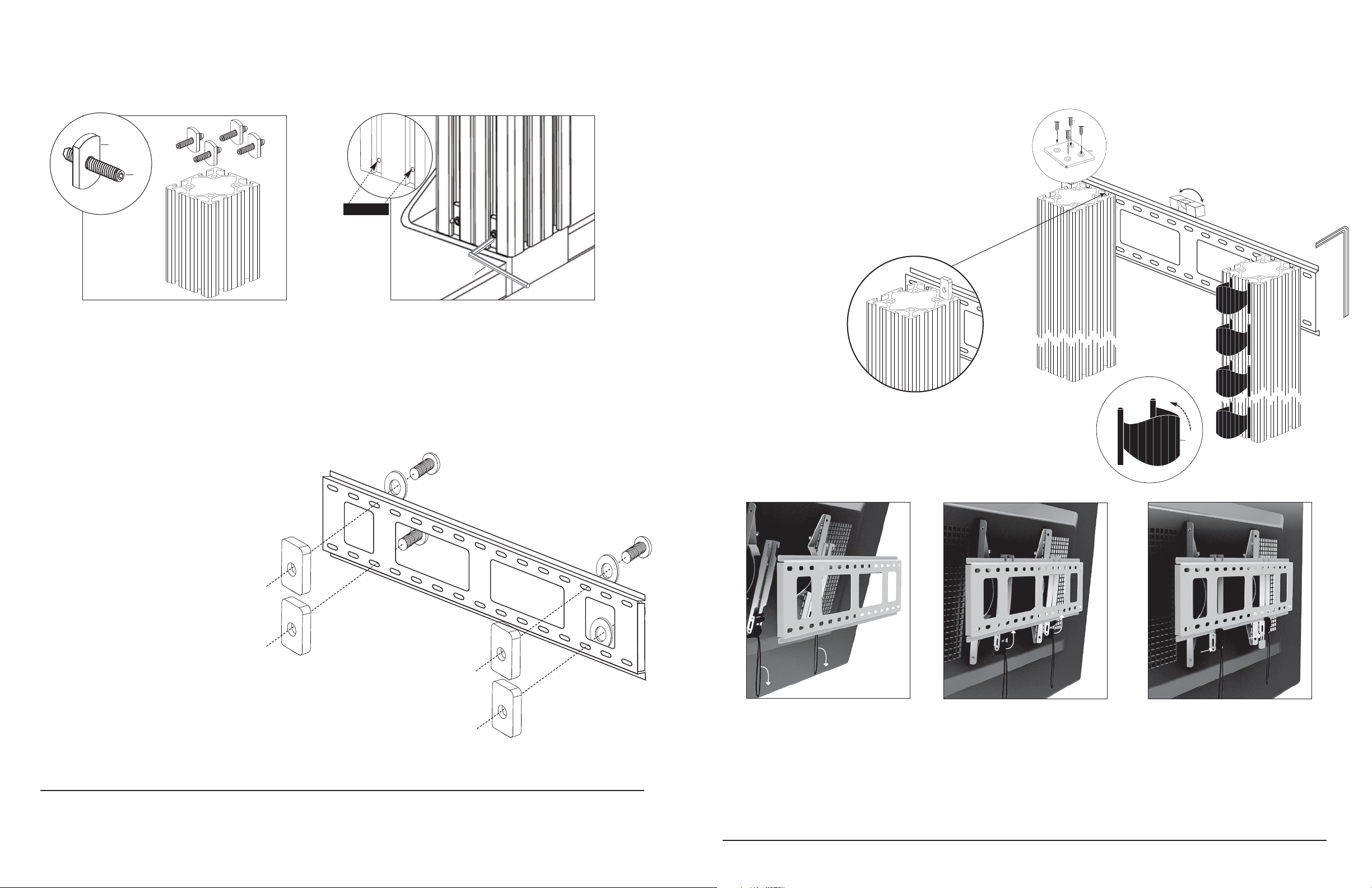
5. INSTALL POST BRACKET WIRE MANAGERS & CAPS
Q
Slide the post bracket into the posts as shown below,
guiding the flat nuts (G) to ensure all parts slide freely.
P
M
Thru Holes
3. ATTACH TV BRACKETS TO TV
Refer to Step 2 of the Flexo 100/L Manual.
4. ASSEMBLE POST BRACKET
Assemble 1 Button Head Screw with Washer
through the indicated slot (4 places) with flat nuts
loosely on each.
L
Position the post bracket vertically along the posts where
you wish the center of the television to rest.
Tighten button head screws (F) with hex key (H) to firmly
set the bracket onto the posts.
O
Squeeze to remove.
S
F
6. HANG TV
Thread the screws loosely to the nuts just enough
to ensure the nut does not fall off.
F
L
G
G
G
G
LIMITED WARRANTY- For five full years Salamander Designs Ltd. will repair or replace, at our option, any product defective in materials or craftsmanship. Salamander Designs Ltd. will not be responsible for any damage to or destruction of other equipment consequential to our equipment failure.
Defective product must be given Return Authorization and is to be returned to the factory prepaid, in the original carton and packing material. Any
damage incurred in a shipment not in original packaging shall be the responsibility of the owner. Warranty repairs will be returned prepaid, via
UPS within the continental U.S.A. only.
F
F
A
Pull on black cord to unlock Click
Fasteners and hook TV Brackets (II)
onto Wall Bracket (I) from top.
B
Center TV Brackets (II) on Wall Bracket (I)
and push black Click Fasteners up into
lock position.
Salamander Designs Ltd. w w w.salamanderdesigns.com 800-535-5659
© 2010 Salamander Designs Ltd. Doc No. 500-888/ v11.10
C
Install Pad Lock (IV).
 Loading...