

Page 1
SYNERGY MEDIA DRAWER - SA/MD
R
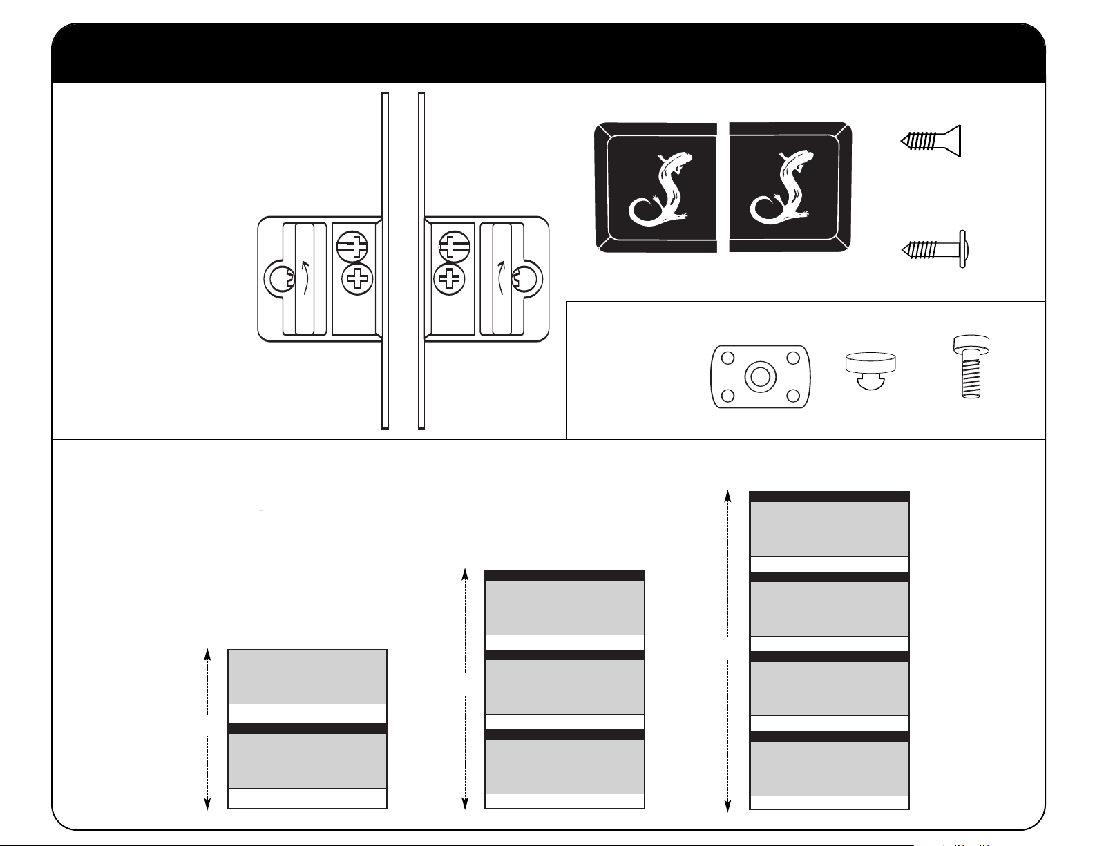
Parts
1 - Drawer Face (200-630)
2 - Metal Drawer Sides
1 - Bottom Panel (200-640)
1 - Drawer Back (200-650)
2 - Drawer Brackets (300-640)
6 - C/S Rivets
6 - Backup Washers
Drawer Spacer Tool
Use the Spacer Tool (included with base unit) for reference when
spacing drawers.
2 drawers on a SU20, 3 drawers on an SU30 or 4 drawers
on a SU40.
Refer to these measurements when installing
MAX DRAWERS=2
*No Adjustable Shelf on Top Drawer
1x
(300-670)
Fixing Hook (Left)
SU20
DRAWER 1
1x
(300-680)
Fixing Hook (Right)
MAX DRAWERS=3
27.75”
Shelf Bracket Bag
PHK-150
SU30
SHELF
DRAWER 1
GAP = 1.5”
SHELF
1x 1x
(300-690)
Cover Cap (Left)
(300-560) - Flat Nut
37.75”
(300-695)
Cover Cap (Right)
4x
SU40
MAX DRAWERS=4
SHELF
DRAWER 1
GAP = 1.625”
SHELF
GAP = 1.625”
SHELF
4x
(300-610)
Rubber Tab
5x
(300-110)
No. 6 Screw
11x
(300-115)
Black Screw
4x
(300-490)
Low Head Screw
17.75”
GAP = 1.5”
SHELF
GAP = 1.5”
GAP = 1.5”
SHELF
GAP = 1.5”
GAP = 1.625”
SHELF
GAP = 1.625”
Page 2
SALAMANDER DESIGNS
SALAMANDER DESIGNS
1
1 2 3 4 5 6 7 8 9
S20 / SVDO
REAR PANEL
4
1/2
"
6
8
www. sal am and erd esi gns .c om
EXTENDED
REAR PANEL
S30 / S40
REAR PANEL
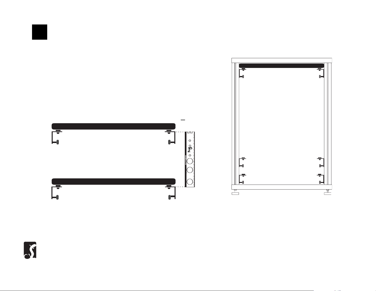
SPACER
TOOL
Installing Multiple Drawers
Note: Position the top of the Tool along the top of the first set of drawer
slides and set the next set of drawer slides to align along the bottom of
the Door. Tighten each set of drawer slides.
Adjustable Shelf
Note: The length of the Spacer Tool equals
the amount of space between drawers.
Limited Warranty
For five full years Salamander Designs Ltd will repair or replace, at our option, any product defective in materials or craftsmanship. Salamander Designs Ltd. will not be responsible for any damage to or destruction of other
equipment consequential to our equipment failure. Defective product must be given Return Authorization and is to be returned to the factory prepaid, in the original carton and packing material. Any damage incurred in a
shipment not in original packaging shall be the responsibility of the owner. Warranty repairs will be returned prepaid, via UPS within the continental U.S.A. only.
Salamander Designs Ltd. 800-535-5659 • www.SalamanderDesigns.com
Doc No. 500-380/v2 ©2002 Salamander Designs Ltd.
Page 3

2
Insert Drawer Slides
3
A. Place the low heads in the 2 holes of each
drawer slide and attach loosely.
Layout Sides
B. Insert the weld nuts into the channels
making sure that the rollers face the front of
the rack. Use the Spacer Tool provided and
the instructions on opposite side to help space
the drawer(s) as desired.
4
Place Bottom
C. Insert the Rubber Tabs into the 2 holes
on the shorter part of the bracket with the
flat side facing up.
Place the sides parallel to each other with the rollers on the top outer corners.
Place the bottom panel in between slides with the rounded edge facing
forward and make sure the pre-drilled holes are on the underside. Match the
bracket holes with the pilot holes and attach six black screws from bottom.
Page 4

R
5
Insert Back Panel
6
Add Fixing Hooks to Drawer Face
7
Drop the back panel into place, rounded edge up, matching pilot holes
with holes on the brackets and attach black screws from behind.
Attaching Panels
Slip the fixing hooks into the slots on the sides of the drawer. Apply downward
pressure to the drawer face until it stops. Then push the face in farther until it
audibly and physically locks into place.
Drawer Face
8
Adjustment screws on the fixing hook should face outside of the drawer box.
NOTE:
The two fixing hooks that attach to
the front panel are different. Each
Bracket is marked “R” or “L”.
REAR OF DRAWER FACE
Adjust Height and Add Trim Cover
NOTE: The upper screw on the sides of the drawer fixing hook is used to
adjust the height of the drawer if necessary. Loosen the lower screw and
adjust height of drawer face by turning the upper screw. Tighten lower
screw to lock in place Snap the two plastic covers with the Salamander
Logo over screw assembly.
 Loading...