

Page 1
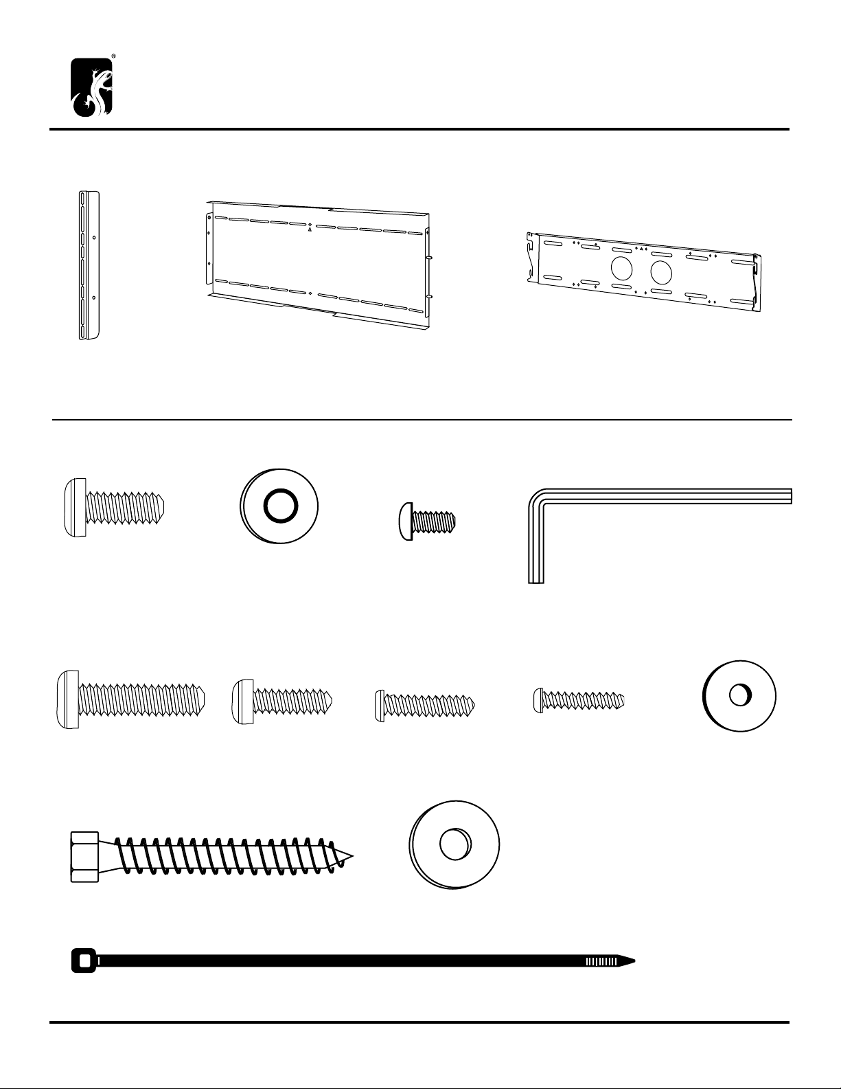
PARTS
FX200 Panel Mount Assembly Instructions
A (2x) 301-400
Vertical Bracket
B (1x) 301-920
Interface Bracket
C (1x) Tilt: 301-910 Fixed: 301-900
Wall Bracket
FX200 Mount Hardware Bag - PHK-700
D (4x) 301-705
M8 x 20mm Phillips Head
Alternate Fasteners - Be sure to utilize the matching washers with the enclosed screws. (Use screws E, I and J with washer F and
screws K and L with washer M.)
H (4x) 301-700
M8 x 30mm Phillips Head
E (4x) 301-460
M8 Bonded Washer
I (4x) 301-710
M6 x 20mm Phillips Head
F (10x) 300-485
Button Head Screw
J (4x) 301-715
M5 x 20mm Phillips Head
K (4x) 301-720
M4 x 20mm Phillips Head
G (1x) 400-080 5/32” Hex Key
L (4x) 300-515
1/4” Bonded Washer
M (4x) 301-730 Lag Bolt
(3x) 400-010 Cable Ties
Salamander Designs Ltd. www.salamanderdesigns.com 800-535-5659
©2005 Salamander Designs Ltd. Doc No. 501-400 / v10.09 / 1 of 5
N (4x) 300-470
Flat Metal Washer
O (4x) 300-560
Flat Nut
Page 2

BEFORE YOU BEGIN
• Carefully inspect the mount for shipping damage or missing parts. If any damage is apparent or you are
missing parts contact Salamander Designs at 800-535-5659.
• Read ALL assembly instructions before assembly. If you have any questions, please contact your installation
contractor or Salamander Designs.
• This TV mount is intended for use with Flat-Panel TV 63” or smaller. For larger Flat-Panel TV’s with mounting holes up to
38”W x 21.25”H use the FX200XLK expansion kit, sold separately.
• Total weight capacity of TV WITH optional speaker mount kits:
Salamander FX200 /L Wall Mounts: 220 lbs.
Synergy Triple & Quad Cabinet Mounts (SL/PM and SQ/PM): 180 lbs.
Synergy Twin Cabinet Mount (SN/PM): 150 lbs. Recommended 50” TV or smaller.
• Use with products heavier than the maximum weight or larger than the size indicated may result in instability
causing possible injury.
• Mounts must be attached as specified in assembly instructions. Improper installation can result in serious personal injury.
• The mount is designed to be installed using wall studs or supporting frame. Not for use on steel stud walls, old cinder
block walls, brick or concrete block. Installation to these type of walls will require other fasteners than provided.
• Use the mounting screws provided and DO NOT OVER TIGHTEN mounting screws.
TOOLS REQUIRED FOR INSTALLATION
• Phillips Screwdrivers, No. 2 Tip
• Drill and Bit Set
LIMITED WARRANTY- For five full years Salamander Designs Ltd. will repair or replace, at our option,
any product defective in materials or craftsmanship. Salamander Designs Ltd. will not be responsible for any damage
to or destruction of other equipment consequential to our equipment failure. Defective product must be given Return
Authorization and is to be returned to the factory prepaid, in the original carton and packing material. Any damage incurred in a shipment not in original packaging shall be the responsibility of the owner. Warranty repairs will be
returned prepaid, via UPS within the continental U.S.A. only.
Salamander Designs Ltd. www.salamanderdesigns.com 800-535-5659
©2005 Salamander Designs Ltd. Doc No. 501-400 / v10.09 2 of 5
Page 3

1. Mount Vertical Brackets to TV
Follow manufacturer’s recommendation for mounting (specified screw positions and fasteners).
Utilize the screws (D) and washers (E) provided
be centered on the television for best results.
Expansion Kit available (FX200/XLK) for TV’s with mounting holes up to 38”W x 21.25”H. FX200/XLK
brackets replace the standard vertical brackets (see Diagram 1).
*NOTE: Alternate fasteners
provided for TV’s with recessed
screw threads. Only use the
longer screws (H) when the
standard screws and washers
are not of sufficient length.
A
E
D
* to secure the vertical brackets (A) to the TV. The vertical brackets (A) should
A
Center brackets vertically on TV.
A
Diagram 1:
Expansion Brackets,
sold separately.
2. Attach Interface Bracket to Vertical Brackets
You must install optional speakers mounts before continuing (FX200/LRK and FX200/CK) .
NOTE: Arrow indicates UP on interface bracket (B).
Center the interface bracket (B) horizontally on the TV. Mount the horizontal bracket (B) (with optional speaker mounts) to
the two vertical brackets (A), using the 4 button head mounting screws (F) and secure in place with hex key (G).
F
G
UP
Center Horizontally onto Vertical
B
Salamander Designs Ltd. www.salamanderdesigns.com 800-535-5659
©2005 Salamander Designs Ltd. Doc No. 501-400 / v10.09 / 3 of 5
Page 4

3A. Installing Bracket Onto Wall
CAUTION:
Skip this step if you will be mounting your TV onto a Synergy cabinet. See Synergy Mounting Instructions.
WARNING!
Wall or mounting structure must support four times the combined load of all attached components and equipment.
1. Using a stud finder locate CENTERS of two adjacent
wood studs, typically 16” apart and mark with a
nail or pencil as shown in diagram A.
Marks must be horizontally level.
2. Pre-drill a 2.5” deep hole at the desired height in
each stud using a 3/16” drill bit. Use the wall
bracket to mark the location of the lower set of holes
in each stud. Drill a second set of 2.5” deep holes
using the 3/16” drill bit.
NOTE:
Center of wall
bracket (C) is the
same as center
of TV panel.
16” Apart
Diagram A
NOTE:
It is best to use a nail or awl to verify center of
stud location. The holes will be covered by the wall
bracket.
3. Attach the wall bracket (C) using the 4 lag bolts (M) and
4 metal washers (N). Make sure wall bracket is level to
secure vertical installation and then fully tighten lag bolts (M).
DO NOT OVER TIGHTEN to prevent splitting of stud.
UP
Wood
Stud
N
M
C
3B. Installing Bracket Onto Synergy Wall System
Salamander Designs Ltd. www.salamanderdesigns.com 800-535-5659
©2005 Salamander Designs Ltd. Doc No. 501-400 / v10.09 / 4 of 5
If installing the mount onto a Quad Wall, follow the assembly instructions for the PM/SQK (Wall
Adapter, Sold Separately) before proceeding.
1. Take the wall bracket (C), and assemble 4 button head screws (F) with the 4 flat nuts (O) through the outer set of holes on
each side of bracket as shown. Thread the screws to the nuts enough to ensure the flat nuts does not fall off.
F
C
O
Page 5

2. Slide the 4 flat nuts (O) down the front channel
of the 2 center posts of the Synergy Wall.
O
3. The wall mount may be placed anywhere along the rear posts.
Secure the button head screws (F) in place using the hex key (G).
F
G
4. Place TV onto Wall Bracket
Pick-up the TV and guide the pins from the interface bracket onto the wall bracket receptacles as shown in Diagram B
(TV may be positioned flat or tilted approximately 7 degrees). Secure the TV in place using the two button head screws (F)
with the hex key (G) at both ends of the wall bracket.
Diagram B
Tilt Flat
F
NOTE: Two people needed for this step.
G
Salamander Designs Ltd. www.salamanderdesigns.com 800-535-5659
©2005 Salamander Designs Ltd. Doc No. 501-400 / v10.09 / 5 of 5
 Loading...