


No.3498-35760-2
OPERATING & MAINTENANCE INSTRUCTIONS
RAMMER
Series
Be sure to operate, inspect, and maintain the products after you
have read this manual carefully to understand the contents.
RS45, RS65, RS75


Forward
Forward
This manual has been prepared as a guide to operate SAKAI RAMMER, RS45, RS65,
RS75.
It is hoped that the manual is useful for experienced operators to refresh the knowledge and
the experiences as well as for inexperienced operators.
You are requested to use this product after you have fully understood the contents of this
manual. Furthermore, keep this manual at a suitable place for your easy access.
Refer to a separate Engine Operation Manual for operation and maintenance of the engine.
If you lend or let other person to operate the machine, thoroughly explain how to operate
it and guide him to read this manual in advance before operation. In addition, if you transfer the product to someone, provide him with the Engine Operation Manual as well as this
instruction manual.
Please note that the purchased product may be somewhat different in the the contents of the
manual due to our constant efforts to improve its design.

Contents
Contents
When you order parts or get instructions for trouble correction
...........
1
Safety precautions
..................................................................................
2
1. Basic safety precautions
..................................................................
4
2. Sticking position of warning notice (Label)
....................................
7
3. Inspection before operation
.............................................................
9
4. Starting-up
.......................................................................................
13
5. Operation
.........................................................................................
16
6. Shutting down
..................................................................................
17
7. Inspection and Maintenance
............................................................
18
8. Fuel and Lubricant
...........................................................................
20
9. For a long-term storage
....................................................................
21
10. Overall View
....................................................................................
22

1
When you order parts or get instructions for trouble correction
When you order parts or get instructions for trouble cor rection
Be sure to inform us of the MODEL and its CHASSIS NUMBER when you are ordering
parts or getting instructions for trouble correction. The PRODUCT MODEL and BODY
NUMBER(Serial No.) are indicated on the body name plate.
The name plate is stuck on the left hand side of the body.
MODEL CHASSIS NUMBER
RS45 VRS4- 〇〇〇〇〇
RS65 VRS2- 〇〇〇〇〇
RS75 VRS3- 〇〇〇〇〇
MASS
MODEL CHASSIS NUMBER (Serial No.)

Safety precautions
2
Safety precautions
In order to use this product safely, correct operation and periodical maintenance are absolutely essential. Do not operate and/or carry out maintenance of the product until you read
the manual carefully to understand the safety precautions.
The operation and safety precautions illustrated in this manual are only limited for what it
is to be used as a rammer. If the product is to be used for works other than what the manual
covers, every safety consideration must be made on your responsibility.
In this manual, precautions. if they are failed to be observed, which may lead to an accident
resulting in injury or death, are marked as "
DANGER" or " WANING".
Precautions, if they are failed to be observed, which may lead to injury or to serious damage
to the machine, are marked as " CAUTION", and for precautions which may result in
damage to the machine or shortening its service life are marked as "IMPORTANT".
In addition, labels indicating precautions in carrying out safety operation and maintenance
service are stuck on the rammer as follows:
DANGER Indicates extremely high risk of an acci-
dent resulting in serious injury or death if
it is failed to be observed.
(This is marked in red.)
WANING Indicates a possibility to an accident
resulting inserious injury or death if it is
failed to be observed.
(This is marked in orange.)
CAUTION Indicates a possibility resulting in injury
or damage to the machine if it is failed to
be observed.
(This is marked in yellow.)

3
Safety precautions
Do not operate the machine until the
operator has understood the contents
by reading this manual carefully.
Wrong operation may invite an accident resulting in injury or death.
Safety operation of the machine is on
operator's responsibility.
In order to avoid an accident, you are requested to pay close attention to the safety other than
the precautions indicated in this manual and/or on the labels during machine operation, as
they could not cover all the precautions by foreseeing any possible danger.
WANING
☆ Cautions to be taken when making an alteration of the machine:
Making an alteration without our recommendation is a matter of question in terms of safety.
Contact our local sales agent or office in advance for alteration.
We will not bear any responsibility for injury or breakdown of machine resulted from alteration without approval from our side.
☆ Basic safety precautions to be taken in operating the machine are illustrated on the next
page on.

4
1. Basic safety precautions
1. Basic safety precautions
■ Read the instruction manual carefully.
● Understand functions of operation control equipment and
familiarize yourself with where it is and how to control it.
Also, have a proper understanding of how to operate and
meaning of each symbol.
■ Observe the rules in work site.
● Observe the established rules such as prohibitions in the work site, cautions, and work
procedures.
■ Wear clothes suitable for the work, and protective means.
● Wear clothes suitable for the work, safety shoes, and safety cap.
● Do not wear clothes which are likely to be caught in a projection of the machine, and/or
an ornament. Also, do not wear a clothe stained with oil as it may catch fire easily.
● Never forget to wear protective goggles and a mask when required in the work.
■ Handle with care when hot members are at high temperature.
● Take care not to be burned as the engine as a whole is very hot
during operation or immediately after it has been stopped.
● Do not allow your hand, body and clothe to be touched to the
muffler as it is very hot while the engine is running or immediately after it has been stopped.
● Take care, while the engine is still hot, not to be burned from oil
spray when draining or filling oil.
Be sure to observe the safety precautions to secure safety.
Failure to observe the precautions will
invite accidents or machine troubles.
WANING

5
1. Basic safety precautions
■ Pay attention to fire.
● Bringing a open flame close to fuel and oil may invite a fire.
In particular, fuel can catch fire very easily and it is dangerous.
● Do not bring a fire such as of cigarette or of match close to the
flammable materials.
● Supply fuel with the engine stopped after no fire has been confirmed around the rammer.
● Tighten the caps such as for fuel and for oil securely.
■ Pay attention to ventilation.
● Exhaust gas is harmful for your health. If the engine has to be
run in a room or in a poorly ventilated area, ventilate the area by
opening windows and/or entrances.
■ Check the machine body before operation.
● Check to see if each part of the machine functions properly at a safe place. If it is found
anything wrong, be sure to take corrective measures to start operating the machine.
● Check the machine for unusual noise, unnatural vibration, heat and smell. If it is found
something wrong, stop the machine at a safe place immediately and check and locate the
cause to repair it.
■ Be careful not to be caught in the machine.
● Do not stand close to the machine while operating the machine
because your hand, body, or clothe is likely to be caught in the
rotating members which may result in an injury.
Be careful not to be caught in the machine. Be sure to stop the
engine before performing inspections and maintenance for rotating members and their vicinities.
6
1. Basic safety precautions
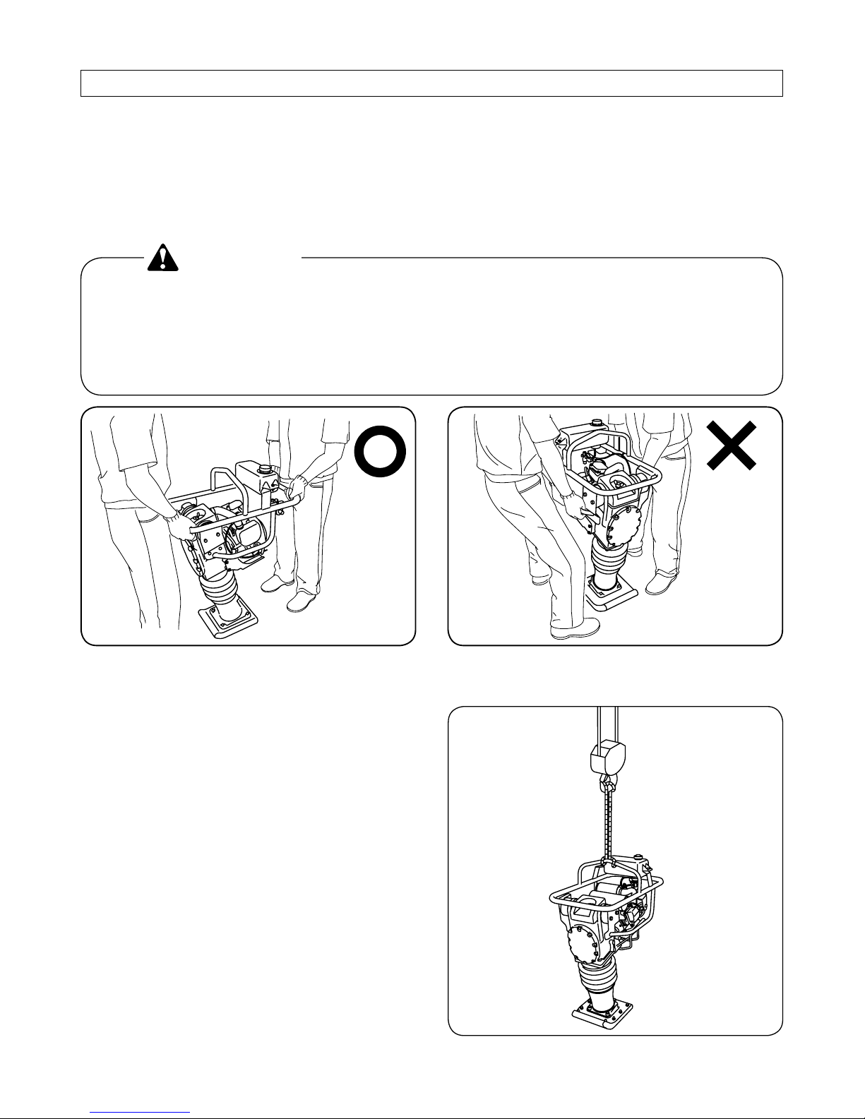
■ Cautions to be taken when loading and unloading using a crane.
● Surely bind the guard with a wire rope
as shown in the figure on the right.
■ Cautions to be taken when loading and unloading the machine.
● Load and unload the machine in/from a transporting vehicle with two persons in order to
avoid an accidental drop of the machine.
● Drain fuel from the fuel tank, the carburetor, and the fuel strainer before transporting it
on a long distance or on a rough road.
When lifting up the machine by holding the handle, hold
the handle at its front and rear part to prevent your finger
and/or hand from being caught between the handle and the
machine body.
•
DANGER
7
2. Sticking Position of Warning Notice(Label)
①②③
2. Sticking Position of Warning Notice (Label)
For safety's sake, warning notice (label) is sticked to below mentioned position of our products.
Keep the label clean and free of breakage. If it is broken or missed, replace it with a new one.
When ordering labels, be sure to mention the relative part number printed at the bottom right
corner of it.

8
2. Sticking Position of Warning Notice(Label)
① 3998-36001-0
② 3998-06140-0
③ 3998-16491-2
• Read the operator's manual thoroughly before operating
the machine.
• Incorrect operation can cause severe injury or death.
• It is your responsibility to operate the machine safely.
3998-16491-2
WARNING
Detail of Warning Notice (Label)

9
3. Inspection before operation
3.1. Engine
Refer to a separate Engine Operation Manual for the engine.
3. Inspection before operation
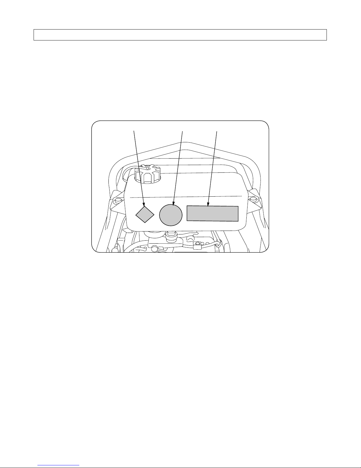
Oil gauge
Fill port
Drain plug
Maximum oil level
Minimum oil level
(Refill is required)
① Remove the oil gauge and wipe off oil
stuck on the gauge with a rag.
② Push the oil gauge against the oil fill port
without screwing it in to check oil level.
③ Refill oil until it comes to the upper limit
mark when the level is insufficient.
Be sure to check and refill oil with the engine held level.
Check the oil level again at approx. 3 minutes after it has been refilled.
Do not supply oil more than the specified since over-supply of oil may
result in blowing out of oil and poor output of the engine.
Shortage of oil may cause seizure of the engine.
If an oil other than the specified is used, service life of engine is likely to
be shortened.
•
•
•
•
IMPORTANT
Screw in the oil gauge securely after oil level has been
checked and refilled .
•
CAUTION
3.2. Checking oil in the engine chamber

10
3. Inspection before operation
Be sure to check and refill oil with the rammer shoe held level.
Run the engine for a while after oil has refilled then check the oil level
again at approx. 3 to 5 minutes after engine has been stopped. If oil has
been filled sore than the specified, malfunction results. Be sure to wipe it
off when over-filled.
If an oil other than the specified is used, service life of engine is likely to
be shortened.
•
•
•
IMPORTANT
Remove the fill plug located in the lower
cylinder case with the rammer shoe held
level and check that the oil is filled up to the
mouth of the port.
If it is found insufficient, supply oil to the
extent that it comes full to mouth of the
port.
Drain plug
3.3. Checking oil in the rammer cylinder
11
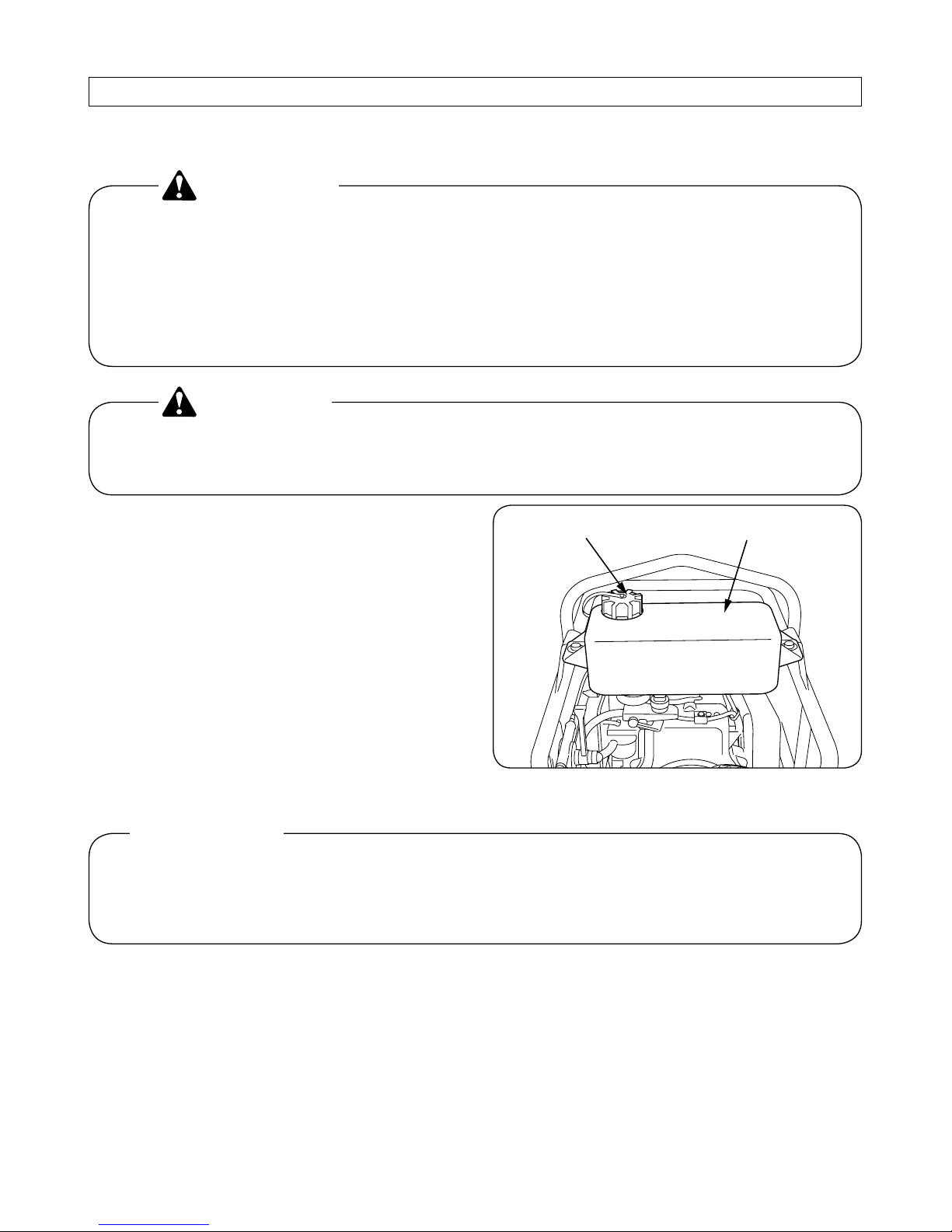
3.4. Checking fuel
3. Inspection before operation
Remove the cap on the fuel tank to check
remaining oil visually. Refill fuel if it is
found insufficient.
Fuel to be employed:
Regular gasoline for automobile
Wipe off fuel thoroughly when it has been spilled out.
Be sure to stop the engine when filling fuel.
Tighten the cap on the fuel tank securely after fuel has been
filled up.
Be sure to check if it is the right fuel before refilling fuel.
•
•
•
•
WARNING
In order to prevent fuel from being blocked. be sure to fill up
fuel through a filter.
•
CAUTION
Since shortage of fuel can cause irregular tamping motion due to uneven
fuel supply to the engine by vertical (vibrating) motion of the machine,
refill fuel a little earlier.
•
IMPORTANT
Fuel tankCap

12
3.5. Checking bolts and nuts for their tightness
Re-tighten bolts and nuts in each section after each operation and once a week.
Bolts and nuts are likely to become loose due to vibration of the machine body.
If it is operated with the bolts and/or nuts losened, malfunction and damage to the machine
may result.
In particular, be sure to check bolts and nuts securing tamping shoe before starting operation.
Since crankcase and its related members are made of aluminum, be careful not to over-tighten them.
•
CAUTION
3.6. Handle height adjustment
Handle height can be adjusted in two(2)
steps to meet the operator's height.
It can easily be adjusted by relocating handle counting bolts.
3. Inspection before operation
Although there are three (3) holes in the handle, do not use
the uppermost hole.
•
CAUTION

13
4. Starting-up
4. Starting-up
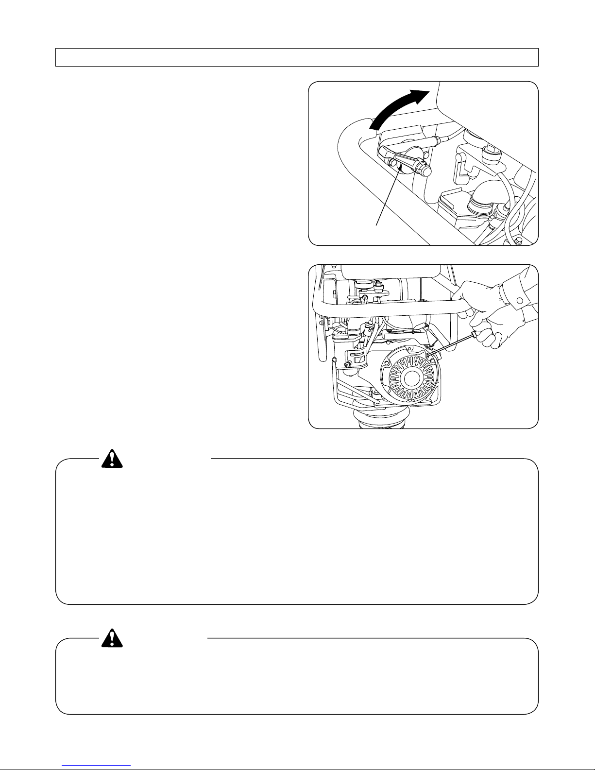
(1) Turn “ON” the engine switch serving
also as fuel cock.
ON
Fuel cock
(2) Close the choke lever in the carburetor.
RS45, RS65
Choke lever
Closed
RS75
Choke lever
Closed
Position the lever to a to a halfway between Closed and Fully open when
temperature is wars or the engine is still hot. Likewise, position the lever
to Closed when temperature is low.
•
IMPORTANT
14
4. Starting-up
(3) Turn the throttle lever to Fully Closed
position.
(4) Pull the starting knob forcibly.
Closed
Throttle lever
Do not pull out the rope up to its extreme. And when returning the rope, return it slowly as an abrupt release of the rope
will cause damage to the cover with a shock.
•
CAUTION
Start the engine after looking around to confirm the safety of
its surroundings .
Hold the handle securely with your left hand to fix the
machine body and pull the starter knob forcibly with your
right hand to start the engine.
Pull up the starter knob so that your hand will not hit the
handle.
•
•
•
WARNING

15
4. Starting-up
(5) Shift the choke lever to Fully open position after the engine has been started.
Warm-up the engine at an idling speed for approx. 5 minutes
after the engine has been started.
If the engine fails to start, check the spark plug and the fuel
system for blockage.
•
•
CAUTION

16
5. Operation
5. Operation
(1) Shift the throttle lever to Fully Open
position after the warm-up operation has
been completed.
Rammer starts ramming and moving forward.
Throttle lever
Open
During operation, do not lift up the machine by holding the
handle.
•
DANGER
Do not operate the engine with an intermediate speed as the
centrifugal clutch repeats ON and OFF in this speed which
may result in seizure of the engine.
Shift the throttle lever swiftly to Fully Open position.
If throttle lever is shifted slowly, it will cause irregular
machine motion and say damage clutch, springs, and tamping shoe.
Do not operate the rammer for driving a pile or on a solid
ground exceeding capacity of the machine such as surface
paved with asphalt, concrete, cobblestone, and solid rock.
Otherwise, this may cause damage to the machine as too
much stress is applied to the machine body.
Do not get your hands off the handle while operating.
When operating the rammer on a ground surface with a large
roughness and a large level difference, or on a steep slope,
take care that you will not be injured in your wrist due to
overturn or slip of the machine body.
In addition, this may cause earlier damage to the machine as
an excessive stress is also applied to the machine body.
Be sure to stop the engine before leaving the rammer unattended.
•
•
•
•
•
•
CAUTION

17
6. Shutting down
6. Shutting down
(1) Return speed control lever to the lowest
speed position and allow the engine to
run for 1 to 2 minutes for cooling.
Return the throttle lever swiftly as in the start-up operation.
Do not stop engine immediately after high-speed operation.
otherwise oil deteriorates or motion members are stuck fast
since the engine temperature rises suddenly.
•
•
CAUTION
(2) Turn “OFF” the engine switch serving
also as fuel cock and push it up for more
than 3 seconds to stop the engine.
Closed
Throttle lever
Fuel cock
OFF

18
7. Inspection and Maintenance
7. Inspection and Maintenance
7.1. Engine
Refer to a separate Engine Operation Manual for the engine.
7.2. Rammer body
Wipe off dust. dirt, and oil stuck on the body and inspect it for anything unusual.
Also, check bolts and nuts for tightness.
7.3. Spark plug
Remove the spark plug to clean off carbon deposit on the plug every 50 hours of
operation. Adjust electrode gap to between
0.6mm and 0.7mm.
Spark plugs to be employed:
RS65 CR5HSB (NGK)
7.4. Air cleaner
Remove the air-cleaner element (only the
part made of urethane) and clean it with
wash oil (kerosene) every 50 hours of operation.
After cleaning, dip it in blended oil (mixture
in the ratio of 1 for engine oil to 3 for kerosene) and squeeze it hard for reassembling.
RS75 BP4ES (NGK)
RS45,RS65
RS45 CR4HSB (NGK)

19
7. Inspection and Maintenance
7.5. Rammer cylinder
Change oil after initial 50 hours of operation
for the first time, and every 200 hours of
operation thereafter. Wipe off the oil stuck
on the rammer after oil has been changed.
How to change oil:
Remove the drain plug and tilt the rammer
to discharge oil, then fill in the new oil.
Position the tamping shoe to be level to supply oil until it will overflow out of the drain
plug.
Quantity specified
RS45 : 500cc
RS65 : 800cc
RS75 : 900cc
Drain plug
7.6. Checking bolts in each section for their tightness
Check the mounting bolts for tightness. In particular, pay special attention around to the bolts
securing engine, crankcase, tamping shoe, and control handle.
RS45,RS65
RS75

20
8. Fuel and Lubricant
8. Fuel and Lubricant
8.1. Fuel
Fuel to be employed : Regular gasoline for automobile
Fuel tank capacity : 2.2 liters
8.2. Engine oil/Vibrator oil
Season Ambient temperature Viscosity rating
Summer
Spring/Autumn
Winter
All-year-round
25℃ and above
25℃〜 10℃
10℃〜 -10℃
Regardless of temperature
SAE#30
SAE#30 or #20
SAE#20
SAE 10W-30

21
9. For a long-term storage
9. For a long-term storage
(1) Drain fuel from the fuel tank and the carburetor completely and close the fuel cock.
(2) Pull the starter knob slowly until resistance is felt and leave it in this condition.
(3) Check the engine and the vibrator for oil leakage.
(4) Wipe off oil stains, if any, on the rubber dampers.
(5) Check bolts and nuts for tightness and re-tighten them as necessary.
(6) Put the cover over the rammer and store it in a dust-free, dry area.
(7) Remove the ignition plug to inject approximately 5cc of engine oil into the cylinder.
Then fit the plug and tighten it after the starter knob has been pulled up 2 or 3 times
repeatedly.

22
10. Overall View(RS45)
10. Overall View
RS45
370
230
340
700
870
965
Model RS45
Physical
Machine Weight *1 49kg
Total Length 700mm
Total Width 370mm
Total Height 965mm
Size of Tamping Plate 340mm(L) × 230mm(w)
Performance
Traveling stroke 40~60mm
Frequency 10.8~11.5Hz (650~690vpm)
Traveling Speed 8~12m/min
Engine
Manufacturer's Model HONDA model GX100KR
Maximum Output *2 2.2kW (3.0ps)/3600min
− 1
(rpm)
Fuel Gasoline
Starting System Recoil starter
*1. Indicating condition of the weight:
The weight to be indicated includes half the weight of fuel of the tank capacity and does not
include the weight of water for sprinkling use.
*2. Engine output indication:
This indicates maximum output at the operating speed.
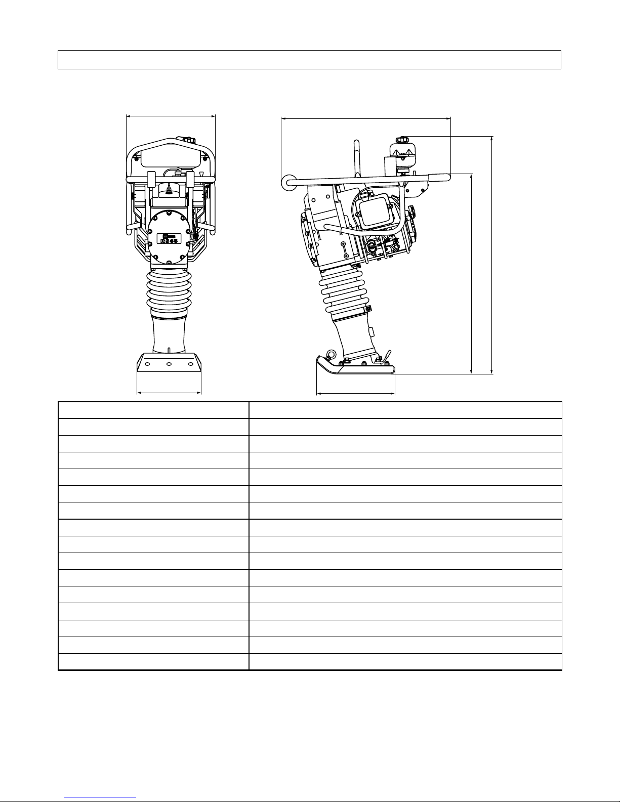
23
10. Overall View(RS65)
RS65
390
280
340
740
875
1040
Model RS65
Physical
Machine Weight *1 71kg
Total Length 740mm
Total Width 390mm
Total Height 1040mm
Size of Tamping Plate 340mm(L) × 280mm(w)
Performance
Traveling stroke 50~70mm
Frequency 10.7~11.3Hz (640~680vpm)
Traveling Speed 16~20m/min
Engine
Manufacturer's Model HONDA model GX100KR
Maximum Output *2 2.2kW (3.0ps)/3600min
− 1
(rpm)
Fuel Gasoline
Starting System Recoil starter
*1. Indicating condition of the weight:
The weight to be indicated includes half the weight of fuel of the tank capacity and does not
include the weight of water for sprinkling use.
*2. Engine output indication:
This indicates maximum output at the operating speed.

24
RS75
10. Overall View(RS75)
415
280
340
795
875
1040
Model RS75
Physical
Machine Weight *1 80kg
Total Length 795mm
Total Width 415mm
Total Height 1040mm
Size of Tamping Plate 340mm(L) × 280mm(w)
Performance
Traveling stroke 50~70mm
Frequency 10.3~12.0Hz (680~720vpm)
Traveling Speed 17~21m/min
Engine
Manufacturer's Model HONDA model GX120K1
Maximum Output *2 2.8kW (3.7ps)/3600min
− 1
(rpm)
Fuel Gasoline
Starting System Recoil starter
*1. Indicating condition of the weight:
The weight to be indicated includes half the weight of fuel of the tank capacity and does not
include the weight of water for sprinkling use.
*2. Engine output indication:
This indicates maximum output at the operating speed.


2009.11.200 ② C.D
SAKAI HEAVY INDUSTRIES, LED.
Head office: 1-4-8, Shiba-Daimon, Minato-ku
Tokyo, Japan
Cable address: "SKWSAKAI" TOKYO
Telex: 242-3525 SKWMONJ
Telphone: Tokyo(03)3431-9971
November-2009
MODEL RS45, RS65, RS75


OPERATING & MAINTENANCE INSTRUCTIONS
 Loading...