


VM1000 Series
VM1000 AC Drive
User Manual
资料代码:
‐0‐
Version Code :VM1000-E2016-04-1MB

VM1000 Series
Preface
Thank you for choosing SAJ VM1000 AC drive.
This user manual provides you with technical specification, installation instruction
and detailed function parameters of VM 1000.Before installation, operation,
maintenance or inspection, please read this manual carefully.
Special warning: Please be sure to read and understand the warnings and precautions
in this manual before using VM 1000 and make sure the certificate of relative
electrical engineers is line with the provisions of the labor supervision
department, and the electrics and environment conditions is in conformity with the
country’s standard.
Make sure the wiring is correct before it is power-on; before normally operating and
using this product, make sure the motor rotation meets the requirements by
debugging it.
When installing, using or maintaining the product, if it needs a consultation for
product functions, performance, other technical issues as well as safety precautions,
please contact our customer service center according to the hotline in the manual.
China service hotline: 400-159-0088
‐1‐

VM1000 Series
Content
Preface .............................................................................................. - 1 -
Precautions ...................................................................................... - 4 -
Signs, Abbreviation and Brandmark statement ........................... - 8 -
Chapter 1 Product Information ..................................................... - 9 -
1.1 Production Introduction ................................................................................. - 9 -
1.2 Technical Specification Table ...................................................................... - 10 -
1.3 Product nameplate........................................................................................ - 13 -
1.4 Model Description ....................................................................................... - 14 -
1.5 Dimension of AC Drive ............................................................................... - 14 -
1.6 Dimension of Keyboard ............................................................................... - 17 -
1.7 Specification of Selecting Products ............................................................. - 18 -
1.8 Maintenance ................................................................................................. - 19 -
Chapter 2 Installation ................................................................... - 22 -
2.1 Mechanical Installation ................................................................................ - 22 -
2.2 Electrical wiring ........................................................................................... - 28 -
2.3 Electro Magnetic Compatibility ................................................................... - 43 -
Chapter 3 Panel Display and Operation ................................... - 46 -
3.1 Introduction of Operation&Display Interface .............................................. - 46 -
3.2 Function Code Viewing, Modification Instruction ...................................... - 49 -
3.3 Viewing Methods of Status Parameters ....................................................... - 50 -
3.4 Password Setting ........................................................................................ - 50 -
Chapter 4 Quick Debugging Guide ............................................. - 51 -
4.1 Preparation and Examination Before Commissioning Operation ................ - 51 -
4.2 Panel Operation ............................................................................................ - 53 -
4.3 Start/Stop control of terminal forward rotation ........................................... - 56 -
4.4 Common Control Guideline ......................................................................... - 58 -
4.5 Auto-tuning of Motor Parameters ................................................................ - 62 -
4.6 Faults Query and Reset step ......................................................................... - 64 -
4.7 Parameters Restore as Factory Value ........................................................... - 65 -
‐2‐

Chapter 5 Function Code Datasheet ......................................... - 66 -
Chapter 6 VM1000 Communication Application ..................... - 112 -
6.1 The Content of Protocol ............................................................................. - 112 -
6.2 Application ................................................................................................. - 112 -
6.3 Bus Structure .............................................................................................. - 112 -
6.4 Protocol Instruction .................................................................................... - 113 -
6.5 Communication Frame Description ........................................................... - 113 -
6.6 Register Address ........................................................................................ - 118 -
Chapter 7 Faults and Solutions ............................................... - 126 -
7.1 Fault Code Table ........................................................................................ - 126 -
7.2 Troubleshooting and Solution .................................................................... - 138 -
Appendix A -Selection of External Electrical Components ..... - 140 -
A.1 VM1000 External Electrical Connection Diagram ................................... - 140 -
A.2 Selection Guide of Braking Components ................................................. - 143 -
A.3 Selection of Air Switch,Contactor or Cable .............................................. - 145 -
Appendix B-Manual Revision Record ....................................... - 146 -
VM1000 Series
‐3‐

VM1000 Series
Precautions
The Definition of Manual Warning Signs
In this manual, there are three kinds of warning signs that is respectively
corresponding to three kinds of precautions; once violated, it will probably cause
person injury to different degree.
DANGER: it indicates that it will probably cause death or severe physical
injuries if violate the correct instruction.
WARNING: it indicates that it could cause personal moderate injuries, minor
injuries or damage to the equipment if violates the correct instructions..
NOTE: it indicates that it would cause error or using equipment insecurely if
violates the correct instruction.
The Definition of Product Warning Signs
The product warning signs are right under the case cover.
It indicates that there is high voltage in the product
+10 minutes time delay, which indicates that it needs to wait for capacitor
discharging after power off
Before Installation
Before opening, please confirm that:(1) model and rated values on the nameplates
is same as the goods you order; products, certification accessories, user manual and
warranty card are complete and have not been damaged;(2) Whether the products
are damaged or destroyed with water etc.; If there is damages,losses or other
abnormal phenomenon,please contact our company or your suppliers to solve
problems
‐4‐

VM1000 Series
Warning
◎Do not install or operate the VFD if it is damaged or has missing parts. Otherwise it may
result in equipment damage or physical injuries.
Installation
Warning
◎Please hold the bottom of VFD when installing or moving it. In case that the VFD is
broken or damaged; only holding the shell is not allowed.
◎Keep the VFD away from heat, inflammable and explosive goods; Install VFD on the
metal or other nonflammable objects.
◎If the VFD is mounted in an electric cabinet or other enclosed objects, fans or other cooling
device should be installed inside the cabinet; Setting ventilation opening to ensure ambient
temperature is below 40℃. Otherwise it may be damaged because of high temperature.
Danger
◎Wiring must be completed by qualified electrical engineers. Otherwise it can cause an
electrical shock or VFD damage.
◎Before wiring, make sure the power supply is de-energized. Otherwise it will cause an
electrical shock or a fire.
◎Make sure the ground terminal is grounded safely and correctly. Otherwise there will
be a risk of electrical shock on the shell of VFD.
◎Do not touch the main circuit terminal, and the main circuit terminals of the VFD are not
allowed to contact the shell. Otherwise it may cause an electrical shock.
◎Braking resistor of the connection terminal is (+)and PB. Do not connect the other terminals;
Otherwise it may cause a fire.
‐5‐

VM1000 Series
Wiring
Warning
◎Before connecting, make sure the voltage rating and phase number of VFD is conformed
to the input power voltage, phase number; Otherwise it may cause a fire or physical injuries.
◎Never connect the AC input power supply to the output terminals V, U, W of VFD;
Otherwise it will cause damage to the VFD and you are not guaranteed to enjoy the warranty
services.
◎Never conduct a pressure test on VFD;Otherwise it will cause damage to the VFD.
◎The main circuit wiring of the VFD and the control loop wiring should be separated or
vertical crossed, otherwise the control signal will be interfered.
◎The cable connected to the main circuit terminals should be use lugs with isolated casing.
◎If the length of cable between the VFD and the motor is over 50 meters, an output reactor
is recommended so as to protect the VFD and motor.
Operation
Danger
◎Turn on the input AC power after the wiring of VFD is completed and the front cover is
installed. Do not dismantle the front cover when operating; otherwise it will lead to an
electric shock.
◎When VFD is set with the function of fault automatic reset or auto-restart after power
failure, protection measures for equipment system should be taken in advance. Otherwise it
will cause physical injuries.
◎The key “RUN/STOP” may be lose efficacy because some function had been set, a
separate emergency power switch can be installed in the VFD control system; Otherwise it
may cause damage or physical injuries.
◎Though the VFD terminal is in stop state, the terminal is electrified after power on. Do not
touch; otherwise there will be a risk of electric shock.
Warning
◎Do not use the breaker to control the stop/start of AC drive, or it may damage to the AC
drive.
◎Because the acceleration time is short when AC drive makes motor operates from low to
high speed, make sure the motor and mechanical equipment is within the permitted range
‐6‐

before operation,or it will damage the equipment.
◎The temperature of heat sink and braking resistor is high. Please do not touch. Otherwise,
it may cause burns.
◎When leaving factory, the preset parameters of AC drive have met most of the
operational requirements of equipment. If not necessary, do not arbitrarily change the
parameters. Even some devices have some special requirements; you can only modify the
necessary parameters. Otherwise, arbitrary modification may damage the equipment.
VM1000 Series
Maintenance and Inspection
Danger
◎When power on, do not touch the connection terminals. Otherwise it may cause an
electrical shock.
◎Only qualified electrical engineering personnel can maintain, replace and inspect the SPD.
◎Wait at least 10 minutes after the power failure, or make sure that is no residual voltage
before carry out maintenance and inspection, otherwise it may cause damage.
Note
◎PCB board has CMOS integrated circuit, do not touch, otherwise the static electricity may
damage PCB board.
Others
Danger
◎It is strictly forbidden to transform the VFD, otherwise it may cause casualties. After
arbitrarily changing VFD, will no longer enjoy the warranty service.
‐7‐

VM1000 Series
Signs, Abbreviation and Brandmark statement
■ Signs
Protective Earthing: PE
Signal Ground: GND
Shield: SHIELD
■ Name Abbreviation
1. In this user manual, VM1000 AC drive has another name or abbreviation:
Variable frequency drive, VM1000, inverter, speed controller, VFD product and
product.
2. VFD parameter is as follows:function parameters, function code, parameters
code
3. SAJ, Sanjing Electric、SAJ Electric are all the standard abbreviation of
Guangzhou Sanjing Electric Co. Ltd
4. Common Technical Terms,Similar or Equal Name:
Voltage frequency ratio control mode: VF control
Open-loop vector control mode: SVC control
Three-phase induction motor: asynchronous motor, squirrel-cage asynchronous
motor
■ Trademark
1. Modbus○R is the trademark of Schneider Electric
2. SAJ○R is the trademark of Guangzhou Sanjing Electric Co. Ltd
3. Other trademark that may occur or product names belong to respective owners
‐8‐

VM1000 Series
Chapter 1 Product Information
1.1 Production Introduction
The Usage of VM1000 AC drive
VM1000 AC drive is the new generation product with high performance and multi
usages, which usually apply in the regular three-phase induction motor for speed
control. Power range is 11~110kW;It can select V/F control mode or SVC control
mode.
Key Design Points
Design Points Instruction
1.Product adopts: large capacity power module,high accuracy detection
hardware and brandnew control platform
Control
performance and
function
2.Function upgrade: mainly includes torque control,S curve,given
frequency,vector control, V/F separation, Two groups of PID
parameters,input、output and auxiliary function,faults protection and
user-defined protection action
3. Meanwhile,it maintain the compatibility for previous products
Input/Output and
communication
interface
G/P load types
Structure design
Support 5 common inputs, 1 high-speed pulse input, 1 high-speed
pulse output( also work as open collector output DO), 2 relay output, 2
analogue output, 2 analogue input, 1 RS485 communication interface
Whole series support heavy load(G) and normal load(P) rating
characteristics.
G load type: typical constant torque load, such as conveyor, lift, crane,
etc.
P load type: typical variable torque load, such as pump and fan.
Structure optimization, dimension decrease, good heat dissipation,
industrial protection, simple case
‐9‐

Wiring installation
New keyboard
design
1. Main circuit adopt increased superior terminal array,large power
type and independent terminal,and equipped with dual GND ports.
2. Control terminal is vertical arranged on the left of the control board
and print with PCB logo.
1. Adopt potentionmeter of electrical impulse,standard keyboard
adopts 5 bits digital tube to display and match LED lights;
2. Common keyboard supports short distance installation externally,
and adopts LCD keyboard to realize long-distance external leading by
cables
VM1000 Series
Faults detection
EMC Level
Faults type and strategy are more refined, user can define faults
protection action
standard product satisfy IEC61800-3 C3 requirements
external filter satisfy IEC61800-3 C2 requirements
Table 1-1 Product Key Design
1.2 Technical Specification Table
Item Specification
High frequency V/F control:0 ~ 1000Hz;vector control:0 ~ 400Hz
0.5kHz ~ 16kHz ; it can adjust load frequency
automatically according to the load character
G load type :0.5Hz/150%( SVC ) P load type:
0.5Hz/100%
1:100 (SVC)
±0.5%(SVC)
±5%(SVC)
G load type:60s for150% rated current;1s for180%
rated current
Personalized
Function
Carrier frequency
Control mode V/F control;SVC control;Torque control
Starting torque
Speed adjustable
range
Speed-holding
precision
Torque control
Accuracy
Overload capacity
‐10‐

P load type:60s for120% rated current;1s for 180%
rated current
Torque boost
V/F curve Three types: Linear, multipoint square V/F curve
V/F separation Whole separation,semi separation
Acceleration and
deceleration Time
DC braking
JOG control
Simple
PLC,multi-speed
control
Integrated PID It is convenient to realize closed-loop control system
AVR
Control of
overvoltage,
overcurrent, speed
stall
Rapid current limit
Torque limit and
control
Power peripheral
and safety
self-checking
MF.K Key
0.0% auto torque boost ; customized torque boost
0.1% ~ 30.0%
Linear mode and S curve acceleration and deceleration
time;Four kinds of acceleration and deceleration time;
the range of acceleration and deceleration time is
0.0 ~ 6500.0s
Braking time: 0.0s ~ 100.0s;Braking action current
value: 0.0% ~ 100.0%
JOG frequency range:0.00Hz ~max frequency;JOG
acceleration and deceleration time 0.0s ~ 6500.0s
16 section speed(at most) can be realized by integrated
PID and control terminals
When grid voltage changes,it keeps output voltage
constant automatically.
The current and voltage are limited automatically
during the running process so as to avoid frequent
tripping due to overvoltage/overcurrent.
Decrease overcurrent at max, protect VFD to operate
regularly
It can limit the torque automatically and prevent
frequent over current tripping during the running
process.
To realize self checking of peripheral equipment at
power on, such as grounding fault, short circuit fault,
etc.
Programmable:command channel switch,forward
rotation and reverse rotation/JOG function selection
VM1000 Series
‐11‐

VM1000 Series
Running
Display and
keyboard
operation
Textile swing
frequency control
control function of multiple triangular-wave frequency
Timing control Timing control: setting time range: 0h ~ 65535h
Operation command
channel
Frequency source
Auxiliary frequency
source
Input terminal
Output terminal
Three channels: operation panel given, control terminal
given, and communication given. It can be switched by
various methods.
There are 10 frequency sources in total: digital setting, analog
voltage setting, analog current setting, pulse setting and serial
communication port setting etc. It can be switched by these
frequency sources in various methods.
There are ten auxiliary frequency sources. It can implement
fine tuning of auxiliary frequency and frequency synthesis.
There are 6 digital input terminals. One of them can be used as
high speed pulse input, which can reach 100KHz at max. All
of them support supports active PNP and NPN input.
2 analog input (AI) terminals, one of which only supports
voltage input and the other supports voltage input or current
input
1.High-speed pulse output terminal (open-collector) that
supports 0–100 kHz square wave signal output, which can
realize the output of setting frequency and output frequency 2
relay output terminal
2 analog output (AO) terminal that supports 0/4mA–20 mA
current output or 0/2V–10 V voltage output, which can realize
the output of setting frequency and frequency etc.
LED display Displayed parameters
LCD display Optional; operation content indicated.
Parameters copy
Key locking and
function selection
Protection function
Iit can be achieved parameters’ fast copy via LCD
keypad option
It can lock the keys partially or completely and define
the function range of some keys so as to prevent
mis-operation.
Motor short-circuit detection at power-on, input/output phase
loss protection, overcurrent protection, overvoltage protection,
undervoltage protection, overheat protection and overload
‐12‐

Accessories
selection
Installation location
Altitude
Environment
Ambient
temperature
Humidity Less than 95%RH, without condensing
Vibration Less than 5.9m/s2(0.6g)
Storage temperature - 40℃~+ 70℃
Table 1-2 Technical Specification
1.3 Product nameplate
VM1000 Series
protection etc.
LCD operation panel, braking unit etc.
Indoor, free from direct sunlight, dust, corrosive gas,
combustible gas, oil smoke, vapour, drip or salt.
Lower than 1000m,higher than 1000m ,it is used at
derating
-10°C to +40°C (de-rated if the ambient temperature is
between 40°C and 50°C)
Figure 1-1 Product nameplate
‐13‐

VM1000 Series
1.4 Model Description
VM1000 – 4 T 18R5G/022P
① ② ③ ④ ⑤
Field Sign Sign Instruction Specification
Product
abbreviation
Voltage class ② Voltage class 2:220VAC; 4:380VAC
input power
phase
Rated power 1 ④ Power of G load type
Rated power 2 ⑤ Power of P load type
① Product abbreviation
③ Sign of power phase S:single-phase ;T:three-phase
Table 1-3 VM1000 Field Annotation
VM1000 : General vector control
variable frequency drive, “Vector
Master” series
18R5-18.5kW, R represents decimal
point
G—constant torque load
B—built-in braking unit
022-22kW
P—variable torque load
B—built-in braking unit
1.5 Dimension of AC Drive
Table 1-2 11kW-15kW Installation Dimension
‐14‐

VM1000 Series
Table 1-3 18.5kW-22kW Installation Dimension
Table 1-4 30kW-37kW Installation Dimension
‐15‐

VM1000 Series
Table 1-5 45kW-55kW Installation Dimension
Table 1-6 75kW-110kW Installation Dimension
‐16‐

VM1000 Series
1.6 Dimension of Keyboard
VM1000 operation keyboard is directly plug in the control board socket and is
buttoned on the keyboard tray.There is a keyboard frame for the the front cover.
After installation, the frame is fixed around operation keyboard. Please refer to 2-1.
If keyboard needs to be extended externally, please cut a rectangle hole on the
control panel or the door carbinet for the keyboard installation according to the
following dimension.
RESET
Table 1-7 Keyboard Dimension
■ Dimension Instruction
(1) There are four keyboard buckles; the distance between bottom and keyboard
surface is 7.6mm
(2)When cutting a rectangle hole for keyboard, it suggests adding 1mm more for the
length and width based on the dimension in this picture. Namely is Length 101.1mm
is increased to 102.1mm, and width 72.1mm is increased to 73.1mm.
■ Cover of Keyboard Window
It can select one window panel for installing keyboard externally in order to cover
the AC drive keyboard window.
‐17‐

1.7 Specification of Selecting Products
VM1000 Series
VFD Module (G/P load
type)
VM1000-4T011GB/015PB 11/15 17/21 26/35 25/32 11/15 15/20
VM1000-4T015GB/18R5PB 15/18.5 21/24 35/38.5 32/37 15/18.5 20/25
VM1000-4T18R5GB/022PB 18.5/22 24/30 38.5/46 37/45 18.5/22 25/30
VM1000-4T022GB/030PB 22/30 30/40 46.5/62 45/60 22/30 30/40
VM1000-4T030G/037P 30/37 40/57 62/76 60/75 30/37 40/50
VM1000-4T037G/045P 37/45 57/69 76/92 75/91 37/45 50/60
VM1000-4T045G/055P 45/55 69/85 92/113 91/110 45/55 60/70
VM1000-4T055G/075P 55/75 85/114 113/157 112/150 55/75 70/100
VM1000-4T075G/090P 75/90 114/134 157/180 150/170 75/90 100/125
VM1000-4T090G/110P 90/110 134/160 180/214 170/210 90/110 125/150
VM1000-4T0110G/132P 110/132 160/185 214/240 210/250 110/132 150/180
Rated
Power
(kW)
power
capacity
kVA A A kW HP
input
current
Output
current
Fitted Motor G/P
Table 1-4 Specification of Selecting Products
‐18‐

VM1000 Series
1.8 Maintenance
1.8.1 Routine Maintenance
The influence of the ambient temperature, humidity, dust and vibration will cause
the aging of the devices in the AC drive, which may cause potential faults or
reduce the service life of the AC drive. Therefore, it is necessary to carry out
routine and periodic maintenance.
(1) Routine maintenance involves checking:
• Whether the motor sounds abnormally during running
• Whether the motor vibrates excessively during running
• Whether the installation environment of the AC drive changes.
• Whether the AC drive's cooling fan works normally
• Whether the AC drive overheats
(2) Routine cleaning involves:
• Keep the AC drive clean all the time.
• Remove the dust, especially metal powder on the surface of the AC drive, to
prevent
the dust from entering the AC drive.
• Clear the oil stain on the cooling fan of the AC drive.
1.8.2 Periodic Inspection
Perform periodic inspection in places where inspection is difficult.
Periodic inspection involves:
• Check and clean the air duct periodically.
‐19‐

VM1000 Series
• Check whether the screws become loose.
• Check whether the AC drive is corroded.
• Check whether the wiring terminals show signs of arcing;
1.8.3 The Replacement of Vulnerable Components
The vulnerable components of the AC drive are cooling fan and filter electrolytic
capacitor. Their service life is related to the operating environment and
maintenance status. Generally, the service life is shown as follows:
Components name Lifetime
Fan 2 ~ 3 Year
Electrolytic capacitor 4 ~ 5 Year
Table 1-5 Lifetime of Wearing Parts
User can decide the replacing time according to its operation
(1) Cooling Fan
Damage causes: bearing wear, leaf aging
Judge standard: whether there is crack on the fan blase; whether there is abnormal
vibrating when turn on
(2) Filter Electrolytic Capacitor
Damage causes: the quality of input power is bad; the ambient temperature is relatively high;
frequent load jump, electrolyte aging
Judge standard: Whether there is liquid leakage or protrusion of safety valve or not,
electrostatic capacitance and insulation resistance measurement.
‐20‐

1.8.4 Storage of the AC Drive
For storage of the AC drive, pay attention to the following two aspects:
(1) Pack the AC drive with the original packing box provided by SAJ
(2) Long-term storage degrades the electrolytic capacitor. Thus, the AC drive
must be energized once every 2 years, each time lasting at least 5 hours. The input
voltage must be increased slowly to the rated value with the regulator.
VM1000 Series
‐21‐

Chapter 2 Installation
2.1 Mechanical Installation
2.1.1VM1000 Structure
E: Keyboard Tray
VM1000 Series
B: Fan
C: Front cover
D: Operation Keyboard
E: Keyboard
frame
Figure 2-1 VM1000 Structure
‐22‐
G: Cable Inlet
A: VM1000 housing

2.1.2 Removal Steps
(1)Example of Cover Removal and Installation
VM1000 Series
Figure2-2 Cover Removal
(2)Keyboard Removal Example
Figure2-3 Keyboard Removal
‐23‐

(3)Fan Removal Example
VM1000 Series
11-55kW
75-110kW
Figure 2-4 Fan Removal
2.1.3 Environment Requirements
VFD is power electrical equipment. In order to use regularly, make sure the
operation and storage environment meets the requirements. The following is the
detailed index sheet. If there are other items that involves with electric installation,
please refer to relative national or regional standards.
Item Index Instruction
Installation place: VM1000’s ingress protection is IP20. With power input
and high voltage output, it needs to be installed in indoors or equivalent
places. In order to keep away from accidental contact, invasion and prevent
rats and insects, it is suggested to install in the distribution box that has
sufficient protection effect or control box.
Installation
places and
Precaution
AC drive need to be installed on the surface of incombustible object such as
support, panel and solid architectural facade, and fix the AC drive with
screws and bolts.
Since a great amount of heat will be generated when VFD is running there
needs to have sufficient space around for heat dissipation. If necessary, it also
needs to equip with mandatory ventilation and heat dissipation devices.
Because the channel for ventilation and heat dissipation is designed
vertically, the VFD needs to be installed horizontally other than horizontally
or transversely.
‐24‐

Free from direct sunlight, high humidity and condensation
Free from corrosive, explosive and flammable gas
Free from oil dirt, dust and metal powder
VM1000 Series
Environmental
temperature
Humidity
Storage
temperature
Altitude
Vibration
When VFD is with normal rated load, the permitted environmental
temperature is -10℃+~40℃, service in derated capacity for 40℃~50℃.
Notes: 1) Derate 4% capacity for every 1℃ increased. 2) If the ambient
temperature is too low, it needs to take measures to increase the temperature.
≤95%RH, no water condensation
Notes: If there is condensation may occur due to environmental factors, install
electrical heating device in the control cabinet.
-40℃~ 70℃。
Lower than 1000m, use according to the normal load standard
Higher than 1000m, it needs derating. Derate 1% capacity every 100m.
Please install in the place that is not easy to generate vibration. Vibration
should not exceed 0.6G. Special Notes: 1. Do not be installed on the punching
machine etc; 2. Do not use as VOBC (Vehicle on Board Controller); 3. When
it is applied to moving equipment like cranes etc., ensure VFD is installed
according to the stability of equipment and make sure VFD won’t occur
uncontrollable shaking or other abnormal condition.
Table 2-1 Index List for Environmental Requirements
‐25‐

2.1.4 Installation Guide
(1) Single-drive Installation
It needs to keep space around the VFD in order to have abundant airflow.
Requirements of recommended spatial distance are shown as table 2-2
VM1000 Series
Figure 2-5 Spatial Distances
Power Level
11kW-15kW ≥ 100mm no requirements
18.5kW-37kW ≥ 200mm ≥ 50mm
45kW-110kW ≥ 300mm ≥ 50mm
Table 2-2 Recommended Spatial Distance
Dimension
B A
‐26‐

VM1000 Series
(2) Top/Bottom Installation
Insulation guide plate needs to be installed between two VFDs so as to separate airflow. Refer
to the requirements of recommended spatial distance.The picture below is the example of
Insulation guide plate.
Insulation guide plate
Figure 2-6 Diagram of Insulation Guide Plate
When two VFDs or more are installed side by side, increase 50mm at least for
every two; increase 100mm at least for the left and right, top and bottom
(3) Installation Method
Wall-mounting(11~110kW)
(4) Protection requirements
① Complete water-proof measures
② Preventing insects invasion,including adopt anti-rats and anti-pests measures
‐27‐

VM1000 Series
2.2 Electrical wiring
2.2.1 Electrical Operation Condition
VM1000 AC drive is applicable to the low-voltage power electrical system. Make
sure that the following conditions meet the requirements when conducting wiring. If
necessary, please refer to relative national or regional standards.
Item Instruction
Power
distribution
system
Three-phase four-wire system, three-phase five-wire system
Voltage and
frequency range
Power range
GND
requirements
Leakage
protection
Short-circuit
protection
Start/stop
control
380VAC,50/60Hz
Voltage:Three phase 380VAC, permitted fluctuation range ±15%,
Frequency:50/60Hz, permitted fluctuation range ±5%
The protective earthing,signal ground should be separately wired
With the VFD installed, power distribution line, it can not use circuit
breaker with leakage protection etc.As for the VFD application, please
complete equipment grounding measures to ensure the security.
VFD power supply need to connect with the circuit breaker with short
circuit protection or rapid fuse protector
Under normal situation, VFD conduct start /stop control by its panel, control
terminals and other methods.
Usually, it is not suggested to adopt contactor as the switch device at VFD
power-supply side, nor use it as motor’s start/stop control device at VFD output
side. If it is done and contactor is disconnected when operating, it will easily
damage VFD.
Notes: Some industries or equipment (such as elevator) is required to use
contactor as security isolation device at VFD power-supply side and output
side, which is in conformity with the above requirements.
Table 2-3 Electrical Running Condition
‐28‐

VM1000 Series
2.2.2 Electrical Safety Precautions
When installing, operating or maintaining VFD and other relative equipment, it
needs to take measures to prevent static electricity and electricity shock .Please refer
to precautions in this manual.
2.2.3 Product Electrical Components
The electrical components are as shown on the picture below
Control terminals
Signal ground
Cable inlet
Operation keyboard
Control board
External keypad socket
Main circuit terminals
& Ground terminals
Figure 2-7 Electrical Components
‐29‐

2.2.4 Main Circuit Wiring
VM1000 Series
Figure 2-8 11~22kW Main Circuit Wiring
The external components
P
Brake unit
Earth ground
Output terminal at
GND
variable frequency
AC reactor
MCCB MC
Earth ground
Figure 2-9 30~110kW Main Circuit Wiring
‐30‐

(1)11~15kW Main Circuit Terminals
VM1000 Series
Figure 2-10 11~15kW Main Circuit Terminals
(2)18.5~22kW Main Circuit Terminals
Figure 2-11 18.5~22kW Main Circuit Terminals
(3)30~37kW Main Circuit Terminals
Figure 2-12 30~37kW Main Circuit Terminals
‐31‐

(4)45~55kW Main Circuit Terminals
VM1000 Series
Figure 2-13 45~55kW Main Circuit Terminals
(5)75~110kW Main Circuit Terminals
Figure 2-14 75~110kW Main Circuit Terminals
‐32‐

VM1000 Series
(6)Main circuit terminal and function are as shown on the table below
Terminal
sign
R、S、T
(+)、(-)
(+)、PB
P、(+)
U、V、W VFD output terminals Connect to a three-phase motor
Three phase power supply input
terminals
Positive and negative AC bus
terminals
Connecting terminals of brake
resistor
Connecting terminals of external
reactor
Grounding terminal
Name Instruction
Connect to three phase AC power supply
Common DC bus input point(connect the
external braking unit to AC drive of 30kw
or above)
Connect to braking resistor for AC drive
of 22kw and below
Connect to an external reactor
Ground Terminals
Table 2-4 Main Circuit Terminals and Function
(7)Wiring Precautions
A: Input Power R、S、T
The cable connection on the input side of the AC drive has no phase sequence
requirement.
B: DC bus terminals (+), (-)
Terminals (+) and (-) of DC bus have residual voltage after the AC drive is
switched off. Before touching the equipment, wait until power indicator goes off
and make sure it is lower than 36V. Otherwise, you may get electric shock.
–– connecting external braking components for the AC drive of 30 kW or above.
‐33‐

VM1000 Series
Do not reverse poles (+) and (-). Otherwise, it may damage the AC drive and even
cause a fire.
–– The cable length of the braking unit shall be no longer than 10 m. Use twisted
pair wire or pair wires for parallel connection.
–– Do not connect the braking resistor directly to the DC bus. Otherwise, it may
damage the AC drive and even cause fire.
C: Braking resistor connecting terminals (+)、PB
The connecting terminals of the braking resistor are effective only for the AC drive
of 22kw and configured with the built-in braking unit.
The cable length of the braking resistor shall be less than 5 m. Otherwise, it may
damage the AC drive.
D: External reactor connecting terminals P、(+)
For the AC drive of 33 kW and above, it support external DC reactor. Remove the
jumper bar across terminals P and (+) and install the reactor between the two
terminals.
E: AC drive output terminals U, V, W
The capacitor or surge absorber cannot be connected to the output side of the AC
drive. Otherwise, it may cause frequent AC drive fault or even damage the AC
drive.
If the motor cable is too long, electrical resonance will occur due to the existance
of distributed capacitance. This will damage the motor insulation or generate
higher leakage current, causing the AC drive to trip in overcurrent protection. If
the motor cable is greater than 50m, an AC output reactor should be installed close
to the AC drive.
‐34‐

F: PE Terminal
This terminal must be reliably connected to the main earthing conductor and
resistance range must less than 0.1Ω. Otherwise, it may cause mal-function or even
damage to the AC drive.
Do not connect the earthing terminal to the neutral conductor of the power supply.
Notes: The peripheral circuit includes breakers, braking resistor, braking unit and
wiring specification guide such as optional guidance, please see Appendix A.
VM1000 Series
‐35‐

2.2.5 Control circuit wiring
VM1000 Series
Figure 2-15 Control Circuit Wiring
‐36‐

(1)Control Terminals Diagram
VM1000 Series
Figure2-16 Control Terminals
‐37‐

(2)Control terminals and functions
Type Terminal Name Function description
VM1000 Series
Power supply
Analog input
Digital input
+10 V
+10V-GND
power supply
external
connection.
+24 V
+24V-COM
power supply
external
connection
Input terminal of
OP
external power
supply
AI1-GND analog input 1
AI2-GND analog input 2
DI1 Digital input 1
DI2 Digital input 2
DI3 Digital input3
DI4 Digital input4
DI5 Digital input5
Provide +10 V power supply to external
unit. Maximum output current: 10 mA.
for
Generally, it provides power supply to
external, potentiometer with resistance
range of 1–5 kΩ.
Provide +24 V power supply to external
unit. Generally, it
for
digital input, output terminals and external
sensor. The max output current: 200mA
is used as power supply for
Connect with +24 V power supply or COM
by choosing lug plate on the control board.
Factory default is connecting to +24 V.
When using external signal to drive DI1~
DI6, OP needs to be connected with external
power supply
plate among terminals OP-24V.
after removing the default lug
1.input voltage range:DC 0V ~ 10V
2.input impedance 22kΩ
1.Input range:DC 0V ~ 10V/4mA ~
20mA,decided by J8 jumper on control
board.
2. input impedance 22kΩ,current input
500Ω
1.Optical coupling isolation, 2.compatible
with dual polarity input
Impedance: 2.4 kΩ
3.Voltage range for level input: 9–30 V
‐38‐

VM1000 Series
DI6
AO1-GND analog output 1 A01 is decided by J5 jumper on the control
analog output
Digital output FM-CME
Relay output
Communicati
on terminal
and socket
AO2-GND analog output 2
T1/A-T1/B
T1/A-T1/C
T2/A-T2/B
RS+ RS485 differential signal+
RS- RS485 differential signal-
RJ45 socket External LCD keyboard interface
High-speed pulse
input
Digital output 1/
High-speed pulse
output
Normally closed
terminal
Normally open
terminal
Normally open
terminal
Except for DI1~DI5, it can also work as
High-speed pulse input
Max input frequency:100kHz
board, A02 is voltage input
output voltage:0V ~ 10V
output current:0mA ~ 20mA
Optical coupling isolation, dual polarity
open collector output
Output voltage range: 0–24 V
Output current range: 0–50 mA
Note that CME and COM are internally
insulated, but they are shorted by jumper
externally. In this case DO1 is driven by +24
V by default. If you want to drive DO1 by
external power supply, remove the jumper.
Contact driving capacity:
AC250V,3A,COS
DC 30V,1A
ø=0.4。
Table 2-5 Control Terminal and Function
‐39‐

VM1000 Series
(3)Wiring Standard of Control Terminal
According to the input signal and internal design of terminals, there are A, B, C
three conditions as following.
A: Analog input terminal
Weak analog voltage signals are easy to suffer external interference, and therefore
the shielded cable must be used and the cable length should be less than 20 m, as
shown in following picture2-17.In applications where the analog signal suffers
severe interference, install filter capacitor or ferrite magnetic core at the analog
signal source,as shown in following picture 2-18.
+10V
AI1
GND
PE
Figure 2-17 Analog input terminals
Figure 2-18 Analog input terminals handling
‐40‐

VM1000 Series
B:Digital Input Terminal
Generally, select shielded cable no longer than 20 m. When active driving is adopted,
necessary filtering measures shall be taken to prevent the interference to the power supply. It
is recommended to use mechanical contact input for control.
SINK Wiring
Figure 2-19 SINK Wiring
Sink wiring is the most commonly used wiring mode. To apply external power
supply, remove jumpers between +24 V and OP and connect the positive pole of
external power supply to OP and negative pole to COM.
‐41‐

VM1000 Series
Figure 2-20 Source Wiring
To source wiring, OP must be changed to connect to COM(for example by lug plate), and
connect +24v to public terminal of external controller.If using external power, it also
needs to connect the negative pole of external power to OP.
C:Digital Output Terminal
When the digital output terminal needs to drive the relay, an absorption diode shall
be installed between two sides of the relay coil. Otherwise, it may cause damage to
the 24 VDC power supply.
Do not reverse the polarity of the absorption diode during installation, as shown in
Figure2-21. Otherwise, the 24 VDC power supply will be damaged immediately
once there is digital output.
‐42‐

VM1000 Series
Figure 2-21 Wiring of Digital Output Terminal
2.3 Electro Magnetic Compatibility
2.3.1 Eletromagnetic Interference and Installation Precautions
The electromagnetic interference includes two situations: one is electromagnetic
noise from the surroundings having interference on VFD; the other interference is
the interference to other equipment generating by VFD
Precautions:
(1)VFD and other electrical product should be well grounded.
(2)Try not to install the power input and output cables of the AC drive and
weak-current signal cables (such as control cable) in parallel. Install vertically if it
has conditions.
(3)It is recommended to use shield cable in the VFD output power or and the
shielding should be grounded completely.For the extension cable of interfered
equipment, it is suggested to use twisted shield cable and shielding should be well
grounded.
(4)If motor cable is longer than 50m, it requires to install output filter and reactor.
.
‐43‐

VM1000 Series
2.3.2 Solutions of Interfering VFD by Electromagnetic Equipment
Generally, the reason that VFD has an influence on electromagnetic is there are a large number
of relays, contactors, or electromagnetic brakes around VFD.When VFD is interfered and
malfunction, the following methods are recommended:
① Install a surge suppressor for the part that generates interference
②Install a filter at VFD intput side, refer to 2.3.5 for more details
③Use shield cables in VFD control signal line and detection cable, shielding should be well
grounded.
2.3.3 Solutions of interfering peripheral equipments by VFD
Noise in this part is classified into two kinds:One is VFD radiated interference;The other one
is VFD conducted interference. Both kinds of interference generate eletro magnetic and
electrostatic induction around the equipment, which result in equipment malfunction. Refer to
the following solutions according to various interference situations
(1)Generally the signal of meter, receiver and sensor etc for measuring is relatively
weak. If they are closed to VFD or in the same cabinet, it will cause interference and
malfunction to them easily.It is suggested to adopt the following solutions:Try to keep away
from the interference source;Do not arrange signal cable and power cable in parallel,especially,
do not tie together.Signal cable and power cable should use shield cable and ground
well;Install ferrite ring on VFD output side(suppressing frequency range from 30~1000MHz),
and coil 2 ~ 3 turns. For bad conditions, it can install an EMC output filter as option.
(2)When the equipment and VFD use same power, it will cause conducted interference. If the
solutions above can not eliminate interference, it needs to install EMC filter between VFD and
power (For model selection, refer to 2.3.5)
(3)Peripheral equipment ground independently, which can eliminate interference that caused
by leakage current of VFD ground cable when it is in common -ground.
‐44‐

VM1000 Series
2.3.4 Leakage Current and Handling
There are two forms of leakage current while using VFD: one is earth leakage current,the other
is leakage current between cable and cable.
(1)Factors that influenced earth leakage current and solutions
There exists distributed capacitance between wire and earth.The bigger the distributed
capacitance, the larger the leakage current.It can decrease the carrier frequency in order to
decrease leakage current. However, to decrease carrier frequency will increase motor noise.
Please note that the installation of the reactor is also an effective way to solve the leakage
current.
Leakage current increases with the loop current. When motor power is high, the corresponding
leakage current is high.
(2)The factors that caused leakage current between cable and cable and solutions
There exists distributed capacitance in VFD output circuits. It is likely to cause resonance and
bring about leakage current if the current in the circuits contains higher harmonics. If thermal
relay is put into use at this time, it will cause malfunction.
Solutions: decrease carrier frequency or install output reactor. When using VFD, it is suggested
to use its electronic overload protection, and do not install a thermal relay before the motor.
Precautions of installing EMC input filter at power input side
①Notes:Strictly comply with the ratings when using the EMC filter. The EMC filter is
category I electric apparatus, and therefore, the metal housing ground of the filter should be in
good contact with the metal ground of the installation cabinet on a large area, and requires good
conductive continuity. Otherwise, it will result in electric shock or poor EMC effect.
②As result of EMC test, it founds that the ground of the EMC filter and the PE conductor of
the AC drive must be tied to the same common ground. Otherwise, the EMC effect will be
affected seriously.
③The EMC filter should be installed as closely as possible to the power input side of the AC
drive.
‐45‐

VM1000 Series
Chapter 3 Panel Display and Operation
3.1 Introduction of Operation&Display Interface
You can modify the parameters, monitor the working status and start or stop the VFD
by operating the operation panel. Its shape and functions are as shown in the
following figure.
Figure 3-1 Operation Panel
‐46‐

VM1000 Series
(1)Indicator Instruction
RUN: ON indicates that the AC drive is in the running state, and OFF indicates that the AC
drive is in the stop state.
LOCAL/REMOT: Keyboard operation, terminal operation and remote operation
(communication control) indicators. OFF indicates keyboard operation control; ON indicates
terminal operation control, FLICKER indicates remote operation control
FWD/REV:ON indicates reverse rotation, and OFF indicates forward rotation.
TUNE/TC:When the indicator is ON, it indicates the auto-tuning state. When the indicator is
blinking, it indicates the fault state.
(2)Unit Indicators
Hz: unit of frequency
A: unit of current
V: unit of voltage
RPM(Hz+A): unit of rotational speed
%(A+V): Percentage
(3)Digital Display
The 5-digit LED display is able to display the set frequency, output frequency, monitoring data
and alarm codes.
(4)Pulse Electronic Knob
VDF panel has a pulse electronic knob. It can be used as frequency reference. When using this
configuration of the drive knob as frequency source, turning it clockwise is the increased
setting and counterclockwise is reduced setting. There are icons on the panel to present you
operation direction.
‐47‐

(5)Keys and Functions of Operation Panel
Key Name Function
PRG Programming Enter Level I menu; exit one level from present sub-menu.
VM1000 Series
ENT Confirm
Increment Increase data or function code.
Decrement Decrease data or function code.
》 Shift
RUN RUN Start the AC drive in the operation panel control mode.
STOP/ RESET Stop/Reset
MF.K
Multi-function
key
Enter the sub-menu display level by level; confirm the parameter
setting.
Select the displayed parameters in cyclic turn when in the stop or
running state, and select the digit to be modified when modifying
parameters.
Stop the AC drive when it is in the running state and perform the
reset operation when it is in the fault state. The functions of this key
are restricted in F7-02.
Select function switchover according to the setting of F7.01.
Table 3-1 Keypad Instruction
‐48‐

VM1000 Series
3.2 Function Code Viewing, Modification Instruction
The operation panel of VM1000 adopts three level menus to conduct parameter
setting.
The three-level menu is:function code group (Level I) →function code (Level II)
→ function code setting value (level III), as shown figure 3-2.
Table 3-2 Operation Flowchart of Three-level Menu
Instruction: In Level III, you can return to Level II by pressing PRG or ENTER.
The difference between them is: it will save the parameter setting, return to Level
Two, and then shift to the next function code by pressing ENT. While you press
PRG, the system will directly return to Level Two without saving the parameter
setting.
For example: Modify F4.02 from 10.00Hz to 15.00Hz
Table 3-3 Flowchart of Function Code Modification
In Level III: if there is no flicker bit in parameters, it indicates the function code
can not be modified. The possible reason is:
a. The function code is unchangeable parameters. eg: actual detection parameters,
running record parameters.
b. Function code can not be modified at running statue. It can be modified after
stopping.
‐49‐

VM1000 Series
3.3 Viewing Methods of Status Parameters
In stop or running status, it can separately demonstrate various status parameters
by using “》”. Whether parameters are displayed is determined by the binary bits of
values converted from the values of F7.03(parameter 1 LED displayed at running),
F7.04(parameter 2 LED displayed at running), and F7.05(parameter 3 LED
displayed at stop) in the hexadecimal format
In stop status, a total of 12 status parameters can be displayed: setting frequency,
bus voltage, DI input status, DO output status, Analog inputAI1 voltage, Analog
inputAI2 voltage, actual count value, actual length value, PLC (running steps),
load speed, PID setting, PULSE input frequency and three reserved parameters.
Pressing “》” to select the parameters.
In running status, there are 29 status parameters: running frequency, setting
frequency, bus voltage, output voltage,output current are default display.Other
display parameters:output power, output torque, DI input status, DO output status,
analog input AI1 voltage, analog input AI2 voltage, analog input AI3
voltage,actual count value, actual length value,linear speed, PID setting, PID
feedback are displayed by the binary bits of values converted from the values of
F7.03, F7.04. Pressing “》”and then switch the keys sequencely to display the
selected parameter.
When VFD is power-on again, the display parameters are defaulted as the selected
parameters before power off.
3.4 Password Setting
VM1000 offer protection function of user password. When FE.00 set as nonzero,
namely user password, the password come into effect after exiting the function code editing.
Press PRG again, it will indicate “.....”. User password must be correctly input in
order to access common menu. Otherwise, it cannot enter.
If you want to cancel code protection function, it needs to use passwords to enter and
set FE.00 as 0.
‐50‐

VM1000 Series
Chapter 4 Quick Debugging Guide
4.1 Preparation and Examination Before Commissioning
Operation
VM1000 is the electrical appliance that used in motor drive and speed adjustment.
Therefore, it needs to make a preparation for electric and mechanic conditions
before operating, and examine the commissioning operation. The following table
4-1 is relevant items
Item Instruction
Stabilization
&
Installation
of VM 1000
Input
connection
in main
circuit
Output
connection
in main
circuit
Motor
installation
condition
In case loose wiring caused by moving or damages incurred by equipment drop, VFD
should be installed firmly. Please refer to 2.1.3 and 2.1.4 to confirm the installation.
For temporary power-on operation, like product detection test, VFD should be placed on
the platform stably and can’t be operated for a long time.
1. Be sure input voltage and capacity is conform to the requirements of VFD rated
value.Please refer to the nameplate in 1.3 and data in 1.6 section
2. Be sure cable connection is correct and firm, meanwhile, the cable
specification is complied with the reference data of cable selection in Section 3
of Annex A.
1. Make sure the rated voltage of motor is corresponding to the output rated value of VFD;
make sure the connection is stable and secure.
2. Be sure cable connection is correct, meanwhile, the cable specification is
complied with the reference data of cable selection in Section 3 of Annex A.
1. Make sure the installation of motor is stable and secure, and is corresponding to the
requirements of mechanical design. The motor that is not securely installed will likely
cause an accident.
2. For the idle motor or the motor with a load, ensure that the start will not cause damage
to persons and equipment. Even if the test running should be in the same case. For those
equipment that prohibit reversed rotation, it must remove the coupling between motor and
mechanical first.,After confirming rotation is correct by commissioning operation, it can
restore the mechanical connection.
3. In the torque control mode of VFD,it needs to ensure that there will be no
‐51‐
danger of runaway in motor and equipment, while it needs to set and examine
vfd max frequency of torque control rotation correspondingly (F3.12 and
F3.13). NOTE: Runaway refers to a state that is out of control because of a
sudden and rapid acceleration with no load.
4. Make sure that the insulation of the motor is normal. When testing motor insulation,
VFD output wiring must be disconnected. Please refer to safety precautions in the
manual.
VM1000 Series
Mechanical
safety
inspection
Control
circuit
connection
VFD
parameters
1. Make sure there are enough security measures for the drive motor and machine.
2. It is suggested to conduct no-load test in the first operation,
1. Adopt the cable selection which is conforming to A.3.
2. For the wiring of control circuit, please refer to 2.2.5 for design and inspection.
Please check that the drive parameter settings is corresponding to mechanical design or
control mode required by product testing.If not, it will likely result in accidents after
starting.
For the drives applied in vector control mode, it also need for auto-tuning of motor
parameters, Please refer to Section 4.5.
Table 4-1 Examination of Commissioning Operation
After completion of commissioning operation, it can be energized and conduct
subsequent tests in accordance with the formal operation of electrical safety
standards
‐52‐

VM1000 Series
4.2 Panel Operation
(1)Application
It usually adopt panel operation for the single-drive VFD which doesn’t need
external operating or control devices as well as regular product inspection. At the
same time, it can use a knob or digital setting in the frequency setting principal.
(2)Typical Wiring
Only after main circuit wiring, it can be operated by panel, including start/stop.
Figure 4-1 VFD Main Circuit Wiring
(3)VFD Parameter Setting
Function
code
F0.00
Name Setting Instruction Notes
Control
Mode
Selection
1 V/F control
Setting factory value as 1, adopt
V/F control.When debugging,
except rated value of motor, the
other motor parameters don’t
need to be adjust.
2. If it is changed as 0, vector
control, please refer to section
4.5 to conduct auto-tuning of
motor parameter.
‐53‐
When it is in
simple
application,
keep the
factory setting
value
unchanged

VM1000 Series
F0.01
F0.03
F0.08
F0.09
F0.10
X
0:Command
channel of
operation panel
(light off)
0:Eletronic
potentiometer(
non-retentive at
power off)
1: Digital
setting
(retentive at
power
off) ……
0.00Hz ~max
frequency
F0.10
0:Forward
1:Reverse
50.00Hz ~
400.00Hz(V/F
at max
is1000.0Hz)
The factory value is 0,it can
implement start/stop control by
panel operation
When the factory value is set as
0, conduct the frequency given
by the EVR of control panel
It can be changed as 1, namely to
modify the F0.08 frequency
given value by operation panel
When F0.03 is set as 1, it needs to
set this parameters as running
given frequency.
When the running direction of
motor is not corresponding with
the use requirements, the rotate
direction can be changed by
modifying this parameters
In accordance with the motor
nameplate, ensure that the VFD
output does not exceed the rating
of the motor.
NOTE: Under certain
circumstances, the motor can be
adjusted according to frequency
range allowed by motor.
Control
Command
Source
Master
Frequency
Reference
Selection
Setting
Frequency
Running
direction
selection
Max output
frequency
Table 4-2 Common Parameters Setting of Operation Panel
Remain
unchanged
When using
eletronic
potentiometer,
keep the
factory value
unchanged
To modify this
parameters is
equivalent to
commutation
and wiring of
motor
Factory value
50.00Hz
Other parameters that may be adjusted: F0.18 acceleration time 1, F0.19
deceleration time 1 etc.
‐54‐

b
VM1000 Series
(4)Steps of Panel Operation
Step Operation Panel display Indicator Note
5- digit LED
Start Press “Run” Key
Viewing
running
status
Press “”key,
switch display
status in turn
display become
non-flicker from
flicker when
operating
there are four items
of default display:
running
frequency,setting
frequency,bus
voltage,output
current
RUN indicator become
lighter
Turn on the Hz,A,V
separately or turn them
on in group
Refer to 3.1
Refer to 3.1
Stop
Press
“STOP/RESET”
5- digit LED display
ecome flicker from
non-flicker
RUN Light off Refer to 3.1
Table 4-3 Panel Operation Procedure
‐55‐

VM1000 Series
4.3 Start/Stop control of terminal forward rotation
(1)Application
VFD common control mode is start/stop control. Generally, it is used in conveyor,
fan, and pump etc.
(2)Typical Wiring
In the control circuit, it can adopt 2 wiring or 3 wiring. The following is 2 wiring
scheme
Figure 4-2 Start/Stop Control of Forward
(3)VM 1000 Parameter Setting
In F0 group, except F0.01, other parameter can refer to Table 4-2
Function
code
F0.01
Name Setting Instruction Note
1. Modify the setting
as 1, namely conduct
the start and stop
control by terminal
input signal
2. Terminals(with
LOCAL/REMOTE
Control
Command
Source
0: Keypad(with
LOCAL/REMOTE light off)
1: Terminals(with
LOCAL/REMOTE light on)
2: Communication(with
LOCAL/REMOTE LED
‐56‐

flashing) light on)
VM1000 Series
Factory value has
been set as 0, namely
adopt two wiring
control mode 1
Factory value has
been set as 0, namely
adopt two wiring
control mode 1
Factory value
remain
unchanged
Factory value
remain
unchanged
F5.00
F5.16
DI1
terminal
function
Terminal
control
mode
Setting range:0~50
1 indicates: forward
rotation(FWD)
Setting range:0~3
0 indicates: 2 wiring scheme
1
Table 4-4 Common Parameters Setting of FWD Start/Stop
(4)Operation Procedure
Steps Operation Panel display Indicator Note
Start
Viewing
running
status
Stop
Connect DI1 and COM
Usually, it adopts one
manual switch or PLC
output
Press “”key, switch
display status in turn
Disconnect DI1 and
COM
5- digit LED display
become non-flicker
from flicker when
operating
There are four items of
default display:running
frequency,setting
frequency,bus
voltage,output current
5- digit LED display
become flicker from
non-flicker
RUN Lights on
Turn on the
Hz,A,V
separately or turn
them on in group
RUN Light off
Refer to
Refer to
Refer to
3.1
3.1
3.1
Table 4-5 Running Procedures of FWD Start/Stop
‐57‐

VM1000 Series
4.4 Common Control Guideline
4.4.1 Multi- step Speed Control
(1) Multi-step Speed
It indicates the selection of VFD preset out frequency is completed by the DI
input terminals. It supports a maximum of 16 preset value.Usually, this mode is used
for switching multiple operation speed in turn. It often applied in escalator,conveyor
and large washing equipment etc.
(2) Typical wiring
The following is the wiring diagram of multi- step speed mode that adopt DI2 and
DI3
Figure 4-3 VM1000 FWD Multi-step Speed Control
(3) Parameter setting
This application is the control terminal control; start/stop can be 2-wire or 3-wire.
Control parameters can be found in the above Table 4-4. Table 4-6 is the parameter
example of Figure 4-3 that adopts two DI terminals at 4- step speed
‐58‐

VM1000 Series
Function
code
F5.01
Name Setting Instruction Note
DI2 terminal
function
DI3
F5.02
terminal
function
FD.00
FD.01
FD.02
FD.03
Multi-step
speed 0
Multi-step
speed 1
Multi-step
speed 2
Multi-step
speed 3
Table 4-6 FWD Control Parameter at Multi-step Speed
4.4.2 PID control
Setting range:0~50
12~15 indicates multi-step speed
1~4
Setting range:0~50
12~15 indicates multi-step
speed 1~4
-100.0%~100.0% (100.0% refers
to maximum frequency F0.10)
-100.0% ~ 100.0%
-100.0% ~ 100.0%
-100.0% ~ 100.0%
Modify the setting as 12,
namely DI2 is Multi-step
speed 1
Modify the setting as 13,
namely DI3 is Multi-step
speed 2
Setting according to the
applied requirements
Setting according to the
applied requirements
Setting according to the
applied requirements
Setting according to the
applied requirements
(1)PID control
It refers to PID algorithm- a control mode that is used for conducting process
adjustment on controlled objects. In this mode, the VFD output is used to adjust
some physical quantities such as speed, temperature, pressure, flow, etc., and the
corresponding target values can be set via digital, analog given, and other
communications given. It is often used in variable frequency air compressor,
draw-bench, constant-pressure water supply, HVAC, and so on.
‐59‐

VM1000 Series
(2)Typical wiring
The following the water supply system wiring diagram that adopts given digital and
analog feedback
M
Figure 4-4 VM1000 PID Control
(3) Parameters setting
This control application is terminal control, which start and stop is 2-wire or 3-wire.
The master frequency needs to be modified as PID. Part of the control parameters
can be found in the above Table 4-4. The following Table 4-7 is the PID para
example in Figure 4-4 that adopts AI2 analog feedback.
Function
code
F0.03
F5.23
Name Setting Instruction Notes
0: Eletronic
Master
Frequency
Reference X
Selection
AI2 lower
potentiometer
(non-retentive at
power off)……
8:PID
9:Communication
given
0.00V ~ F5.20
Modify the setting as 8;
adopt PID output as
master frequency
reference
Setting according to the Used for checking
‐60‐

F5.24
limit applied requirements analog signal
AI2 setting
value
correspondin
g to AI2
lower limit
-100.0% ~
+100.0%
Setting according to the
applied requirements
VM1000 Series
Used for checking
analog signal
F5.25
F5.26
F9.00
F9.01~
F9.32
AI2 upper
limit
AI2setting
value
correspondin
g to AI2
upper limit
PID given
source
other
parameters in
PID group
Table 4-7 VM1000 PID Control Parameters
F5.18 ~
+10.00V
-100.0% ~
+100.0%
setting range:0~
6
0 indicates
function code
F9.01 given
-100.0% ~
100.0%
Setting according to the
applied requirements
Setting according to the
applied requirements
Factory value has been
set as 0, namely set
F9.01 as digital setting
Set and adjust according
to the applied
requirements
Used for checking
analog signal
Used for checking
analog signal
Keep the factory
value unchanged
Some parameters
need to be adjusted
in order to get the
proper value
‐61‐

VM1000 Series
4.5 Auto-tuning of Motor Parameters
Selection of vector control mode:Before the drive operates ,you must input the
exact nameplate parameters of motor, the standard motor parameters is equipped
with 8000H inverter according to parameters on the nameplate; vector control has a
high dependence on motor parameters.In order to get good control performance,it
must receive the correct parameters of controlled motor.
Procedures of motor auto tuning are as follows:
First, the control command source (F0.02) is selected as keypad.
Then input the following parameters according to the actual motor parameters
(according to the current motor selection):
F2.00: GP Type Display Selection
F2.01: motor rated power
F2.02: motor rated voltage
F2.03: motor rated current
F2.04: motor rated frequency
F2.05: motor rated speed
If the motor is completely disconnected from the load, select 2 in F2.11 (auto-tuning
completely), and then press the “RUN ”on the keypad , the VFD will automatically
calculate following parameter of the motor:
F2.06: asynchronous motor stator resistance
F2.07: asynchronous motor rotor resistance
F2.08: asynchronous motor leakage inductance
F2.09: asynchronous mutual inductance
F2.10: Motor no load current
The motor parameter automatic tuning above is completed
If the motor can not be completely disconnected with load, select 1 in the F2.11
(static auto tuning), and then press the RUN key on the keyboard.
‐62‐

If VFD will measure the stator resistance, rotor resistance and leakage inductance
instead of the mutual inductive reactance and load current,the user can calculate
these two parameters on their own according to the motor nameplate. The
parameters that used for calculating motor nameplate are: rated voltage U, rated
current I, rated frequency and power factor η:
The calculation methods of motor no-load current and motor mutual inductance is as
follows: Lσ indicates motor leakage inductance.
VM1000 Series
no-load current : Io=
calculation of mutual inductance: Lm=
o:no-load current
I
L
m:mutual inductance
L
σ:leakage inductance
‐63‐

VM1000 Series
4.6 Faults Query and Reset step
(1)Faults Status and Reset
In start/stop and running status, the VFD will access to fault status subject to various
internal and external constraints or internal abnormalities. When security conditions
and the devices permit, you need to reset the fault manually so as to return to normal
standby status. Also, automatic fault reset function can be set on the VFD.
(2)Faults Query and Reset Steps
Steps Operation Panel display Indicator Note
Viewing
fault
status
Viewing
fault
record
Reset
Viewing fault
code
1. Viewing E0
parameters for
the latest fault
information
2. E1 ~ E4 are
historical fault
information
Deal with the the
influence of
failure, confirm
the cause of the
malfunction and
eliminate it.
2. Press the
"STOP /
RESET" button
and reset 1
Table 4-8 Faults Query and Reset Step
Failure panel displays fault
codes beginning with an E,
and flashes to remind
In fault status, it can not only
check fault information but
also enter and view various
parameters, modify parameter
values.
Under the qualified
conditions, the error code is no
longer displayed and return to
the stop/standby status.
‐64‐
TUNE/TC
Lights
flash
——
TUNE/TC
Lights off
Indicator refer to 3.1
Fault code refer to
8.1
Indicator refer to 3.1

VM1000 Series
4.7 Parameters Restore as Factory Value
Before restoring the parameters as factory value, please confirm the recovery does
not pose a safety hazard to the equipment (such as control failure), nor lost some
parameters after the commissioning. If necessary, it should make records. Note:
You can copy the parameters by LCD keypad.
Steps:
(1) Turn on F0 group; enter F0.20 (parameter initialization).
(2) Select 1 is factory parameters restoring (not including the motor parameters and
record values)
(3) Select 2 is recorded value clearance, including a variety of accumulated data
such as running time.
‐65‐

VM1000 Series
Chapter 5 Function Code Datasheet
(1)Parameter Protection
When FE-00 is set to a non-zero number, parameter protection code is enabled. You
must use the correct user password to enter the menu.If you cancel the code, it needs
to set FE.00 as 0.The parameters in shortcut menu is not included in the code
protection.
(2)Symbol and Legend
The modification method of parameters in function code are marked with graphic
symbols. The descriptions are as follows:
"☆": The parameter can be modified when the AC drive is in either stop or running
state.
"★": The parameter cannot be modified when the AC drive is in the running state.
"●": The parameter is the actually measured value and cannot be modified.
"◎": The parameter is factory parameter and can be set only by the manufacturer.
Function
code
F0.00
F0.01
Description Set range Unit Default
F0 Group: Basic Parameters
Control Mode
Selection
Control Command
Source
0: Sensorless Vector
Control(SVC)
1: V/F Control
0: Keypad(with
LOCAL/REMOTE light off)
1: Terminals(with
LOCAL/REMOTE light on)
2: Communication(with
LOCAL/REMOTE flashing)
1 1 ★
1 0 ☆
‐66‐
Modifi
-cation
level

VM1000 Series
Function
code
F0.02
F0.03
Description Set range Unit Default
Base frequency for
UP/
DOWN
modification
during
running
Master Frequency
Reference X
Selection
0:Running Frequency
1:Preset Frequency
0:Digital setting of F0.08 Preset
Frequency(Adjustable by pulse
knob & Up/Down keys,
non-retentive at power off)
1:Digital setting of F0.08 Preset
Frequency(Adjustable by pulse
knob & Up/Down keys
modification, retentive at power
off)
2:AI1
3:AI2
4:Reserved
5:PULSE Input(DI6)
6:Multi-Step Speed Input
Frequency References
7:Simple PLC
8:PID
9:Communication
1 1 ★
1 0 ★
Modifi
-cation
level
F0.04
F0.05
Auxiliary
Frequency
Reference Y
Selection
Auxiliary
Frequency
Reference Y's
Range Reference
while in
superposition of X
and Y.
As the same as F0.03 1 0 ★
0:Refer to Maximium Frequency
1:Refer to Frequency Reference
X.
1 0 ☆
‐67‐

VM1000 Series
Function
code
F0.06
F0.07
Description Set range Unit Default
Auxiliary
Frequency
Reference Y's
Scope Setting
while in
superposition of X
and Y
Frequency
References
Superposition
Selection
0%~150% 1% 100% ☆
Units: Frequency Reference
Selection
0: Master Frequency Reference X
1: Calculation of Master with
Auxiliary Frequency
Reference(Calculation defined by
setting of tens)
2: Switching between Master and
Auxiliary Frequency Reference.
3: Switching between Master and
Calculation of Master with
Auxiliary Frequency Reference
4: Switching between Auxiliary
and Calculation of Master with
Auxiliary Frequency Reference
Tens: Calculation Definision of
Master and Auxiliary
0: Master+Auxiliary
1: Master-Auxiliary
2: Maximium Value between the
Two
3: Minimium Value between the
Two
11 0 ☆
Modifi
-cation
level
F0.08 Preset Frequency
Running Direction
F0.09
Selection
0.00Hz~Maximium Frequency
F0.10
0:Forward
1:Reverse
‐68‐
0.01Hz 50.00Hz ☆
1 0 ☆

VM1000 Series
Function
code
F0.10
F0.11
F0.12
F0.13
F0.14
F0.15
Description Set range Unit Default
Maximium Output
Frequency
Upper Limit
Frequency
Reference
Selection
Upper Limit of
Running
Frequency
Bias of Upper
Limit of Running
Frequency
Lower Limit of
Running
Frequency
The function of
lower limit
frequency
50.00Hz~400.00Hz
(Maximium 1000.0Hz Under V/F
Control Mode)
0:F0.12 Setting
1:AI1
2:AI2
3:Reserved
4:PULSE Input
5:Communication
Minimium Running
FrequencyF0.14~Maximium
Output FrequencyF0.10
0.00Hz~Maximium Output
Frequency F0.10
0.00Hz~Upper Limit of Running
Frequency F0.12
When the frequency reference is
lower than the Lower Limit of
Running Frequency,
0 : Running at lower limit
frequency
1: Stop
2: Sleep
0.01Hz 50.00Hz ★
1 0 ★
0.01Hz 50.00Hz ☆
0.01Hz 0.00Hz ☆
0.01Hz 0.00Hz ☆
0 ☆
Modifi
-cation
level
F0.16 Carrier Frequency 0.5kHz~16.0kHz
F0.17 Reserved
0.01
kHz
Rated
Model
Dependent
‐69‐
☆

VM1000 Series
Function
code
F0.18
F0.19
F0.20
F0.21
F0.22
F0.23
Description Set range Unit Default
Acceleration Time
1
Deceleration Time
1
Restore Default
Setting
Parameter lock
option
Retentive option of
digital setting
frequency upon
power
off
Acceleration/Decel
eration Time Unit
0.0s~6500.0s 0.1s
0.0s~6500.0s 0.1s
0:No operation
1: Restore to factory setting
2:Fault record clearing
0: Unlock parameter
1: Lock parameter
0: Non-retentive
1: Retentive
0:1s
1:0.1s
2:0.01s
1 0 ★
1 0 ☆
1 1 ★
1 1 ★
Dependent
Dependent
Rated
Model
Rated
Model
Modifi
-cation
level
☆
☆
F0.24
F0.25
Base Frequency
Reference of
Acceleration/Decel
eration Time
Cooling fan
Control
0:Maximium Running
Frequency(F0.10)
1:Setting Frequency Source
2:100Hz
0: Keep running during main
output is on.
1: Keep running when the drive is
power on.
‐70‐
1 0 ★
1 0 ☆

VM1000 Series
Function
code
F0.26
F1.00 Start Mode
F1.01
F1.02
F1.03 Start frequency 0.00~10.00Hz 0.01Hz 0.00Hz ☆
F1.04
F1.05
Description Set range Unit Default
Resolution of
Frequency
Command
Rotator speed
tracking method
Rotator tracking
speed
Holding time of
start frequency
DC
braking/pre-excitin
g current before
start
1:0.1Hz
2:0.01Hz
F1 Group: Start and Stop Parameters
0: Direct start
1: Rotator speed tracking and start
2: Asynchronous motor pre-excite
and start
0: From the frequency at power off
1: From zero speed
2: From maximum frequency
1~100 1 20 ☆
0.0s~100.0s 0.1s 0.0s ★
0%~100% 1% 0% ★
1 2 ★
1 0 ☆
1 0 ★
Modifi
-cation
level
F1.06
F1.07
F1.08
DC
braking/pre-excitin
g time before start
Acceleration/Decel
eration mode
S-curve beginning
segment time ratio
0.0s~100.0s 0.1s 0.0s ★
0: Linear
1: S-curve A
2: S-curve B
0.0%~(100.0%.F1.09) 0.10% 30.00% ★
1 0 ★
‐71‐

VM1000 Series
Function
code
F1.09
F1.10 Stop mode
F1.11
F1.12
F1.13
F1.14
F1.15
F2.00 Drive model
Description Set range Unit Default
S-curve ending
segment time ratio
Trigging frequency
of DC braking at
stop
Waiting time
before DC braking
at stop
DC braking current
at stop
DC braking time at
stop
Applying ratio of
braking unit
Modifi
-cation
level
0.0%~(100.0%.F1.08) 0.10% 30.00% ★
0: Decelerate to stop
1: Coast to stop
0.00Hz~Maximum Frequency 0.01Hz 0.00Hz ☆
0.0s~100.0s 0.1s 0.0s ☆
0%~100% 1% 0% ☆
0.0s~100.0s 0.1s 0.0s ☆
0%~100% 1% 100% ☆
F2 Group: Motor Parameters
0:General model (Constant torque
style‘s loads)
1:Pump model (Fan & Pump
style's loads)
1 0 ☆
Rated
1
Model
Dependent
●
F2.01 Motor rated power 0.1kW~400.0kW 0.1kW
Motor rated
F2.01
Voltage
1V~440V 1V
‐72‐
Rated
Model
Dependent
Rated
Model
Dependent
★
★

VM1000 Series
Function
code
F2.03 Motor rated current
F2.04
F2.05
F2.06
F2.07
F2.08
Description Set range Unit Default
Motor rated
frequency
Motor rated
rotation speed
Asynchronous
motor stator
resistance
Asynchronous
motor rotator
resistance
Asynchronous
motor leakage
inductance
0.01A~655.35A(<=55kW)
0.1A~6553.5A(>55kW)
0.00Hz~Maximum Frequency 0.01Hz
1rpm~36000rpm 1rpm
0.001Ω~65.535Ω (<=55kW)
0.0001Ω~6.5535Ω(>55kW)
0.001Ω~65.535Ω (<=55kW)
0.0001Ω~6.5535Ω(>55kW)
0.01mH~655.35mH (<=55kW)
0.001mH~65.535mH (>55kW)
0.01A/
0.1A
0.001Ω
/
0.0001
Ω
0.001Ω
/
0.0001
Ω
0.01m
H/
0.001m
H
Rated
Model
Dependent
Rated
Model
Dependent
Rated
Model
Dependent
Rated
Model
Dependent
Rated
Model
Dependent
Rated
Model
Dependent
Modifi
-cation
level
★
★
★
★
★
★
F2.09
F2.10
Asynchronous
motor mutual
inductance
Motor no-load
current
0.01mH~6553.5mH (<=55kW)
0.01mH~655.35mH (>55kW)
0.01A~F2.03 (<=55kW)
0.1A~F2.03 (>55kW)
‐73‐
0.1mH/
0.01m
H
0.01A/
0.1A
Rated
Model
Dependent
Rated
Model
Dependent
★
★

VM1000 Series
Function
code
F2.11
F2.12-
F2.37
F3.00
F3.01
F3.02 Switch frequency 1 0.00~F3.05 0.01Hz 5.00Hz ☆
F3.03
F3.04
F3.05 Switch frequency 2 F3.02~Maximum frequency 0.01Hz 10.00Hz ☆
F3.06
Description Set range Unit Default
Motor parameters
autotuning
Reserved
Proportional gain 1
of speed loop
Integral time 1 of
speed loop
Proportional gain 2
of speed loop
Integral time 2 of
speed loop
Coefficient of slip
compensation in
vector control
mode
0: No autotuning
1: Static autotuning(with load)
2: Autotuning completely(no load)
F3 Group: Vector Control Parameters
1~100 1 30 ☆
0.01s~10.00s 0.01s 0.50s ☆
1~100 1 20 ☆
0.01s~10.00s 0.01s 1.00s ☆
50%~200% 1% 100% ☆
1 0 ★
Modifi
-cation
level
F3.07
F3.08
Filter time constant
of speed loop
Torque upper limit
for speed control
mode
0.000s ~ 0.100s 0.001s 0.000s ☆
0.0%~200.0% 0.10% 150.00% ☆
‐74‐

VM1000 Series
Function
code
F3.09
F3.10
F3.11
F3.12
F3.13
Description Set range Unit Default
Speed/torque
control mode
selection
Torque upper limit
reference source in
torque control
mode
Torque upper limit
for torque control
mode
Max. forward
frequency for
torque control
mode
Max. reverse
frequency for
torque control
mode
0: Speed control mode
1: Torque control mode
0:Digital setting
1:AI1
2:AI2
3:Reserved
4:PULSE setting
5:Communication setting
6:MIN(AI1,AI2)
7:MAX(AI1,AI2)
-200.0%~200.0% 0.10% 150.00% ☆
0.00Hz~Maximum Frequency 0.01Hz 50.00Hz ☆
0.00Hz~Maximum Frequency 0.01Hz 50.00Hz ☆
100.00
%
100.00
%
Modifi
-cation
level
0.00% ★
0.00% ★
F3.14
F3.15
F3.16
F3.17
Acceleration time
for torque control
Deceleration time
for torque control
Torque stiffness
coefficient
Proportional gain
of M axis current
loop
0.00s~650.00s 0.01s 0.00s ☆
0.00s~650.00s 0.01s 0.00s ☆
10.0%~120.0% 0.001 1 ☆
0~60000 1 2000 ☆
‐75‐

VM1000 Series
Function
code
F3.18
F3.19
F3.20
F3.21
F4.00
F4.01 Torque boost
Description Set range Unit Default
Integral gain of M
axis current loop
Proportional gain
of T axis current
loop
Integral gain of T
axis current loop
Speed loop integral
seperation
V/F curve & mode
selection
0~60000 1 1300 ☆
0~60000 1 2000 ☆
0~60000 1 1300 ☆
0: Invalid
1: Valid
F4 Group: V/F Control Parameters
0: Linear V/F curve
1: Multi-point V/F curve
2: Square V/F curve
3~9: Reserved
10: V/F complete seperation mode
11: V/F half seperation mode
0.0%:Automatic torque boost
0.1%~30.0% (Invalid when in V/F
seperation mode
1 0 ☆
1 0 ★
0.10%
Rated
Model
Dependent
Modifi
-cation
level
☆
F4.02
F4.03
F4.04
Torque boost
cut-off frequency
Multi-point V/F
curve's frequency
point 1
Multi-point V/F
curve's voltage
point 1
0.00Hz~Maximum Frequency 0.01Hz 50.00Hz ★
0.00Hz~F4.05 0.01Hz 0.00Hz ★
0.0%~100.0% 0.10% 0.00% ★
‐76‐
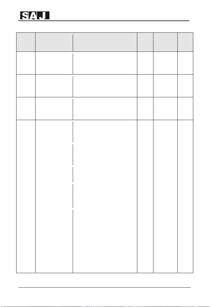
VM1000 Series
Function
code
F4.05
F4.06
F4.07
F4.08
F4.09
F4.10
F4.11
Description Set range Unit Default
Multi-point V/F
curve's frequency
point 2
Multi-point V/F
curve's voltage
point 2
Multi-point V/F
curve's frequency
point 3
Multi-point V/F
curve's voltage
point 3
Coefficient of slip
compensation in
V/F control mode
V/F over-excitation
gain
Oscillation
suppression
gain
F4.03~F4.07 0.01Hz 0.00Hz ★
0.0%~100.0% 0.10% 0.00% ★
F4.05~Motor rated
freqency(F2.04)
0.0%~100.0% 0.10% 0.00% ★
0.0%~200.0% 0.10% 0.00% ☆
0 ~ 200 1 64 ☆
0 ~ 100 1
0.01Hz 0.00Hz ★
Dependent
Rated
Model
Modifi
-cation
level
☆
F4.12
Voltage reference
in V/F seperation
mode
0: Digital Setting (F4.13)
1: AI1
2: AI2
3: Reserved
4: PULSE input(DI6)
5: Multi-step speed input
6:Simple PLC
7:PID
8:Communication, 100.0% refers
to motor rated voltage.
‐77‐
1 0 ☆

VM1000 Series
Function
code
F4.13
F4.14
F5.00
F5.01
F5.02
Description Set range Unit Default
Digital setting for
voltage reference in
V/F seperation
mode
Voltage rising time
for V/F seperation
mode
DI1 terminal
function
DI2 terminal
function
DI3 terminal
function
0V~Motor rated voltage 1V 0V ☆
0.0s~1000.0s
(Time from 0V to motor rated
voltage.)
F5 Group: Input Terminals Parameters
0: No function
1: Run forward(FWD)
2: Run reverse(REV)
3: 3-wire control
4: Jog forward (FJOG)
5: Jog reverse (RJOG)
6: UP command
7: DOWN command
8: Coast to stop
9: Fault reset (RESET)
10: Pause running
11: External fault input N. O.
12: Multi-step speed terminal 1
13: Multi-step speed terminal 2
14: Multi-step speed terminal 3
15: Multi-step speed terminal 4
16: Acceleration/Deceleration
Time Selection Terminal 1
17: Acceleration/Deceleration
Time Selection Terminal 2
18: : Frequency Reference
Switching Terminal
19: Reset UP/DOWN Frequency
Setting(Both keypad and
terminals)
0.1s 0.0s ☆
1 1 ★
1 2 ★
1 9 ★
Modifi
-cation
level
‐78‐

VM1000 Series
Function
code
F5.03
F5.04
F5.05
Description Set range Unit Default
20: Control Command Switching
Terminal 1
21: Acceleration/deceleration
prohibited
DI4 terminal
function
DI5 terminal
function
DI6 terminal
function
22: PID Control Pause
23:Simple PLC Running Status
Reset
24:Swing Frequency Pause
25: Counter Input
26: Counter Reset
27: Length Counting Input
28: Length Counting Reset
29: Torque Control Prohibit
30:PULSE Input(High Frequency
Input, DI6 terminal only)
31: Reserved
32: DC Brake Instantly
33: External Fault Input N.C.
34: Frequency Setting Taking
Effect(If no terminal is set to this
value, the function is in effect
defaultly)
35: PID Control Output Reverse
36: External Stop terminal 1
37: Control Command Switching
terminal 2
38: PID Integration Pause
39: Switching terminal, between
Frequency Reference X and Preset
Frequency
40: Switching terminal, between
Frequency Reference Y and Preset
Frequency
41~42: Reserved
43: PID Parameter Switching
Terminal
44: User Defined Fault 1
44: User Defined Fault 2
1 0 ★
1 0 ★
1 0 ★
Modifi
-cation
level
‐79‐

VM1000 Series
Function
code
F5.06
-F0.09
F5.10
F5.11~
F5.14
F5.15 DI filter time 0.000s~1.000s 0.001s 0.010s ☆
F5.16
F5.17
F5.18 AI1 lower limit 0.00V~F5.20 0.01V 0.00V ☆
Description Set range Unit Default
Reserved
VDI terminal
function
Reserved
Terminal control
mode
Frequency
changing rate
through UP/
DOWN terminal
adjusting
46: Speed/Torque Control Mode
Switching
47: Emergency Stop
48: External Stop Terminal 2
49: Decelerating and DC Braking
50: Time Clearing of Present
Running
51~59: Reserved
0: 2-wire control mode 1
2: 2-wire control mode 2
3: 3-wire control mode 1
4: 3-wire control mode 2
0.01Hz~ 6553.5Hz 0.01Hz 0.10Hz ☆
1 0 ★
1 0 ★
Modifi
-cation
level
Setting value
F5.19
corresponding to
AI1 lower limit
F5.20 AI1 upper limit F5.18 ~ +10.00V 0.01V 10.00V ☆
Setting value
F5.21
corresponding to
AI1 upper limit
F5.22 AI1 filter time 0.00s ~ 10.00s 0.01s 0.10s ☆
-100.0% ~ +100.0% 0.10% 0.00% ☆
-100.0% ~ +100.0% 0.10% 100.00% ☆
‐80‐

VM1000 Series
Function
code
F5.23 AI2 lower limit 0.00V ~ F5.25 0.01V 0.00V ☆
F5.24
F5.25 AI2 upper limit F5.23 ~ +10.00V 0.01V 10.00V ☆
F5.26
F5.27 AI2 filter time 0.00s ~ 10.00s 0.01s 0.10s ☆
F5.28
F5.29
F5.30
F5.31
Description Set range Unit Default
Setting value
corresponding to
AI2 lower limit
Setting value
corresponding to
AI2 upper limit
PULSE input lower
limit
Setting value
corresponding to
PULSE input lower
limit
PULSE input upper
limit
Setting value
corresponding to
PULSE input upper
limit
-100.0% ~ +100.0% 0.10% 0.00% ☆
-100.0% ~ +100.0% 0.10% 100.00% ☆
0.00kHz ~ F5.30
-100.0% ~ 100.0% 0.10% 0.00% ☆
F5.28 ~ 100.00kHz
-100.0% ~ 100.0% 0.10% 100.00% ☆
0.01kH
z
0.01kH
z
0.00kHz ☆
50.00kHz ☆
Modifi
-cation
level
F5.32 PULSE filter time 0.00s ~ 10.00s 0.01s 0.10s ☆
F5.33 DI1 ON delay 0.0s ~ 3600.0s 0.1s 0.0s ★
F5.34 DI2 ON delay 0.0s ~ 3600.0s 0.1s 0.0s ★
F5.35 DI1 OFF delay 0.0s ~ 3600.0s 0.1s 0.0s ★
‐81‐

VM1000 Series
Function
code
F5.36 DI2 OFF delay 0.0s ~ 3600.0s 0.1s 0.0s ★
F5.37
F5.38
F6.00
F6.01
F6.02
Description Set range Unit Default
0: High level
1: Low level
DI input ON
status setting 1
DI input ON status
setting 2
FM terminal output
selection
FMR open
collector output
function
Relay 1 output
function
Unit: DI1
Tens: DI2
Hundreds: DI3
Thousands: DI4
Tens thousands: DI5
0: High level
1: Low level
Unit: DI6
Tens: Reserved
Hundreds: Reserved
Thousands: Reserved
Tens thousands: Reserved
F6 Group: Output Terminals Parameters
0: Pulse output(FMP)
1: Open collector discrete
output(FMR)
0: No output
1: AC drive running
2: Fault output (stop)
3: Frequency-level detection
FDT1 output
4: Frequency reached
5: Zero-speed running (no output
at stop)
6: Motor overload pre-warning
7: AC drive overload pre-warning
8: Set count value reached
9: Designated count value reached
10: Length reached
11111 0 ★
11111 0 ★
1 0 ☆
1 0 ☆
1 2 ☆
Modifi
-cation
level
‐82‐

VM1000 Series
Function
code
F6.03
F6.04
~F6.05
F6.06
F6.07~
F6.10
Modifi
Description Set range Unit Default
11: PLC cycle complete
Relay 2 output
function
Reserved
VDO output
function
Reserved
12: Accumulative running time
reached
13: Frequency limited
14: Torque limited
15: Ready for Run
16: AI1>AI2
17: Frequency upper limit reached
18: Frequency lower limit reached
(no output at stop)
19: Undervoltage state output
20: Communication setting
21: Reserved
22: Reserved
23: Zero-speed running 2 (having
output at stop)
24: Accumulative power-on time
reached
25: Frequency level detection
FDT2 output
26: Frequency 1 reached
27: Frequency 2 reached
28: Current 1 reached
29: Current 2 reached
30: Timing reached
31: AI1 input limit exceeded
32: Load loss
33: Reverse running
34: Zero current state
35: Module temperature reached
36: Software current limit
exceeded
37: Frequency lower limit reached
(having output at stop)
38: Alarm output(Keep running)
39: Motor overheat warning
40: Current running time reached
41: User defined output 1
42: User defined output 2
1 1 ☆
1 0 ☆
-cation
level
‐83‐

VM1000 Series
Function
code
F6.11
F6.12 AO1 output options 1 0 ☆
F6.13 AO2 output options 1 1 ☆
Description Set range Unit Default
FMP output
options
0: Running frequency
1: Target frequency
2: Output current
3: Output torque
4: Output power
5: Output voltage
6: Pulse input( 100% correspond
to 100.0kHz)
7: AI1
8: AI2
9: Reserved
10: Length counting value
11: Couter value
12: Communication frequency
reference
13: Motor rotating speed
14: Output current( 100%
correspond to rated current)
15: Output voltage( 100%
correspond to rated voltage)
16: Reserved
1 0 ☆
Modifi
-cation
level
FMP output
F6.14
maximum
frequency
AO1 zero offset
F6.15
coefficient
F6.16 AO1 gain -10.00~10.00 0.01 1 ☆
F6.17
AO2 zero offset
0.01kHz~100.00kHz
-100.0%~100.0% 0.10% 0.00% ☆
-100.0%~100.0% 0.10% 0.00% ☆
0.01kH
z
50.00kHz ☆
‐84‐

VM1000 Series
Function
code
F6.18 AO2 gain -10.00~10.00 0.01 1 ☆
F6.19 FMR close delay 0.0s ~ 3600.0s 0.1s 0.0s ☆
F6.20 Relay 1 close delay 0.0s ~ 3600.0s 0.1s 0.0s ☆
F6.21 Relay 2 close delay 0.0s ~ 3600.0s 0.1s 0.0s ☆
F6.22 VDO close delay 0.0s ~ 3600.0s 0.1s 0.0s ☆
F6.23 FMR open delay 0.0s ~ 3600.0s 0.1s 0.0s ☆
F6.24 Relay 1 open delay 0.0s ~ 3600.0s 0.1s 0.0s ☆
F6.25 Relay 2 open delay 0.0s ~ 3600.0s 0.1s 0.0s ☆
F6.26 VDO open delay 0.0s ~ 3600.0s 0.1s 0.0s ☆
F6.27
Description Set range Unit Default
coefficient
0: Positive
1: Negtive
Output ON status
setting
Units: FMR
Tens: Relay 1
Hundreds: Relay 2
Thousands: Reserved
Ten thousands: Reserved
11111 0 ☆
Modifi
-cation
level
‐85‐

VM1000 Series
Function
code
F6.28
F6.29
F6.30
Description Set range Unit Default
0: Running frequency
1: Target frequency
2: DC bus voltage
3: Output voltage
4: Output current
Test value selection
for user defined
output (EX) 1
Comparison
method of user
defined output 1
User defined dead
interval 1
5: Output Power
6: Output torque
7~8: Reserved
9: AI1 input value
10: AI2 input value
11: Reserved
12: Couter value
13: Length counting value
Units: comparison test method
0: Equal(EX==X1)
1: Equal or greater than
2: Equal or less than
3: Interval comparison(X1 ≤
EX ≤ X2)
4: Bits test(EX & X1 = X2
Tens: Output method
0: False value output
1: True value output
0 ~ 65535 0 ☆
0 ☆
0 ☆
Modifi
-cation
level
F6.31
F6.32
User defined output
1 comparison value
X1
User defined output
1 comparison value
X2
0 ~ 65535 0 ☆
0 ~ 65535 0 ☆
‐86‐

VM1000 Series
Function
code
F6.33
F6.34
Description Set range Unit Default
0: Running frequency
1: Target frequency
2: DC bus voltage
3: Output voltage
4: Output current
Test value selection
for user defined
output (EX) 2
Comparison
method of user
defined output 2
5: Output Power
6: Output torque
7~8: Reserved
9: AI1 input value
10: AI2 input value
11: Reserved
12: Couter value
13: Length counting value
Units: comparison test method
0: Equal(EX==X3)
1: Equal or greater than
2: Equal or less than
3: Interval comparison(X3 ≤
EX ≤ X4)
4: Bits test(EX & X3 = X4
Tens: Output method
0: False value output
1: True value output
0 ☆
0 ☆
Modifi
-cation
level
F6.35
F6.36
F6.37
User defined dead
interval 2
User defined output
2 comparison value
X3
User defined output
2 comparison value
X4
0 ~ 65535 0 ☆
0 ~ 65535 0 ☆
0 ~ 65535 0 ☆
‐87‐

VM1000 Series
Function
code
F7.00
F7.01 MF.K key function
F7.02
F7.03
Description Set range Unit Default
F7 Group: Keypad & Display Interface Parameters
LCD yeypad
parameter copy
STOP/RESET key
stop function
Running status
LED display
selection 1
0: No operation
1: Local parameters will be copied
to LCD keypad
2: LCD keypad will download
parameters to local drive.
0: No function
1: Switching control command
source between keypad and
remote control(Remote control
include communication and
terminals command).
2: Switching rotation between
FWD & REV
3: Jog Forward
4: Jog Reverse
0: Only valid in keypad control
command mode
1: Always valid in any control
command mode
0000~FFFF
Bit00: Running frequency(Hz)
Bit01: Target frequency(Hz)
Bit02: DC bus voltage(V)
Bit03: Output voltage(V)
Bit04: Output current(A)
Bit05: Output Power(kW)
Bit06: Output torque(%)
Bit07: DI input status
Bit08: DO output status
Bit09: AI1 input value(V)
Bit10: AI2 input value(V)
Bit11: Reserved
Bit12: Counter value
Modifi
-cation
level
1 0 ●
1 0 ★
1 1 ☆
1111 17 ☆
‐88‐

VM1000 Series
Function
code
F7.04
Description Set range Unit Default
Bit13: Length counting value
Bit14: Load speed display
Bit15: PID setting value
0000~FFFF
Bit0: PID feedback
Bit1: Current step of PLC
running
Bit2: Feedback speed, unit 0.1Hz
Bit3: Feedback speed
Bit4: Running time left
Bit5: AI1 voltage before
correction
Bit6: AI2 voltage before
Running status
LED display
selection 2
correction
Bit7: Reserved
Bit8: Line speed
Bit9: Time since current power on
Bit10: Time of current running
Bit11: PULSE input frequency,
Unit 1Hz
Bit12: Setting of communication
Bit13: Reserved
Bit14: Master frequency reference
X display
Bit15: Auxiliary frequency
reference Y display
1111 0 ☆
Modifi
-cation
level
F7.05
Stop status LED
display selection
0000~FFFF
Bit00: Target frequency(Hz)
Bit01: DC bus voltage(V)
Bit02: DI input status
Bit03: DO output status
Bit04: AI1 input value(V)
Bit05: AI2 input value(V)
Bit06: Reserved
Bit07: Counter value
Bit08: Length counting value
‐89‐
1111 33 ☆

VM1000 Series
Function
code
F7.06
F7.07
F7.08
F7.09
F7.10 Product number - . ●
F7.11 Firmware version - . ●
Description Set range Unit Default
Bit09: Current step of PLC
running
Bit10: Load speed display
Bit11: PID setting value
Bit12: PULSE input frequency,
Unit 0.01kHz?
Load speed display
ratio
Heat sink
temperature of
inverter Power
module
Heat sink
temperature of
rectifier bridge
Accumulative
running time
0.0001 ~ 6.5000 0.0001 0.3 ☆
0.0℃~ 100 ℃ 0.1℃ . ●
0.0℃~ 100 ℃ 0.1℃ . ●
0h ~ 65535h 1h . ●
Modifi
-cation
level
F7.12
F7.13
F7.14
Number of decimal
places
for load speed
display
Accumulative
power-on time
Accumulative
consumed electric
energy(kWh)
0: 0 decimal place
1: 1 decimal place
2: 2 decimal places
3: 3 decimal places
0h~65535h 1h . ●
0~65535 kWh 1kWh . ●
1 0 ☆
‐90‐
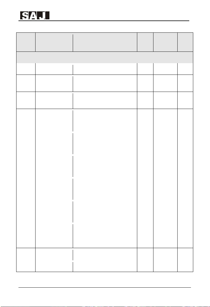
VM1000 Series
Function
code
F8.00 Jog frequency 0.00Hz~Maximum Frequency 0.01Hz 2.00Hz ☆
F8.01
F8.02
F8.03 Acceleration time 2 0.0s ~ 6500.0s 0.1s
F8.04 Deceleration time 2 0.0s ~ 6500.0s 0.1s
F8.05 Acceleration time 3 0.0s ~ 6500.0s 0.1s
F8.06 Deceleration time 3 0.0s ~ 6500.0s 0.1s
Description Set range Unit Default
F8 Group: Auxiliary Function Parameters
Jog acceleration
time
Jog deceleration
time
0.0s ~ 6500.0s 0.1s 20.0s ☆
0.0s ~ 6500.0s 0.1s 20.0s ☆
Dependent
Dependent
Dependent
Dependent
Rated
Model
Rated
Model
Rated
Model
Rated
Model
Modifi
-cation
level
☆
☆
☆
☆
F8.07 Acceleration time 4 0.0s ~ 6500.0s 0.1s
F8.08 Deceleration time 3 0.0s ~ 6500.0s 0.1s
F8.09 Jump frequency 1 0.00Hz~Maximum Frequency 0.01Hz 0.00Hz ☆
F8.10 Jump frequency 2 0.00Hz~Maximum Frequency 0.01Hz 0.00Hz ☆
Rated
Model
Dependent
Rated
Model
Dependent
‐91‐
☆
☆

VM1000 Series
Function
code
F8.11
F8.12
F8.13 Reverse option
F8.14
F8.15 Droop control 0.00Hz~10.00Hz 0.01Hz 0.00Hz ☆
F8.16
F8.17
F8.18
Description Set range Unit Default
Jump frequency
width
FWD/REV
switchover dead
zone time
Carrier Frequency
adjusting by
temperature
Accumulative
power-on time
threshold
Accumulative
running time
threshold
Drive startup
protection
0.00Hz~Maximum Frequency 0.01Hz 0.00Hz ☆
0.0s~3000.0s 0.1s 0.0s ☆
0: Reverse allowed
1: Reverse Prohibited
0: Disable
1: Enable
0h ~ 65000h 1h 0h ☆
0h ~ 65000h 1h 65000h ☆
0: Disable
1: Enable
1 0 ☆
1 1 ☆
1 0 ☆
Modifi
-cation
level
F8.19
F8.20
F8.21
Frequency
detection value
(FDT1)
Frequency
detection
hysteresis (FDT 1)
Detection width of
frequency
reached
0.00Hz~Maximum Frequency 0.01Hz 50.00Hz ☆
0.0%~100.0% (FDT1 Level) 0.10% 5.00% ☆
0.0% ~ 100.0% (Maximum
frequency)
0.10% 0.00% ☆
‐92‐

VM1000 Series
Function
code
F8.22
F8.23
F8.24
F8.25
F8.26
Description Set range Unit Default
Jump frequency
validity during
acceleration/decele
ration
Option as
accumulative
running time
reached
Acting option as
accumulative
power-on time
reached
Frequency point for
switchover
between
acceleration time 1
and acceleration
time 2
Frequency point for
switchover
between
deceleration time 1
and deceleration
time 2
0: Invalid
1: Valid
0: operation continue
1: Error code alarm
0: operation continue
1: Error code alarm
0.00Hz~Maximum Frequency 0.01Hz 0.00Hz ☆
0.00Hz~Maximum Frequency 0.01Hz 0.00Hz ☆
1 0 ☆
1 0 ★
1 0 ★
Modifi
-cation
level
F8.27
F8.28
F8.29
Terminal jogging
priority
Frequency
detection value
(FDT2)
Frequency
detection
hysteresis (FDT 2)
0: Disable
1: Enable
0.00Hz~Maximum Frequency 0.01Hz 50.00Hz ☆
0.0%~100.0% (FDT2 Level) 0.10% 5.00% ☆
1 1 ☆
‐93‐

VM1000 Series
Function
code
F8.30
F8.31
F8.32
F8.33
F8.34
F8.35
F8.36
F8.37
Description Set range Unit Default
Given frequency
reached 1
Given frequency
reached detection
width 1
Given frequency
reached 2
Given frequency
reached detection
width 2
Zero current
detection level
Zero current
detection time
Programm over
current setting
Programm over
current detection
time
0.00Hz~Maximum Frequency 0.01Hz 50.00Hz ☆
0.0%~100.0% (Maximum
frequency)
0.00Hz~Maximum Frequency 0.01Hz 50.00Hz ☆
0.0%~100.0% (Maximum
frequency)
0.0%~300.0%, 100.0% is
corresponding to motor rated
current, No output in stop status.
0.01s ~ 600.00s 0.01s 0.10s ☆
0.0%: No detection
0.1%~300.0% Motor rated current
0.00s ~ 600.00s 0.01s 0.00s ☆
0.10% 0.00% ☆
0.10% 0.00% ☆
0.10% 5.00% ☆
0.10% 200.00% ☆
Modifi
-cation
level
F8.38
F8.39
F8.40
Given current
reached 1
Given current
reached detection
width 1
Given current
reached 2
0.0% ~ 300.0% Motor rated
current
0.0% ~ 300.0% Motor rated
current
0.0% ~ 300.0% Motor rated
current
‐94‐
0.10% 100.00% ☆
0.10% 100.00% ☆
0.10% 100.00% ☆

VM1000 Series
Function
code
F8.41
F8.42 Timing operation
F8.43 Timing reference
F8.44 Timing setting 0.0Min ~ 6500.0min 0.1min 0.0min ☆
F8.45
F8.46
F8.47
F8.48
Description Set range Unit Default
Given current
reached detection
width 2
AI1 input voltage
lower limit
AI1 input voltage
upper limit
inverter Power
module
temperature
reached
Rapid current
limiting function
0.0% ~ 300.0% Motor rated
current
0: Disable
1: Enable
0: F8.44 Timing setting
1: AI1
2: AI2
3: reserved
0.00V~F8.46 0.01V 3.10V ☆
F8.45~10.00V 0.01V 6.80V ☆
0 ~100 ℃℃ 1℃ 75℃ ☆
0: Disable
1: Enable
0.10% 100.00% ☆
1 0 ☆
1 0 ☆
1 1 ☆
Modifi
-cation
level
F9 Group: PID parameters
0: Preset value(F9.01)
PID reference
F9.00
source
F9.01 PID preset value 0.0%~100.0% 0.10% 50.0% ☆
1: Analog terminal AVI
2 Analog terminal ACI
3: Communication interface
4: Muli-function digital input
terminals
1 0 ☆
‐95‐

VM1000 Series
Function
code
F9.02
F9.03
F9.04
F9.05
F9.06 Integral time I1 0.01s~10.00s 0.01s 2.00s ☆
F9.07
F9.08
Description Set range Unit Default
0: AI1
1: AI2
2: Reserved
PID feedback
selection
PID control
characteristic
PID reference &
feedback range
Proportional gain
P1
Differential time
D1
PID reverse
output frequency
limit
3: AI1-AI2
4: PULSE input(DI6)
5: Communication
6: AI1+AI2
7: MAX(|AI1|, |AI2|)
8: MIN(|AI1|, |AI2|)
0: Positive
1: Negative
0 ~ 65535 1 1000 ☆
0.0~100.0 0.1 20 ☆
0.000s~10.000s 0.001s 0.000s ☆
0.00~Maximum frequency 0.01Hz 2.00Hz ☆
1 0 ☆
1 0 ☆
Modifi
-cation
level
F9.09
F9.10
F9.11
F9.12
PID control
deviation limit
PID differential
limit
PID reference
gradual effect time
PID feedback filter
time
0.0%~100.0% 0.10% 0.00% ☆
0.00%~100.00% 0.01% 0.10% ☆
0.00~650.00s 0.01s 0.00s ☆
0.00~60.00s 0.01s 0.00s ☆
‐96‐

VM1000 Series
Function
code
F9.13
F9.14
F9.15 Integral time I2 0.01s~10.00s 0.01s 2.00s ☆
F9.16
F9.17
F9.18
F9.19
F9.20
Description Set range Unit Default
PID output filter
time
Proportional gain
P2
Differential time
D2
PID control
parameter
switching function
PID control
parameter
switching deviation
1
PID control
parameter
switching deviation
2
PID initial output
value
0.00~60.00s 0.01s 0.00s ☆
0.0~100.0 0.1 20 ☆
0.000s~10.000s 0.001s 0.000s ☆
0: No switching
1: Switching by DI terminal
2: Switching by deviation
0.0%~F9.19 0.10% 20.00% ☆
F9.18~100.0% 0.10% 80.00% ☆
0.0%~100.0% 0.10% 0.00% ☆
1 0 ☆
Modifi
-cation
level
F9.21
F9.22
F9.23
PID initial output
time
Maximum positive
deviation limit of
output interval
Maximum positive
deviation limit of
output interval
0.00~650.00s 0.01s 0.00s ☆
0.00% ~ 100.00% 0.01% 1.00% ☆
0.00%~100.00% 0.01% 1.00% ☆
‐97‐

VM1000 Series
Function
code
F9.24 PID integral option
F9.25
F9.26
F9.27 PID option at stop
F9.28
F9.29
F9.30 PID sleeping delay 0.0~3600.0s 0.1s 3.0s ☆
Description Set range Unit Default
Units: Seperated Integral
calculation
0: Disable
PID feedback loss
detection
PID feedback loss
detection time
PID auxiliary
function
PID sleeping
threshold
1: Enable
Tens: Output reaching limit and
stopping integral
0: Continue integral
1: Stop integral
0.0%: No detection
0.1% ~ 100.0%
0.0s~20.0s 0.1s 0.0s ☆
0: No calculation cotinue at stop
1: Calculation continue at stop
0: Normal PID
1: PID with sleeping function
0.0%~100.0% 0.10% 60.00% ☆
11 0 ☆
0.10% 0.00% ☆
1 0 ☆
1 0 ☆
Modifi
-cation
level
PID wakeup
F9.31
threshold
F9.32 PID wakeup delay 0.0~3600.0s 0.1s 3.0s ☆
FA Group: Protection Parameters and Fault Record
Motor overload
FA.00
protection
Motor overload
FA.01
protection gain
0.0%~100.0% 0.10% 20.00% ☆
0: Disable
1: Enable
0.20~10.00 0.01 1 ☆
1 1 ☆
‐98‐

VM1000 Series
Function
code
FA.02
FA.03
FA.04
FA.05
FA.06
FA.07
FA.08
FA.09
Description Set range Unit Default
Motor overload
warning coefficient
Over-voltage stall
gain
Over-voltage stall
protection voltage
Over-current stall
gain
Over-current stall
Protection currnet
Protecton against
short-circuit to
ground at power on
Fault auto reset
times
Options for fault
output DO during
fault auto reset
50%~100% 1% 80% ☆
0~100 1 0 ☆
120%~150% 1% 130% ☆
0~100 1 20 ☆
100%~200% 1% 150% ☆
0: Disable
1: Enable
0~20 1 0 ☆
0: Disable
1: Enable
1 1 ☆
1 0 ☆
Modifi
-cation
level
FA.10
FA.11
FA.12
Fault auto reset
interval
Input phase-loss
protection
Output phase-loss
protection
0.1s~100.0s 0.1s 1.0s ☆
0: Disable
1: Enable
0: Disable
1: Enable
1 1 ☆
1 1 ☆
‐99‐
 Loading...