


PDS33 Solar Pump
Controller
User Manual
Version code:PDS33-EN-60200589-1701

PDS33 Series
- 1 -
Preface
Thank you for using PDS33 series products. This manual provides you with relevant
operation instructions and detailed description of parameters. Please read this
manual carefully before installation, running, maintenance or inspection.
Please make sure the wiring and the pump’s rotation direction is correct before use.

PDS33 Series
- 2 -
Content
Preface ............................................................................................................... - 1 -
Notes for Safe Operation .................................................................................. - 4 -
Chapter 1 How It Works .................................................................................. - 6 -
1.1 Features ...................................................................................................................... - 8 -
Chapter 2 General Information .................................................................... - 10 -
2.1 Inspection ................................................................................................................. - 10 -
2.2 Descriptions and Features
........................................................................................ - 10 -
2.3 Protection Features
.................................................................................................... - 11 -
2.4 PDS33 Solar Pump Controller Model Description
.................................................. - 12 -
2.5 Outline &Installation Dimensions
........................................................................... - 16 -
Chapter 3 Mechanical and Electrical Installation ....................................... - 19 -
3.1 Mechanical Installation ............................................................................................ - 19 -
3.2 Electrical Installation
............................................................................................... - 20 -
Chapter 4 Start-up and Operation ................................................................ - 26 -
4.1 Keypad Description .................................................................................................. - 26 -
4.2 Keypad Operation Process
....................................................................................... - 27 -
4.3 Trial operation
.......................................................................................................... - 28 -
4.4 Running status panel display parameters
................................................................. - 29 -
4.5User Definable Parameters
....................................................................................... - 29 -
Chapter 5 Diagnostics and T r oubleshooting ................................................. - 35 -
5.1 Fault Codes ............................................................................................................... - 35 -

PDS33 Series
- 3 -
5.2 Common Faults and Remedies ................................................................................ - 39 -
Chapter 6 Regular maintenance .................................................................... - 41 -
6.1 Controller and Pump ................................................................................................ - 41 -
6.2 Solar panels
.............................................................................................................. - 41 -
6.3 Cable
......................................................................................................................... - 41 -
Chapter 7 Backup AC power ......................................................................... - 42 -

PDS33 Series
- 4 -
Notes for Safe Operation
■Before Installation
WARNING
Do not install or operate the controller that is damaged or has missing parts. Otherwise, it
may result in equipment damage or harm life.
■ Installation
CAUTION
◎ Hold the bottom of the controller when installing or moving the controller, can not just
hold the shell to prevent the injured or broken controller.
◎ Install the controller on nonflammable material like metal. Otherwise it may cause a
fire.
◎ When the controller is mounted in a protectiv e cabinet, the cabinet need to set vents to
ensure ambient temperature is below40℃,otherwise it may be damaged because of high
temperature.
◎Avoid direct sunlightwhen installing the controller, it can be installed under the PV array.
WARNING
◎Ensure only qualified personnel to operate. Otherwise it can cause an el ectrical shock or
damage of the controller.
◎ Make sure the controller is isolated from power supply by the circuit breaker. Otherwise it
may cause a fire.
◎ Make sure that the ground terminal is grounded correctly.
◎ Do not touch the power input terminals of the controller and the output terminalsfor
pump . Otherwise it may cause an electrical shock.

PDS33 Series
- 5 -
■ Operation
CAUTION
◎ Do not open or remove the front cover when operation. Otherwise it may cause an
electrical shock.
◎ Before testing the pump must be installed; can not make the pump dry-
run for a long
time .In order to test the pump, the maximum dry-run tim e i s not more than 15s
◎ If the pump turning is reversed, change any two lines of the pump’s three power lines.
◎ When the water pump stops due to the light shadow, it will restart the op eration after
120s.
◎ If a water level probe is installed in the well, when the water level is belo w the level o f
water shortage, the water pump will stop. If there is no water level probe,or it is not used, the
controller terminal must be short.
■ Maintenance and check
WARNING
◎ Only qualified or authorized professional personnel can maintain, replace and inspect the
controller. Otherwise it may cause damage and injury.
◎ Wait at least 10 minutes after the power failure, or make sure thatthere is no residual
voltage before carry out maintenance and inspection, otherwise it may cause damage.
■ Others
WARNING
◎ If failing to follow these instructions, resulting in damage to the machine, can not enjo y
the warranty service.

PDS33 Series
- 6 -
Chapter 1How It Works
The PDS33 solar pumping system serves to provide water in remote applications
where electrical grid power is either unreliable or unavailable.The controller can
convert DC from the PV array to AC,and drive kinds of pumps. In sunny days, the
PDS33 solar pumping system can continuously pump water. The system without
batteries and other energy storage devices, it is recommended to take water pumped
to a reservoir for later use and water sources are those natural or special such as river,
lake, well or waterway, etc. A float switch can be installed in the water tower to
control the pump operation. And install a low-level probe in well to detect the well
water so that the pump will stop when thewater is shortage. Figure 1 shows a typical
diagram of a PDS33 solar pumping system. The major parts and components in the
system are listed after the diagram.
Figure 1 PDS33 solar pumping system
The PDS33 solar pumping system consists of:
A. Solar Array
B. DC Breaker or Disconnect Switch and Combiner Box
F. Water Tower
Float Switch
E. Well
Level Switch
D. Pump
A. PV Array
C. PDS33 Solar Pump Controller
B. DC Breaker

PDS33 Series
- 7 -
C. PDS33 series Solar Pump Controller
D. Pump and Motor
E. Water Source Level Switches (optional)
F. Tank Level Switches (optional)
The PDS33 solar pump controller runs at variable speed while match the changing
power provided by the solar array. Variable speed operation means there is no
in-rush or surge of energy during the pump/motor start-up, helping to eliminate wea r
on the motor and pumping system.
Pump Check Valve Requi re m ent s
Notice: In order to ensure maximum system reliability and water delivery, check
valves must be installed in the drop pipe. The first check valve must be installed at
the pump and additional check valves should be installed every 30m (100 ft) of
vertical pipe after the pump.

PDS33 Series
- 8 -
1.1 Features
System Diagnostics
The PDS33 solar pump controller continuously monitors system performance and
detects a variety of abnormal conditions. In many cases, the controller will
compensate as needed to maintain continuous system operation; however, if there
is high risk of equipment damage, the controller will protect the system and display
the fault condition. If possible, the controller will try to restart itself when the fault
condition subsides. See Diagnostics and Troubleshooting section for a list of Fault
Codes and corrective actions.
Motor Soft-Start
Normally, when there is a demand for water and power is available, the PDS33
solar pump controller will be operating. Whenever the PDS33 solar pump
controller detects a need for water, the controller always “ramps up” the motor
speed while gradually increasing motor voltage, resulting in a cooler motor and
lower start-up current compared to conventional water systems. Due to the
controller’s soft-start feature this will not harm the motor.
Over Temperature Foldback
The PDS33 solar pump controller is designed for full power operation from a solar
array in ambient temperatures up to 45°C.In excess of 45℃ temperature conditions,
the controller will reduce output power in an a ttempt to avo id shutdown. Ful l power
output is restored when the controller temperature cools to a safe level.
Level Control Switch
The PDS33 solar pump controller can access two water level switch to 8tremote
control of the pump automatically. Level switch or PDS33 solar pump controller is
optional, not mandatory.

PDS33 Series
- 9 -
Switching to Backup AC Pow er
The PDS33 solar pump controller’s input power terminal may be switched manually
to a backup AC power source.
Note: Depending on the model number, PDS33 solar pump controllers support
power input either 220VAC single phase, or 380VAC three phase, Please contact
controller manufacturer or authorized agencies for details.
When the system is running on back-up AC power, please check for sufficient DC
primary source power every 30 minutes. If the primary DC power is available, shut
down the controller, switch back to primary power and attempt to run on DC
power supply.
NOTICE :A DC circuit switch and a generator power switch must be installed, and
these two switches must be mechanically interlocked each other to prevent
switching on together resulting the solar PV and the generator being connected to
the solar PDS33 solar pump controller simultaneously! Please check if the design is
in accordance with all applicable national and local electrical codes.

PDS33 Series
- 10 -
Chapter 2 General Information
The PDS33 solar pump controller is a variable speed motor drive designed to run
any IEC three-phase asynchronous motor. The PDS33 solar pumping system
provides water to remote locations by converting high voltage, dir ect current from a
solar array into alternating current to run a standard three-phase asynchronous motor.
When solar power is not available, the controller can be switched manually to an
alternate single-phase or three-phase AC input such as a generator or inverter from
battery, if available. The controller provides fault detection, motor soft start, and
speed control. The PDS33 solar pump controller is designed to provide these
features with the plug and play ease of installation.
The PDS33 solar pump controller is designed with the high standard of reliability
expected of products. The controller attempts to drive the pump and motor to deliver
water even under adverse conditions, reducing output as necessary to protect the
system components from damage, and only shutting down in extreme cases. Full
operation is restored automatically whenever abnormal conditions subside.
2.1 Inspection
Before installation, inspect the PDS33 solar pump controller unit. Verify that the
part number is correct and that no damage has occurred during transportation.
NOTE: PDS33 solar pump controller is one component of a PDS33 solar pumping
system which has other two optional components, solar array and AC pump with
motor.
2.2 Descriptions and Fea tures
The PDS33 solar pump controller is based on a standard PDS33 platform controlling
a standard three-phase asynchronous motor driving a pump powered b y a solar array
or an optional AC generator backup.

PDS33 Series
- 11 -
The PDS33 solar pump controller continuously monitors system performance and
incorporates a number of features for pumping system protection. In the event of a
fault, the PDS33 solar pump controller will indicate the type of fault through the
LED display mounted on the front cover of controller.
The PDS33 solar pumping system is optimized for pumping under adverse input
power conditions unique to solar arrays:
• Internal diagnostics will tolerate a lower input voltage.
• Whenever possible, the controller attempts to drive the pump load by maximizing
power output from the solar array.
•An easy way to use interface is to enhance configurability and enable remote
system monitoring.
• A LED display provides a detailed indication of system status.
• A small keypad offers flexibility for selection of user options.
2.3 Protection Features
Electronic monitoring gives the controller the capability to monitor the system and
automatically shut down in the event of:
• Dry well conditions – with low level switch
• Bound pump – with auto-reversing torque.
• High Voltage Surge
• Low Input Voltage
• Open motor circuit
• Short circuit
• Over heat
NOTE: This controller provides motor overload protection by preventing motor
current from exceeding rating current and by limiting the duty cycle in the event of
low water level. This controller does not provide over temperature sensing of the
motor.
PDS33 Series
- 12 -
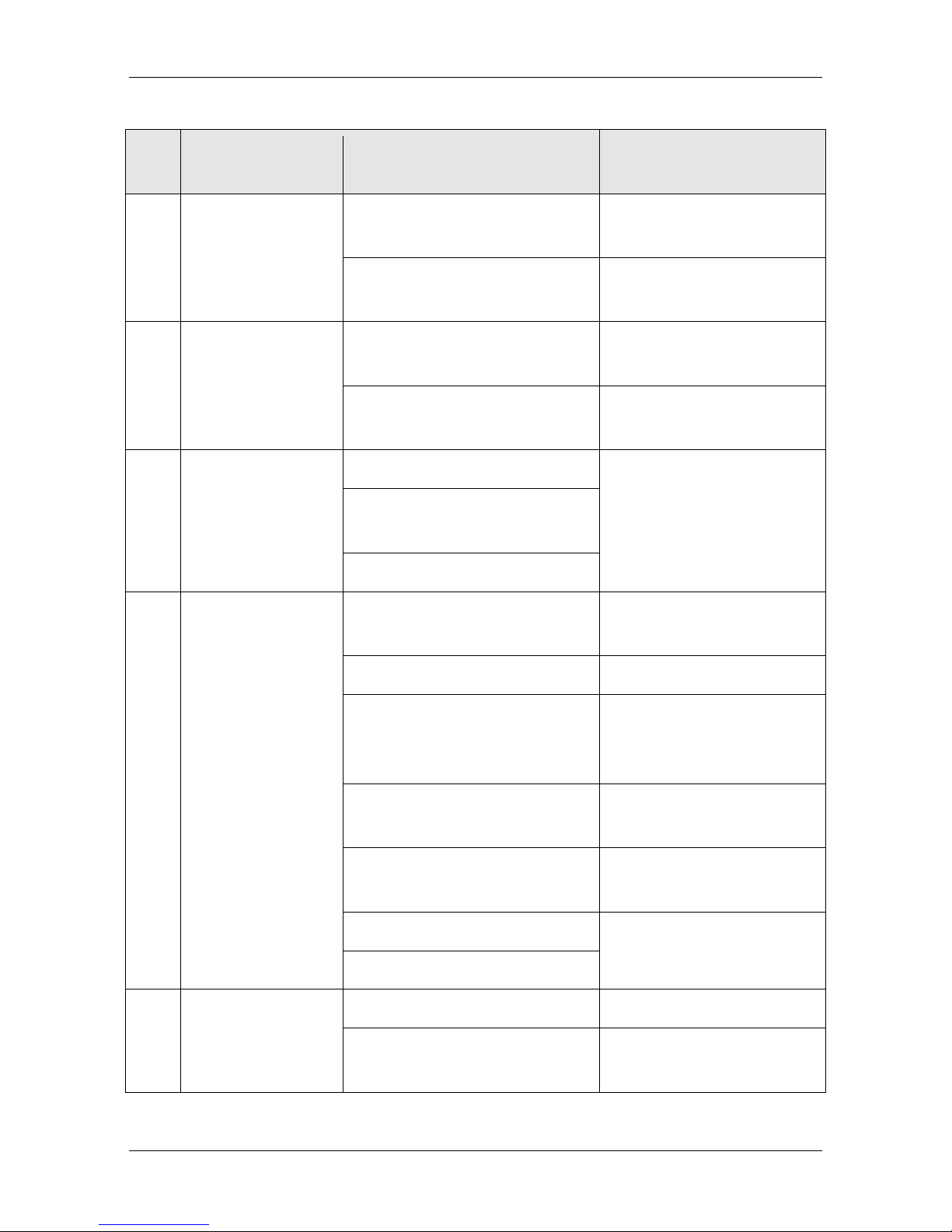
2.4 PDS33 Solar Pump Controller Model Description
2.4.1 Model Description
PDS33 -
① ② ③④⑤
4T5R5
Segment Description Options
①
PDS series
②
Series ID
3: Series of 3rd generation.
3: Apply to three-phase induction motor
③
Rated Output
Voltage
2: 220V three phase; 4: 380V three phase
④
Input Voltage
S: 310VDC rating, M PPT range 280VDC~360VD C(Note 1)
T: 540VDC rating, MPPT range 500VDC~700VDC(Note 2)
⑤
Motor Power Rating 004:4kW;5R5:5.5kW;R: decimal point
Note 1: Supporting Alternating Current i nput, with voltage ra t i ng of 220VAC single phase connected
to terminal R&T.
Note 2: Supporting Alte rnating Cur rent inp ut, with vo ltage ra ting of 380VA C three phase conne cted to
terminal R, S and T.
2.4.2 PDS33 Solar Controller General Parameters
General Parameters
Protection
Surge Protection Integrated Overvoltage Protection Integrated
Under voltage Protection Integrated Locked pump Protection Integrated
Open circuit Protection Integrated Short circuit Protection Integrated
Overheated Protection Integrated Dry Run Protection Integrated
Communication
RS485 Isolation RS485
GPRS Optional
Others
Ambient Tempera t ur e Range -20°C~60°C;>45°C, Derating as Required
Cooling Method Fan Cooling
Ambient Humidity ≤ 95%RH
Standard Warranty(month) 18
Certificates
IEC/EN 61800-5-1,IEC/EN 61800-2:2004,IEC/EN61800-3:2004,CE

PDS33 Series
- 13 -
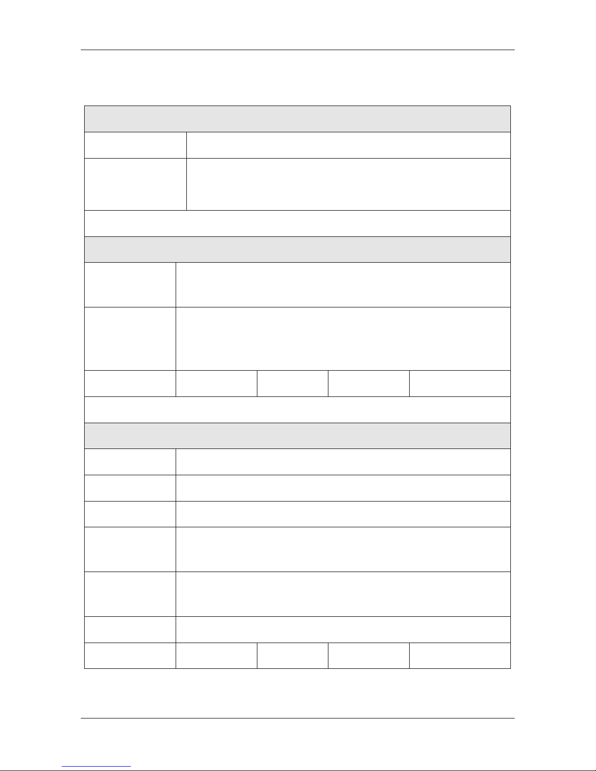
2.4.3 PDS33 Solar Pump Controller Input and Output Dat a
PDS33-2SXX/4TXX Input and Output Data
Controller Model
PDS33-2S2R2 PDS33-4T2R2 PDS33-4T004 PDS33-4T5R5
Input Data
Max Input Voltage(Voc) DC 450V DC 800V
Recommended Voltage, at MPP DC 280-360V DC 500-700V
Recommended PV Array Power [kW] 2.7~3.5 2.7~3.5 4.8~6.4 6.6~8.8
Alternate AC Generator
Input Voltage AC 220V(±10%) Three Phase AC 380(±15%)
Max Amps(RMS)[A] 23 5.8 10.5 14.6
Power and VA Capabil i t y[kVA] 4 4 5.9 8.9
Output Data
Output Voltage, Rated AC 220V(±10%) Three Phase AC 380(±15%)
Max Amps(RMS)[A] 10 5.1 9 13
Output Power, Ra t ed[ kW] 2.2 4 5.5 7.5
Output Frequency 0~50Hz/60Hz
Controller Model PDS33-4T7R5 PDS33-4T011 PDS33-4T015 PDS33-4T18R5
Input Data
Max Input Voltage(Voc) DC 800V
Recommended Voltage, at MPP DC 500-700V
Recommended PV Array Power[kW]
9~12
13.2~17.6 18~24 22.2~29.6
Alternate AC Generator
Input Voltage Three Phase AC 380V(±15%)
Max Amps(RMS)[A] 20.5 26 35 38.5
Power and VA Capability[kVA] 11 17 21 24
Output Data
Output Voltage, Rated Three Phase AC 380V(±15%)
Max Amps(RMS)[A] 17 25 32 37
Output Power, Rated[kW] 7.5 11 15 18.5
Output Frequency
0~50Hz/60Hz

PDS33 Series
- 14 -
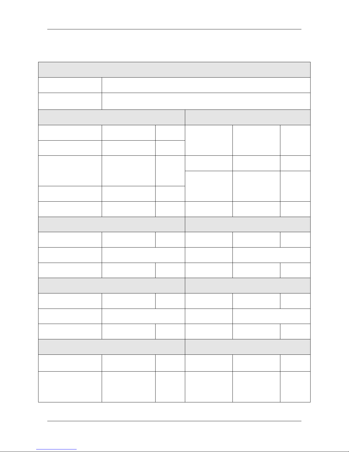
Controller Model PDS33-4T022 PDS33-4T030 PDS33-4T037 PDS33-4T045
Input Data
Max Input Voltage(Voc) DC 800V
Recommended Voltage, at MPP DC 500-700V
Recommended PV Array Power[kW] 26.4~35.2 36~48 44~59.2 54~72
Alternate AC Generator
Input Voltage Three Phase AC 380V(±15%)
Max Amps(RMS)[A] 46.5 62 76 92
Power and VA Capability[kVA] 30 40 57 69
Output Data
Output Voltage, Rated Three Phase AC 380V(±15%)
Max Amps(RMS)[A] 45 60 75 91
Output Power, Rated[kW] 22 22 30 37
Output Frequency
0~50Hz/60Hz
Controller Model PDS33-4T055 PDS33-4T075 PDS33-4T093 PDS33-4T110
Input Data
Max Input Voltage(Voc) DC 800V
Recommended Voltage, at MPP DC 500-700V
Recommended PV Array Power[kW] 66~88 90~120 112~149 132~176
Alternate AC Generator
Input Voltage Three Phase AC 380V(±15%)
Max Amps(RMS)[A] 113 157 180 214
Power and VA Capability[kVA] 85 114 134 160
Output Data
Output Voltage, Rated Three Phase AC 380V(±15%)
Max Amps(RMS)[A] 112 150 176 210
Output Power, Rated[kW] 55 75 93 110
Output Frequency
0~50Hz/60Hz
PDS33 Series
- 15 -
Controller Model PDS33-4T132 PDS33-4T160 PDS33-4T200 PDS33-4T220
Input Data
Max Input Voltage(Voc) DC 800V
Recommended Voltage, at MPP DC 500-700V
Recommended PV Array Power[kW] 159~211 192~256 240~320 264~352
Alternate AC Generator
Input Voltage Three Phase AC 380V(±15%)
Max Amps(RMS)[A] 256 307 385 430
Power and VA Capability[kVA] 192 231 250 280
Output Data
Output Voltage, Rated Three Phase AC 380V(±15%)
Max Amps(RMS)[A] 253 304 377 426
Output Power, Rated[kW] 132 160 200 220
Output Frequency
0~50Hz/60Hz
Controller Model PDS33-4T250 PDS33-4T280 PDS33-4T315 PDS33-4T350
Input Data
Max Input Voltage(Voc) DC 800V
Recommended Voltage, at MPP DC 500-700V
Recommended PV Array Power[kW] 300~400 336~448 378~504 426~568
Alternate AC Generator
Input Voltage Three Phase AC 380V(±15%)
Max Amps(RMS)[A] 468 525 590 665
Power and VA Capability[kVA] 355 396 445 500
Output Data
Output Voltage, Rated Three Phase AC 380V(±15%)
Max Amps(RMS)[A] 465 520 585 650
Output Power, Rated[kW] 250 280 315 350
Output Frequency
0~50Hz/60Hz
Note: according to different regions, the recommended PV array power is 1.2 ~ 1.6
times the power of the controller.

PDS33 Series
- 16 -
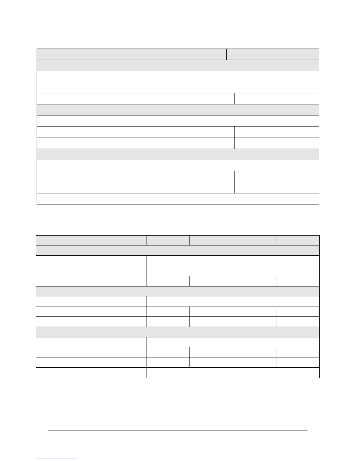
2.5 Outline &Installation Dimensions
Figure 2-1 2.2kW Outline &installation dimensions diagram
Figure 2-2 4-5.5kW Outline &installation dimensions diagram
Figure 2-3 7.5-11kW Outline &installation dimensions diagram
130
186
154.8
120
5.2
120
5.2
176
180.2
Φ5.5
150.5
231
241
162
150.5
5.5
195.4
348
360.5
182
156
323.5
Φ12
6.2
6.2
156

PDS33 Series
- 17 -
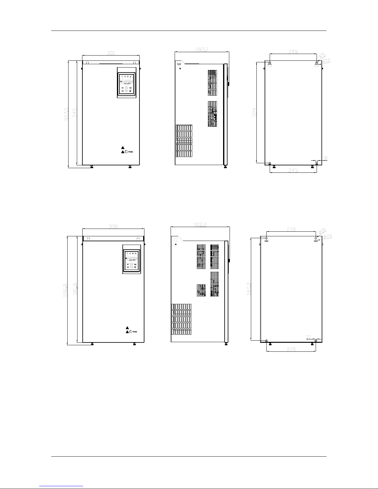
Figure 2-4 15-18.5kW Outline &installation dimensions diagram
Figure 2-5 22-30kW Outline &installation dimensions diagram
373
385.5
219
196.9
156
348.5
156
Φ12
6.2
6.2
199
406.5
7
Φ12
7
228.6
256
430
445
PDS33 Series
- 18 -
Figure 2-6 37-45kW Outline &installation dimensions diagram
Figure 2-7 55-93kW Outline &installation dimensions diagram

PDS33 Series
- 19 -
Chapter 3Mechanical and Electrical Installation
3.1 Mechanical Installation
3.1.1 Installation environment
Install the PDS33 solar pump controller in a control box with control terminals and
power wiring. Install the control box out of direct sunlight to prevent overheating
and reduced performance. The optimum location is on the mounting pole for the
solar array underneath the array for protection from the sun, heat, and weather
elements. Placing the control box in direct sunlight or high ambient temperatures
will result in poor performance due to temperature foldback protection of the PDS33
solar pump controller. For optimum performance, maximize the shading of the
control box.
It is recommended to use a wire tube to protect th e electric wire from the destruction
of wildlife and natural weathering, and bury the wire tube into the ground to
strengthen protection. Use a higher quality outdoor cableif there is no wire tube.
3.1.2 Location Selection
The PDS33 solar pump controller is intended for
operation in ambient temperatures up to 60℃, but
in order to avoid overheating, it is recommended to
install the controller in the shadow position.
Figure 3Control Box Location

PDS33 Series
- 20 -
The PDS33 solar pump controller must be installed into a control box which has a
tight enclosure to avoid direct sunshine,rain, dust, moistur e, animals, plan ts, etc. The
control box should have a bottom gland plate for installing wire cord or conduit. To
decide the size of control box, Please refer to the following Figure 4.
Figure 4Ventilation Arrangement and Required Distances
3.2 Electrical Installation
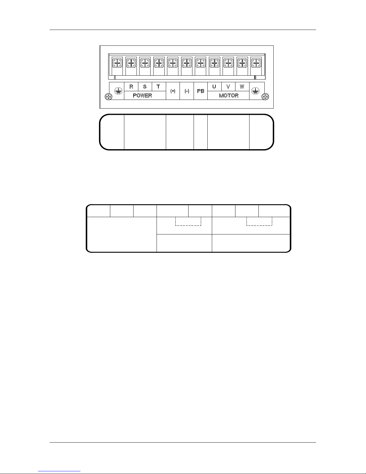
3.2.1 Terminals
The following are typical figures of terminal blocks.
Note: Terminals are different in shapes and combinations, depending on different si zes
of PDS33 Solar Pump Controllers.
隔热
导流板
PDS33 Series
- 21 -
Figure 5 Main terminals (The sequence may be different from actual product)
Figure6 Control terminals (The sequence may be different from actual product)
3.2.2 Power in DC Wiring
For Solar Pumping Systems, a two-pole DC disconnect switch must be installed
between the solar array and the PDS33solar pump controller.
Connect the cables which comes from the two-pole DC disconnect Switch down
stream terminals marked with “+” and “-” (positive and negative poles of Solar
panel output), to PDS33 solar pump controller’s terminals block labeled as “+”,
“-” .
Note: The R, S, T terminals are with anti reverse connection protection; DC power
supply can be connected with any two of R, S, T terminals, no need consider the
phase sequence.
GROUND
PowerIn
AC INPUT
The DC and AC can't
input at the same time
NO FUNCTION
Pump
To reverse direction
reverse any two wires
GROUND
DI1 DI2
DI3 COM DI4
DI5
DI6 COM
NC
N0
Remote Float Switch
Low-water
sensor probe
No Function
PDS33 Series
- 22 -
WARNING
Before connect DC wiring, following th e steps below to prevent hazardous electric shock
resulting in serious injury or device burning.
• Make sure that the external DC disconnect switch is off.
•To ensure that the polarity of the solar array cable must be properly connected to the
controller's +, - pole, otherwise possible damage the controller.
•Make sure that AC power is disconnected (If AC power supply is wired as backup
power,AC and DC power supply can no t simultaneously put into the controller, otherwise it
will damage the controller.)
3.2.3 Junction box connection
If there are a large number of solar modules, it is needed to use a junction box to
converge the bus to the solar array.The junction box need to install fuses, lightning
protection device and DC switch.The fuse and the DC switch can prevent the short
circuit protection; the lightning protection devi ce can play the direct current s ide the
lightning protection function. The junction box must be sealed, and water can not
enter
3.2.4 Ground Wiring
Ground terminal (GND) is labeled as this icon . Please refer to the instruction to
this icon, or other equivalent icon or sign by local electrical codes or international
standard. Correct grounding helps to prevent shock hazard if there is a fault in the
motor.
3.2.5 Motor Wiring
Connect the cable with four wires from the Motor to the controller terminal block to
terminals U, V, W, and GND (See Figure 9). Check motor lead color to ensure
correct installation.。
Note: To reverse direction of motor rotation, reverse any two wires
PDS33 Series
- 23 -
US Black(BLK) Red(RED) Yellow(YEL) Ground(GND)
International Gray(GRY) Black(BLK) Brown(BRN) Ground(GND)
Figure 7Motors with international leads
3.2.6Low water level prob e wiring (optional)
In order to avoid dry pumping lead to pump damage, it can be connected a wells
probe to the terminals of the PDS33 solar pump controller, so as to detect the water
level in wells and the wire maximum length can not be more than 50m. If there is
no water level probe for the detection of the water level, please keep the two
terminals of the controller short. The controller can also detect water through the
built-in software water detection function; see section 4.3.
3.2.7 Water tank level float wiring (optional)
Using a floating ball switch to prevent reservoir overflow is recommended. When
the reservoir is full, the pump will stop; when the water level is lower than the low
level, the pump will be restarted. It can prevent the overflow, limit the unnecessary
pump wear. The PDS33 controller allows the use of small si gnal line to conne ct to
remote float switch, even if the position of the reservoir is far away.
Figure 8FloatingBall Diagram
position
pump off
position
pump on
pumping
range
cable
weight
sealed
cable clamp
PDS33 Series
- 24 -
Floating ball switch request:
1. Three signal line
2. The minimum requirements for 1 mm² line diameter, the distance up to 600m
3. If the application is in a long distance transmission, the need to use the shielded
wire.The front-end of the shielding layer closes to the controller needs to be
grounded, while the back-end closes to the floating ball switch,which is not required
to be grounded.
If the float switch is not used, the DI6 and COM are kept short.
Figure 9 Float ball wiring diagram
3.2.8Electrical conduit
When the system installed outdoor, electrical conduit can be used to protect the
outdoor electric wires, so as to avoid the impact from the weather, human activities,
chewing animals.Us e the higher quality outdoor wireif there is no electrical conduit.
DI5 DI6 COM
NC
N0
Remote
Float
Switch
COM
Float Switch
N0
NC
COM
if cable is shielded,
ground this end only
UP: closed
DOWN: open
normal: open

PDS33 Series
- 25 -
3.2.9 System Wiring Diagram
Figure10System Wiring Diagram
NOTE:
1. The float switch is optional; if not use, please keep the terminal DI6 and COM
short.
2. Low water level probe is optional; if not use, ple ase keep the terminal DI4 and
COM short.
In the case of conventional 250W polycrystalline components, the peak voltage is
30.6V and the open circuit voltage is 37V. Description of the number of input
components in series:
The PDS33-2S series controller is connected in series with the serial number of the
input components of the 10~12 block, and the 250W 280~360VDC (MPPT) is
satisfied.
The PDS33-4T series controller is connected in series with the serial number of the
input components of the 18
~20 block, and the 250W 500~700VDC (MPPT) is
satisfied.
+ -
R S T
PB
U V W
COM DI4 DI5 DI6 COM
NC
N0
POWER MOTOR
GROUND
GROUND
Power In
The DC and AC
can't input at
the same time.
AC INPUT
To revers e directi on,
reverse any t wo wires
Pump
Low-wat er
sensor pr obe
Remote Float
Swi tch
PV Array
Earth Ground
Pump Motor
Submersibl e
Cable Splice
DC Swit ch
Low Wa te r
Level Probe
(opti onal)

PDS33 Series
- 26 -
Chapter 4 Start-up and Operation
4.1 Keypad Description
Figure 11 Keypad Schematic Diagram
Symbol
Button Name
Function Description
MENU
program/ exit key Enter or exit of menu, parameter modification
ENT
data enter key
Progressively enter menu and confirm parameter
▲
UP increase key Progressively increase data or function codes.
▼
DOWN decrease key Progressively decrease data or function codes.
SHIFT
shift key
Use it to select displayed parameters cyclically
during running or stop status. In parameter setting
mode, press this key to select the bit to be
modified.
PDS33 Series
- 27 -
RUN/STOP
Run/stop key
Start to run the controller in keypad control mode
and In running status, use it to stop the controller.
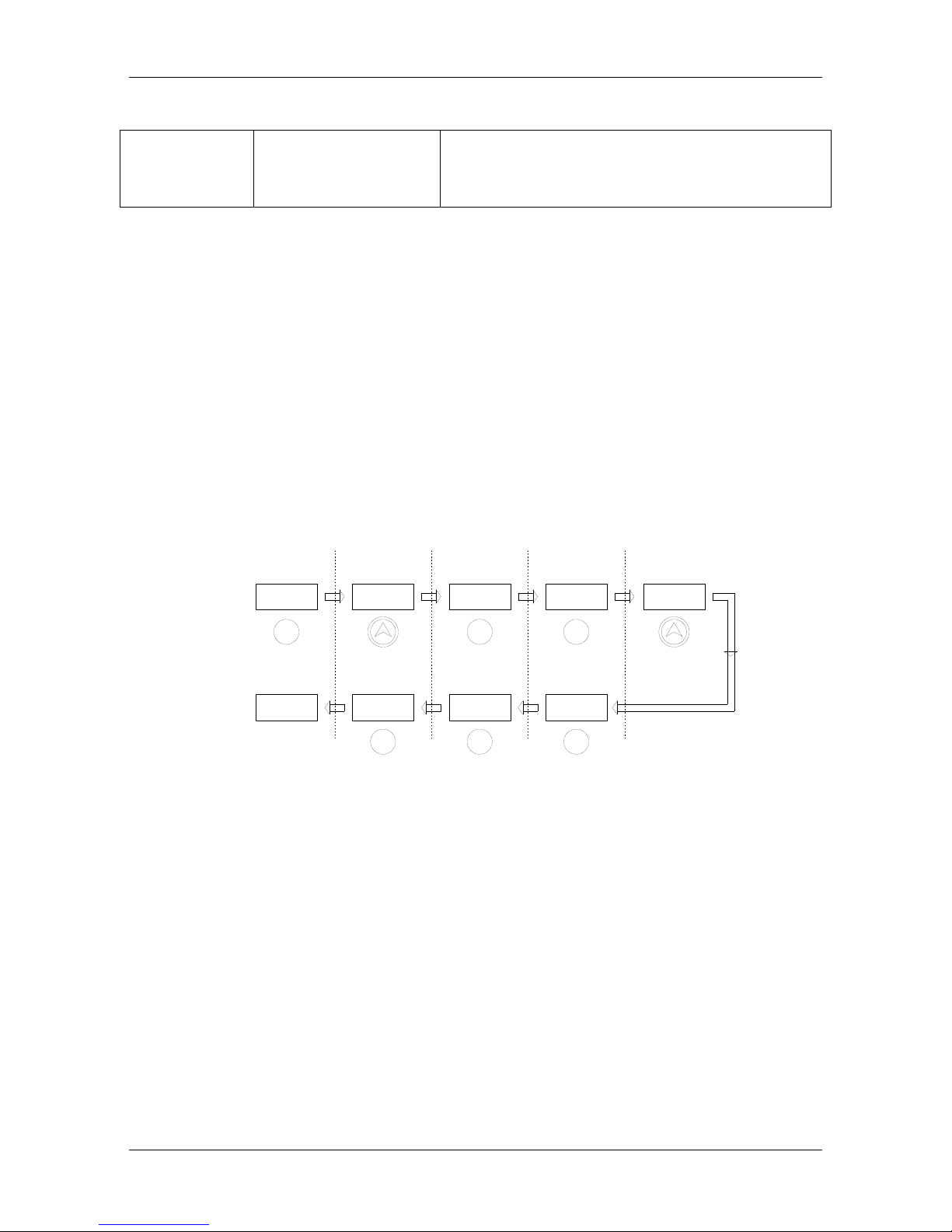
4.2 Keypad Operation Process
4.2.1 Parameter Setting
Three levels of menu are as following:
• Function code group (first-class)
• Function code (second-class)
• Setting parameter of function code (third-class)
In order to set up the electric automatic start function FD.07=11 as an example, the
modified parameter flow chart is as follows:
Figure12
Schematic Diagram of Function Parameters
4.2.2 Fault Reset
After the controller has failed, the controller will display the relevant fault code
information. The conventional fault code (E002/3/4/5/6/7/8/9/10/11/12/18) can
automatically reset after 10s operation, and can also choose to reset the
STOP/RESET on the keyboard. If the conventional failure persists, the controller
will reset once every 10s. Special fault code (E001/13/14) requires the user through
the STOP/RESET key on the keyboard to reset the f ault ; the controller can continue
to run after the reset.
Display
Reading:
Button:
Stand By Status
0.00
F0
First Class
FD
FD.07
MENU
ENT
First Class Second Class
0.00
FD
FD.10
11
10
Third Class
Run Status First Class Second Class Third Class
Value Now
New Value
ENT
(Frequency/HZ)
(Frequency/HZ)
Display
Reading:
Button:
ENT
MENU
MENU

PDS33 Series
- 28 -
4.3 Trial operation
●Check and make sure wiring are correct. If needed, take a megger to test the
insulation of motor, cable, etc.;
●Use a multimeter to test the PV output voltage at the DC switch.;
●Power on the controller by switch the DC switch.
●If necessary, modify and set the parameters of motor to the controller
For Example, if the motor which rated frequency is 60Hz, these parameters need
modification:
High limit of running frequency F0.12=60;
Other related parameters are: motor rated power F2.01, motor rated frequency
F2.02=60, motor rated speed F2.03, motor rated voltage F2.04, motor rated current
F2.05.
Note: default motor rated frequency setting is 50Hz.
Slowly start to check the direction
Pressing the RUN/STOP key to start the motor shortly and slowly, and check the
direction of the pump.
If the pump is in dry-run, the maximum operating time can not exceed 15seconds;
otherwise it may cause damage to the pump. If the pump steering error, close the DC
switch, according to the pump / motor wiring to change the wiring of the motor
section of the two leads.
After the above parts are complete, you can try to run the system.
Let the system work for an hour, check the water supply capacity.
Commissioning finish
When the light is insufficient, the solar power module output power will be
reduced, and the pump operation speed will be very slow until stop. The controller
will attempt to start every120s, and during the trial run, the running indicator is
always on.

PDS33 Series
- 29 -
When a shadow suddenly passes through the battery array, the controller will lose
track of the input voltage, and the pump will stop working. But the controller does
not show the fault, the controller will try to restart the pump.
4.4 Running status panel display parameters
Description: press "shift" key to switch
Display code Name Description Unit Remarks
H Operating Frequency The Operating Frequency Hz ◎
D Input Voltage DC Input Voltage V
A Running Current Controller Actual Output Current A ◎
P Input Power DC Input Power KW
4.5User Definable Parameters
○:The parameters can be modified at stop or running status.
●:The parameters cannot be modified at running status.
◎ The parameters which are act ual-detecting record value and cannot be modified.
Function
Code
Function Descriptions Unit Factory Setting
Modifica
tion Type
F0 Group: Basic Parameters
F0.01
Start/stop signal
option
0-2 \ 0 ●

PDS33 Series
- 30 -
Function
Code
Function Descriptions Unit Factory Setting
Modifica
tion Type
F0.12
High limit of
running frequency
30.00~60.00 Hz 50.00
〇
F0.14
Low limit of
running frequency
0.00~F0.12 Hz 20.00
F0.18
Acceleration time
0.1 ~3600
s
10.0
〇
F0.19 Deceleration time 0.1 ~3600 s 10.0
〇
F0.20 Default setting
0:Not restore to default
setting
1: Restore to factory setting
2:Fault record clearing
0 ●
F2 Group: Motor Parameters
F2.01 Motor rated power
0.4 ~400.0 kW
Different
according to
inverter model
●
F2.02
Motor rated
frequency
10.00 ~F0.10 Hz 50.00 ●
F2.03 Motor rated speed 0 ~36000 rpm
1500(Different
according to
inverter model)
〇
F2.04
Motor rated
voltage
0 ~480 V
Different
according to
inverter model
●
F2.05
Motor rated
current
0.8 ~2000 A
Different
according to
inverter model
●
F7 Group: Display Interface Parameters
F7.00 User password 0 ~9999 0
〇
F7.02
Manufacturer
debug
Reserved 0
〇
F7.09
Module
temperature
0 ~100.0
℃
●
PDS33 Series
- 31 -
Function
Code
Function Descriptions Unit Factory Setting
Modifica
tion Type
F7.10
Inverter firmware
version
◎
F7.11
Accumulative
running time
0 ~9999 hour
◎
FA Group: Protection and Malfunction Parameters
FA.14
Fault record of the
one before last
0: No fault
1: Inverter module protection
(E001)
2. Over-current when
accelerate (E002)
3: Over-current when
decelerate (E003)
4: Over-current at constant
speed (E004)
5: Over-voltage when
accelerate (E005 )
6: Over-voltage when
decelerate (E006)
7: Over-voltage at constant
speed (E007)
8:Hardware overvoltage
(E008)
9:Under voltage (E009)
10:Inverter overload ( E010)
11:Motor overload (E 011)
12:Phase-lack of input (E012)
13:Phase-lack of output
(E013)
14:Heatsink overheating
(E014)
15:External fault (E015)
16:Communication fault
(E016)
17:Reserved
18:Current detection fault
(E018)
20:Well level fault(E020)
21:Tank level fault(E021)
22:EEPROM fault (E022)
26:Water shortage fault
(E026)
◎
FA.15 Last fault record
〇
FA.16
Current fault
record
〇
PDS33 Series
- 32 -
Function
Code
Function Descriptions Unit Factory Setting
Modifica
tion Type
FA.17
Running
frequency when
fault occurs
Hz
◎
FA.18
Output current
when fault occurs
A
◎
FA.19
DC bus voltage
when fault occurs
V
◎
FD Group: Solar pumping special parameters
FD.07
Auto start when
power on
10:Disable
11:Enable
10
〇
FD.10
Water shortage
detection time
0~250 (0: disabled) s 10
〇
FD.11
Lowest running
frequency when
yielding water
0.00 ~F0.10 Hz 20.00
〇
FD.12
Water shortage
detection current
ratio
corresponding to
no-load current
80.0 ~300.0 % 150.00
〇
FD.13
Interval of water
shortage detection
1 ~9000 min 20
〇
FD.14
Upper limit of
MPPT voltage
250-FD.15
430-FD.15
VDC 275/500
〇
FD.15
Lower limit of
MPPT voltage
FD.14-450
FD.14-800
VDC 350/600
〇

PDS33 Series
- 33 -
Parameter interpretation:
F0.00, Start/Stop Mode Option:Set to 0, start-stop control of keyboard panel, set to 1, the
external terminal control start-stop, DI1 and COM conduction start, disconnected to stop;
F0.14, Low limit of running frequency: this parameter defaults to 20Hz, when the
light becomes weak, and the controller output frequency is lower than F0.14, the
controller will be in standby mode. After the light becomes strong, the controller
will rerun. Can set this parameter artificially, in order to avoid pump at low speed
without water, reduce the pump abrasion at low speed.
F2.01-F2.05,Motor parameter: the user can be set according to the actual pump
motor nameplate parameters
F7.00 user password: the user can set a 4 digits password;After the password is set
up and confirmed, the password will be valid for a minute.
FD.07, Automatic star t when power on: the factory defaults to 10 (disabled).It can
be set to 11 (enabled), then as long as the solar module power supply, the controller
will automatically start and achieve automatic operation of the whole day.
FD.10 water shortage detection time: when applied to a deep well pump, not using
the water level probe to detect the water shortage, the controller can use the built-in
water shortage detection function to complete the water shortage detection. When
this parameter is not 0, the software will start the function of water shortage.
Software shortage detection principle: If the water shortage happens, the controller
will still run FD.10 time, after that it will appear the water shortage fault E026.The
fault will be reset and the controller will restart automaticallyafter 20 minutes. If
there is no water shortage but fails E026, it may appear false; then you can simply
reduce FD.12 value.
Note:
FD. 14 and FD. 15 is working voltage range for MPPT, if appear E009 protection during
running, check the DC input voltage value of the machine, such as input voltage is 650 v, the
FD.15 can be modify to 750 v, then FD. 14 can be modify to 600 v.

PDS33 Series
- 34 -
WARNING: DO NOT touch any other piece inside the PDS33 Solar pump
controller while power is applied. To service any other areas of the controller,
disconnect ALL power sources and wait 5 minutes before continuing.
PDS33 Series
- 35 -
Chapter 5 Diagnostics and Troubleshooting
The PDS33 solar pump controller will attempt to drive the pump to deliver water
even under adverse conditions. To ensure years of reliable service, it must also
protect the system components from conditions that might result in equipment
damage. When adverse conditions arise, the controller will continue to deliver as
much water as possible by re duced output if necessary, and will shut down only in
extreme cases. Full operation will resume automatically whenever abnormal
conditions subside.
If the controller has stopped to indicate a fault code on the display, the associated
time-out delay will vary depending on the nature of the fault. The number following
the “E” symbol corresponds to the error code for the offending condition.
5.1 Fault Codes
Fault
code
Fault description Possible causes Remedy
E001 IGBT module fault
Too short acceleration time
Increase acceleration time
Damaged IGBT module
Ask for support
Malfunction caused by
interference
Inspect external equipment
and eliminate interference
Improperly grounding
Check grounding wire
E002
Over-current during
acceleration
Too fast acceleration
Increase acceleration time
Too low input voltage
Check the input power
supply or wiring
Lower-rating controller
Replace with higher-rating
controller
PDS33 Series
- 36 -
Fault
code
Fault description Possible causes Remedy
E003
Over-current during
deceleration
Too-fast deceleration Increase deceleration time
Too-heavy and large-inertia load Add proper braking units
lower-rating controller
Replace with higher-rating
controller
E004
Over-current at
constant running
speed
Sudden change of load Check the load
Too low input voltage
Check the input power
supply or wiring
Lower-rating controller
Replace with higher-rating
controller
E005
Over-voltage during
acceleration
Abnormal input voltage Check input power
Restart the motor when
instantaneous trip-off occurs
Avoid prompt restart when
trip-off
E006
Over-voltage during
deceleration
Too-fast deceleration Add proper braking units
Abnormal input voltage
Check input power supply or
wiring
E007
Over-voltage at
constant running
speed
Abnormal input voltage
Install proper input AC
reactor
E008
Hardware
over-voltage
Abnormal input voltage
Check input power supply or
wiring
Too-fast deceleration
Increase deceleration time
E009
Under voltage of
DC bus
Too-low input voltage
Check input power supply or
wiring
E010 Controller overload
Too fast acceleration Increase acceleration time
Restart the motor when
instantaneous trip-off occurs
Avoid prompt restart when
trip-off
PDS33 Series
- 37 -
Fault
code
Fault description Possible causes Remedy
Too-low input voltage
Check input power supply or
wiring
Too-heavy load
Replace with higher-rating
controller
E011 Motor overload
Too-low input voltage
Check input power supply or
wiring
Lower-rating controller
Replace with higher-rating
controller
E013 Output phase loss
Broken wires in the output cable
Check the wiring and
installation
Broken wires in the motor
winding
Loose output terminals
E014 Controller overheat
Instantaneous over-current of
controller
Refer to over-current remedy
Output short circuit
Re-wiring of output
Cooling fans of controller
stopped or damaged. Obstruction
of ventilation channel
Replace cooling fan and
clear the ventilation channel
Too-high ambient temperature
Decrease the ambient
temperature if possible
Loose cables or terminals
Inspect and tighten the wire
and terminals
Abnormal power circuit
Ask for support
Abnormal control PCB board
E016
Communication
fault
Improper baud rate setting
Set proper baud rate
Receive wrong data
Push STOP/RESET to reset
and ask for support

PDS33 Series
- 38 -
Fault
code
Fault description Possible causes Remedy
Long-time communication
interruption
Check communication
devices and cables
E018
Current detection
fault
Loose wires or connectors of
control board
Check the wiring and
connectors
Amplifying circuit abnormal
Ask for support
Hall sensor is damaged
Power circuit abnormal
E020 Well Level Fault Dry well or slow water recovery
Wait for water to recover or
reinstall the pump
E021
Tank Level Fault
before auto start
High level limit is reached.
Wait until water level comes
below the low level limit,
and then the PDS33 Solar
controller will start the pump
again
E022 EEPROM fault
Read/ Write fault of control
parameters
Push STOP/RESET to reset
EEPROM damaged
Ask for support
E026 Water shortage fault
Water shortage of water source
Stop the controller Repair
broken wiring or replace
water level switch
Verify if the setting of FD.12
"Water shortage detection current
ratio" is too high, while FD.10
"Water shortage detection time"
is non-zero and the current
sensing is enabled.
Reduce setting value of
FD.12

PDS33 Series
- 39 -
5.2 Common Faults and Remedies
The PDS33 solar pump controller may have following faults or malfunctions durin g
operation, please refer to the following remedies.
5.2.1 Pump can not run
The main problem of the new system is that the wiring is not standardized and the
controller terminal line falls,so that the pump cannot run. Sometimes the RUN
indicator light on the keyboard is bright, and the controller also has voltage
output,but may be the solar array does not have enough power to start the pump;
then the contro ller will attempt to start the pump every 120s. There are the following
reasons for the pump can not run:
① If there is no enough sun light, and the controller's input power is not enough.
② Motor wiring errors cause the pump to reverse, change the wiring.
③ The motor shaft vibrate sand can not rotate, it may be caused by the wiring
errors;Need to re check the motor wiring.
④ Pumps and pipes are clogged with mud and debris, and the pump can't run
5.2.2 Controller over current, overload fault(E002/3/4/10/11)
The controller appears over current and overload failure may be due to the following
reasons:
①The pump or pipe plug causes the pump current increase and the controller
protection; Need to pull out the pump and check
②Because of the increase in operating current of the pump, which is caused by the
too long pump wire, the controller will be protected, and the controller will be
enlarged to use.

PDS33 Series
- 40 -
5.2.3 DC switch trip when power on
① A multimeter can be used to check the internal circuit of the co ntroller, if there is
a short circuit, the machine has been damaged
②Check if the machine has a burning smell; if there is a burning smell, please
contact the agent to replace the controller
5.2.4 The keyboard without displ ay after power on
① Use a multimeter to measure the input voltage of the controller; check the
voltage is normal.
②Check if the machine has a burning smell; if there is a burning smell, please
contact the agent to replace the controller

PDS33 Series
- 41 -
Chapter 6 Regular maintenance
6.1 Controller and Pump
• Controller
Periodically checking of Status display, error code display and fault record, long
term verification of cooling fan and cleaning of heat sink are needed.
• pump
The pump’s motor is permanently sealed, no need to maintain. Pump head is a
mechanical device, may be used for a period of time, due to the sand in the water,
and other impurities cause a certain wear, the performance of the pump needs to be
regularly detected. If the flow of the pump is less than the normal value, may need to
be replaced.
6.2 Solar panels
Periodically cleaning of the surface of panels and checking wiring are required.
6.3 Cable
Need to regularly check the power cable and ground wire to make sure all the wires
are reliably connected and without being corroded.

PDS33 Series
- 42 -
Chapter 7 Backup AC power
In order to ensure continuous water supply, solar water pump system can be
manually switched to standby AC power supply when the light is insufficient or w et
days. When switching, it needs to ensure that the DC and AC power supply reliable
mutual lock. Backup AC power source can be a local power grid, or a diesel
generator (please refer to the 2.4.3 technical form).
Warning: at any time, on ly one p ower suppl y can be en tered, ot herwis e it ma y cause
the controller to damage.
Take three phase 380VAC backup AC power supply for example, the wiring is
shown in the following diagram:
Figure 13 schematic diagram of alternate AC power supply
If the pump motor rated voltage is three-phase 220-240VAC, then the single-phase
220VAC standby power supply L/N power line, need to be connected to the main
terminal R/T of the controller
+ -
R S T
PB
U V W
COM DI4 DI5 DI6 COM
NC
N0
POWER MOTOR
GROUND
GROUND
Power In
The DC and AC
can't i nput at
the same time.
AC INPUT
To reverse dir ection,
reverse any two wires
Pump
Low- water
sensor pr obe
Remote Float
Swi tch
PV Array
Earth Ground
Pump Motor
Submersibl e
Cable Splice
DC S witc h
Lo w Wat er
Level Probe
(opti onal)
Backup
AC Power
AC Switch
PDS33Series
- 43 -
System Report
System and Components
Date of Purchase
Distributor
(Contact details)
System
Controller
Serial Number
Motor Serial
Number or
Power
Pump Type Submersible Surface
Solar Power
Solar Module
Manufacturers
Type
Peak
Voltage(Vmp)
Open Circuit
Voltage(Voc)
Quantity
Connection Series Parallel
PDS33Series
- 44 -
Installation
Installation Date
Installer
(contact details)
Submersible Pump Surface Pump
Well Depth m/ft
Head
(self suction)
m/ft
Pump Depth m/ft
Vertical Height (well
mouth to the tower
top)
m/ft
Suction lift m/ft
MAX. Suction
lift
m/ft
Static Water Level m/ft
Dynamic Water Level m/ft
Vertical Pipe in Well(pump) Suction Pipe
Diameter mm/inch Diameter mm/inch
Type Type
Length m/ft Length m/ft
Additional Pipe (to water tower) Vertical Pipe
Diameter mm/inch Diameter mm/inch
Type Type
Length m/ft Length m/ft
Cable of Submersible Pump Cable of Surface Pump
Wire Diameter
mm²/
AWG
Wire Diameter
mm²/
AWG
Length (from the
controller to pump)
m/ft
Length(from
the controller to
pump)
m/ft

PDS33Series
- 45 -
V1.0
Inverter
 Loading...